Blue Sky Network D1000 Series User manual
D1000 (A)
IRIDIUM SATCOM DATA SOLUTION
Installation Guide
December 2007
Document Part # 100177
Revision 1.8

Blue Sky Network August 2007
Page ii D1000(A) IRIDIUM SATCOM DATA SOLUTION 100177
COPYRIGHT
Copyright 2003 Blue Sky Network
All rights reserved. No part of this manual may be reproduced, stored or distributed without written
permission of Blue Sky Network.
Blue Sky Network reserves the right to change or update specifications without notice.
Publication Date: December 2003
Information in this manual is current as of publication or revision date. Specifications and operational
details are subject to change without notice, at the discretion of Blue Sky Network, LLC.
This manual is available in PDF format by contacting our office at:
www.blueskynetwork.com
Phone: +1-858-551-3894
Fax: +1-858-225-0794
5333 Mission Center Rd. Suite 220
San Diego, CA 92108

August 2007 Blue Sky Network
100177 D1000(A) IRIDIUM SATCOM DATA SOLUTION Page iii
REVISION HISTORY
Revision Number Date Author Document
Number
Notes
1.0 01/23/2004 Monir
Elias100177 -
1.1 02/16/2004 Monir
Elias100177 -
1.2 02/17/2004 Monir
Elias100177
RJ45 to DB25
Conversion
Instruction
1.3 10/18/2004 Monir
Elias100177
No Warranty for
modifications
1.4 03/07/2005 Monir
Elias100177
Added
installation info
for D1000(A)
Rev.A
1.5 09/30/2005
Monir Elias 100177
ACH1000
Installation
drawing was
updated
1.6 02/22/2006 Monir Elias 100177 General
drawing update
1.7 08/17/2007 Monir Elias 100177 Ground test
and drawings
update
1.8 2007-12-06 Tim Rudge 100177 Updated
Service
activation
section.

Blue Sky Network August 2007
Page iv D1000(A) IRIDIUM SATCOM DATA SOLUTION 100177
TABLE OF CONTENTS
TABLE OF CONTENTS ..............................................................................................................................IV
INTRODUCTION........................................................................................................................................... 1
APPLICATION ............................................................................................................................................... 1
OVERVIEW................................................................................................................................................... 1
SYSTEM DESCRIPTION & OPERATION.................................................................................................... 2
SYSTEM DESCRIPTION ................................................................................................................................. 2
GENERAL .................................................................................................................................................... 2
PORTABLE VS.FIXED INSTALLATION.............................................................................................................. 3
FAA CERTIFICATION ISSUE .......................................................................................................................... 3
FEATURES ................................................................................................................................................... 4
IRIDIUM SATELLITE NETWORK ................................................................................................................ 5
GPS SATELLITE NAVIGATION SYSTEM .................................................................................................. 6
FLIGHT TRACKING ........................................................................................................................................ 7
FAA/JAA APPROVAL.................................................................................................................................. 8
GENERAL .................................................................................................................................................... 8
INSTALLATION AND OPERATIONAL APPROVAL PROCEDURES .......................................................................... 8
INSTRUCTIONS FOR CONTINUED AIRWORTHINESS.......................................................................................... 8
ENVIRONMENTAL QUALIFICATION ......................................................................................................... 9
D1000 MODEM UNIT.................................................................................................................................... 9
D1000 CONTROL UNIT................................................................................................................................. 9
SINGLE-CHANNEL ANTENNA ......................................................................................................................... 9
DUAL-CHANNEL ANTENNA ............................................................................................................................ 9
EQUIPMENT SPECIFICATIONS AND DRAWINGS ................................................................................. 10
BLUE SKY NETWORK D1000(A) SPECIFICATIONS .................................................................................. 10
D-1000 (A) MODEM MECHANICAL SPECIFICATIONS –100140 (A)................................................................ 11
D-1000 CONTROL UNIT MECHANICAL SPECIFICATIONS (100160) ................................................................ 12
SINGLE-CHANNEL ANTENNA ................................................................................................................. 13
DUAL-CHANNEL ANTENNA..................................................................................................................... 15
INSTALLATION & WIRING........................................................................................................................ 17
GENERAL INFORMATION ............................................................................................................................. 17
LICENSE REQUIREMENTS ........................................................................................................................... 17
COOLING AIR REQUIREMENTS .................................................................................................................... 17
AIRCRAFT INTERFACES .............................................................................................................................. 17
POWER INPUT............................................................................................................................................ 17
EQUIPMENT REQUIRED BUT NOT SUPPLIED ................................................................................................ 17
WIRE HARNESS FABRICATION & INSTALLATION CONSIDERATIONS ............................................. 18
POWER WIRING ......................................................................................................................................... 18
GROUND BONDING..................................................................................................................................... 18
CABLE &WIRE HARNESS ROUTING CONSIDERATIONS ................................................................................. 18
WIRING DIAGRAM..................................................................................................................................... 19
ANTENNA & ANTENNA CABLE INSTALLATION ................................................................................... 20
SINGLE-CHANNEL ANTENNA (S67-1575-109) INSTALLATION ....................................................................... 20
DUAL-CHANNEL ANTENNA (S67-1575-165) INSTALLATION .......................................................................... 21
ANTENNA CABLE INSTALLATION .................................................................................................................. 21
ANTENNA CABLE ROUTING CONSIDERATIONS.............................................................................................. 21
GROUND TEST & OPERATIONAL FLIGHT CHECK PROCEDURE ....................................................... 22
MAINTENANCE.......................................................................................................................................... 23
AIRCRAFT ANNUAL INSPECTION CONSIDERATIONS....................................................................................... 23
SERVICE ACTIVATION INSTRUCTIONS .................................................................................................24
PRODUCT WARRANTY ............................................................................................................................ 25
INSTALLATION DRAWINGS..................................................................................................................... 27
D1000(A) FRONT PANEL CABLE (DB25S –DB25P)................................................................................... 27
D1000(A) POWER CABLE .......................................................................................................................... 29
D1000(A) HARNESS WITH RJ45 INTERFACE ............................................................................................... 30
D1000A INTERFACE TO ACH1000 ........................................................................................................ 32
August 2007 Blue Sky Network
100177 D1000(A) IRIDIUM SATCOM DATA SOLUTION Page 1
INTRODUCTION
Application
This guide is applicable to the following components:
Part Number Component Description
100140 (A) D1000 (A) Modem Unit
100160 D1000 Control Unit
100184 D1000 (A) Power Harness Kit
100185 D1000 (A) Interconnect Harness Kit
S67-1575-109 Single-channel Antenna (Iridium & GPS)
S67-1575-165 Dual-channel Antenna (Iridium & Iridium/GPS)
Notes The D1000A is an upgraded version of the D1000 Modem and it allows users
to connect the ACH1000 Control Head. Most parts of this installation guide
are applicable to both D1000 and D1000A, unless otherwise stated.
Overview
The information contained in this manual describes the features, functions, technical
characteristics, components, approval procedures, installation considerations, setup
procedures, checkout procedures and instructions for continued airworthiness for a
BLUE SKY NETWORK D1000(A) IRIDIUM SATCOM DATA SOLUTION.
Information, drawings and wiring diagrams contained in this manual are
intended as a reference for engineering planning only. Drawings and wiring
diagrams contained herein do not represent any specific aircraft installation. It
is the installer’s responsibility to create installation drawings specific to the
aircraft. This manual, and drawings and wiring diagrams, contained herein may
not be used as a substitute for any drawing package.

Blue Sky Network August 2007
Page 2D1000(A) IRIDIUM SATCOM DATA SOLUTION 100177
SYSTEM DESCRIPTION & OPERATION
System Description
General
The BLUE SKY NETWORK D1000(A) IRIDIUM SATCOM DATA SOLUTION
provides unprecedented next generation satellite data communications to and from
aircraft on a global scale. This affordable and robust terminal provides an integrated
Iridium and GPS solution that allows owners, operators, and passengers to track,
and communicate with, aircraft world-wide. The D1000(A) offers GPS position
reporting, two-way email messaging and telemetry data delivery.
All data services are managed by the customer through our web-based
SkyRouter.com servers. SkyRouter.com offers global flight tracking powered by
Flight Explorer and a two-way messenger application. It also offers account
management features, such as user and D1000(A) fleet management, and billing
information. Access to SkyRouter.com is highly secure and password protected.
The D1000(A) solution ties easily in with Blue Sky Network's SATCOM voice
products using our dual-channel Iridium antenna.

August 2007 Blue Sky Network
100177 D1000(A) IRIDIUM SATCOM DATA SOLUTION Page 3
Portable vs. Fixed Installation
The Blue Sky Network D1000(A) comes in two different configurations.
1. Portable: The portable configuration allows users to easily bring the D1000(A)
unit on and off an aircraft. The unit can be carried in the carrying sack
provided. A quick disconnect cable is also provided for easy antenna cable
attachment and detachment. In the portable configuration the Control Unit is
fitted into the Modem Unit.
2. Fixed: In a fixed installation the D1000(A) is mounted permanently into the
aircraft. The Modem Unit is typically mounted in an avionics bay and the
Control Unit, which is a standard ½ ATI size, can be mounted in the cockpit
panel. A wire harness between the Modem and Control Unit must be build by
the installer. The fixed install configuration comes with all required
connectors.
In both configurations the D1000(A) should get power from the main aircraft power
bus. The battery included in the unit is for EMERGENCY USE ONLY. The picture
below shows the D1000(A) in a Fixed Installation configuration.
FAA Certification Issue
For a fixed installation where the control unit is installed in the aircraft cockpit, use of
the RJ45 data port has not been evaluated by the FAA for use in flight.

Blue Sky Network August 2007
Page 4D1000(A) IRIDIUM SATCOM DATA SOLUTION 100177
Features
World-wide - The D1000(A) is a truly global satellite communication solution. Using
the Iridium Satellite Network, Blue Sky has exploited an efficient and cost effective
communication delivery system.
GPS - The D1000(A) has an integrated GPS. Users can define position reporting
intervals via the unit locally or remotely. The GPS sensor receives its input via the
single-channel, TSOed Iridium antenna, requiring less installation.
Flight Tracking - Directly from our website, users can view the location of one, or a
fleet of; aircraft. Our web-based SkyRouter.com flight tracking solution is powered
by Flight Explorer. Flight tracking data can also be utilized by 3rd party flight tracking
solutions.
2-Way Messaging - Utilizing any web-browser based laptop or PDA, and using a
standard Ethernet connection, users can send and receive messages to and from
anywhere in the world.
Quick Position - A push-on/push-off button on the front panel will interrupt all other
communication and start sending uniquely flagged position reports at set intervals.
Remote Configuration - Parameters in the D1000(A) unit may be set remotely from
the SkyRouter.com website or on the unit itself. Parameters are changed on a last-
updated basis.
Sensor Data Reporting - The D1000 unit is equipped with two RS-232 serial
interfaces, while the D1000A has only one serial port (the other one should be used
to connect the ACH1000 Control Head). Serial sensor input can be forwarded to
email addresses on the ground.
Battery and Portability - The D1000(A) can be optionally ordered as a portable kit,
and cinludes unit has an optional emergency backup rechargeable battery. A
portable kit, including carrying case and cabling, is optional.
** Voice Communication – The D1000A (not the D1000), can be installed with an
ACH1000 Control Head and provide voice communication capabilities through audio
panels. Please contact Blue Sky Network for further information on the ACH1000
Control Head. This option is valid for D1000A only.
August 2007 Blue Sky Network
100177 D1000(A) IRIDIUM SATCOM DATA SOLUTION Page 5
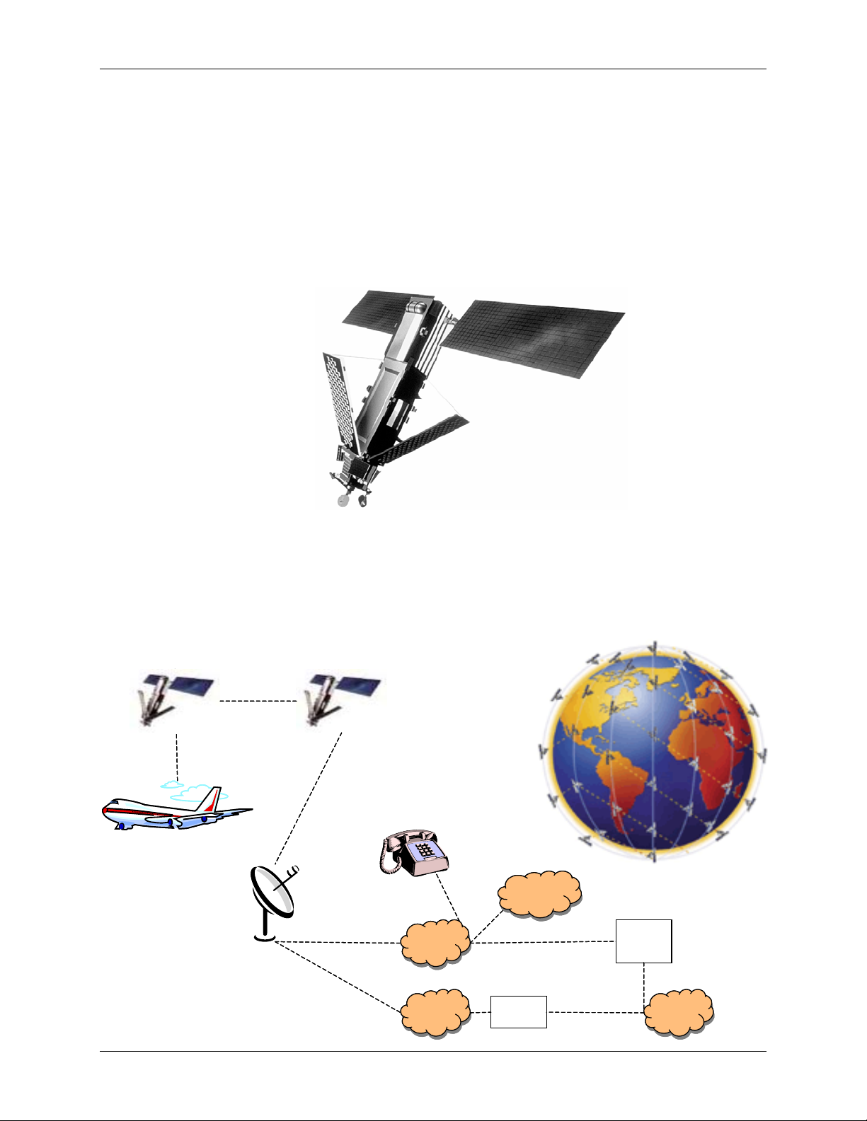
Iridium Satellite Network
The Iridium Satellite System is the only current provider of truly global, truly mobile
satellite voice and data solutions with complete coverage of the Earth (including
oceans, airways and Polar regions). Through a constellation of 66 low-earth orbiting
(LEO) satellites operated by Boeing, Iridium delivers essential communications
services to and from remote areas where terrestrial communications are not
available. The service is ideally suited for the aviation industry as well as industrial
applications such as heavy construction, defense/military, emergency services,
maritime, mining, forestry, oil and gas.
Satellites................................66 (plus 6 in-orbit backup satellites)
Orbital Planes........................6
Orbit Altitude..........................485 miles (780 kilometers)
Inclination of Orbital Plane ....86.4 degrees
Orbital Period ........................100 minutes, 28 seconds
Satellite Weight .....................1,500 pounds (689 kilograms)
Spot Beams...........................48 per satellite (30 miles in diameter per beam)
PSTN
PSTN
Internet
Internet Internet
Internet
Corporate
Network
Corporate
Network
Internet
Service
Provider
BSN
ComHub
Iridium
Gateway
Packet Data
Circuit Voice/Data
Voice
Data
Data
PSTN
PSTN
Internet
Internet Internet
Internet
Corporate
Network
Corporate
Network
Internet
Service
Provider
BSN
ComHub
Iridium
Gateway
Packet Data
Circuit Voice/Data
Voice
Data
Data

Blue Sky Network August 2007
Page 6D1000(A) IRIDIUM SATCOM DATA SOLUTION 100177
GPS Satellite Navigation System
The Global Positioning System (GPS) is a worldwide radio-navigation system
formed from a constellation of satellites and their ground stations.
GPS uses these "man-made stars" as reference points to calculate positions
accurate to a matter of meters (like giving every square meter on the planet a unique
address).
GPS satellite signals are processed in a GPS receiver, enabling the receiver to
compute position, velocity and time. GPS receivers have been miniaturized to just a
few integrated circuits, and are becoming very economical, which makes the
technology accessible to virtually everyone.
While there are thousands of civil users of GPS world-wide, the system was
designed for the U. S. military. GPS is funded and operated by the U. S. Department
of Defense (DOD).
August 2007 Blue Sky Network
100177 D1000(A) IRIDIUM SATCOM DATA SOLUTION Page 7
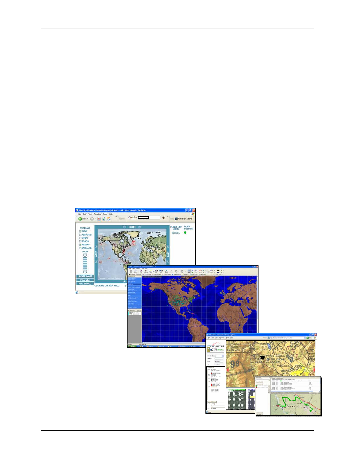
Flight Tracking
Blue Sky Network D1000(A) has already been integrated with several flight tracking
solutions, including Flight Explorer, the world's leading provider of Internet-based
real-time flight tracking.
Through a partnership with Flight Explorer, customers who purchase the Blue Sky
Network D1000(A) communication equipment and service will, as part of the
agreement, be provided with SkyRouter.com web-based aircraft tracking and
dynamic mapping capability powered by Flight Explorer (see below).
For more comprehensive flight tracking capabilities of both their Blue Sky Network-
tracked aircraft, as well as all other IFR air traffic in the US, Canada, the UK and
New Zealand, customers can use Flight Explorer Professional. Flight Explorer
Professional's comprehensive tracking and management capabilities include the
ability to generate numerous alerts and log files of specific events, interface with
other applications, determine the last known location of an aircraft, display graphical
and textual TFRs and more
Blue Sky Network has also integrated tracking data with the US Forest Service, and
Provante Technologies, Inc.

Blue Sky Network August 2007
Page 8D1000(A) IRIDIUM SATCOM DATA SOLUTION 100177
FAA/JAA APPROVAL
General
Acceptance for the installation and use of the D1000(A) must be sought through the
appropriate offices of the Federal Aviation Administration (FAA), Joint Aviation
Authorities (JAA) or other certifying agency.
The D1000 Satellite System is approved by the FAA (Federal Aviation
Administration) as compliant with the airworthiness requirements as defined in 14
CFR (Code of Federal Regulations), Part 23.
STC Number: ST01588LA – Cessna 414A Series as amended January 23, 2004
PMA #: PQ2389M
Supplement No.: 2
The Blue Sky Network Iridium-tuned Single-channel Antenna and the Iridium-tuned
Dual-channel Antenna have been approved by the FAA (Federal Aviation
Administration) as compliant with the airworthiness requirements as defined in 14
CFR (Code of Federal Regulations), Part 23.
Installation and Operational Approval Procedures
A functional ground test procedure and an operational flight check procedure (more
information on page 21) should be used to verify proper installation, functional
performance and electromagnetic compatibility with existing aircraft systems.
Instructions for Continued Airworthiness
The D1000(A) components require no routine servicing or maintenance. The
installation has no additional overhaul time limitations.

August 2007 Blue Sky Network
100177 D1000(A) IRIDIUM SATCOM DATA SOLUTION Page 9
Environmental Qualification
D1000 Modem Unit
The D1000 Modem Unit has been tested to DO-160D Section 21, Category M.
D1000 Control Unit
The D1000 Control Unit has been tested to DO-160D Section 21, Category M.
Single-Channel Antenna
The Single-Channel Antenna is qualified to DO-160, MIL-C-5541, MIL-E-5400, MIL-
STD-810 and TSO-C129.
Dual-Channel Antenna
The Dual-Channel Antenna is qualified to DO-160C, MIL-C-5541, MIL-E-5400, MIL-
STD-810 and TSO-C129a.

Blue Sky Network August 2007
Page 10 D1000(A) IRIDIUM SATCOM DATA SOLUTION 100177
EQUIPMENT SPECIFICATIONS AND DRAWINGS
BLUE SKY NETWORK D1000(A) Specifications
Height Maximum 3.5 inches (8.9 cm)
Width Maximum 5.3 inches (13.5 cm)
Depth Maximum 12.5 inches (31.8 cm)
Weight 6.1 pounds
Power Requirements 10VDC - 33VDC
Alternate Power Rechargeable Emergency Battery Backup
Nominal Current < 1A Continuous, < 3A Peak (at 28VDC)
Operating Temperature Range -20 degrees C to + 60 degrees C
Altitude Up to 50,000 feet
Iridium Data Circuit Frequency L-Band
Short Burst Data Frequency L-Band
GPS Frequency L-Band
LED Indicators Power (ON/OFF)
Iridium and GPS Signal Strength
Message Waiting (ON/OFF)
Ethernet (LINK/ACTIVE)
Quick Position (ON/OFF)
Laptop/PDA I/O Ethernet (RJ-45)
Sensor Data I/O 2 RS-232 DB9 (only 1 port, if using D1000A)
Antenna Options Single or dual channel GPS/Iridium tuned
fully TSOed
FAA Certification DO-160D / STC

August 2007 Blue Sky Network
100177 D1000(A) IRIDIUM SATCOM DATA SOLUTION Page 11
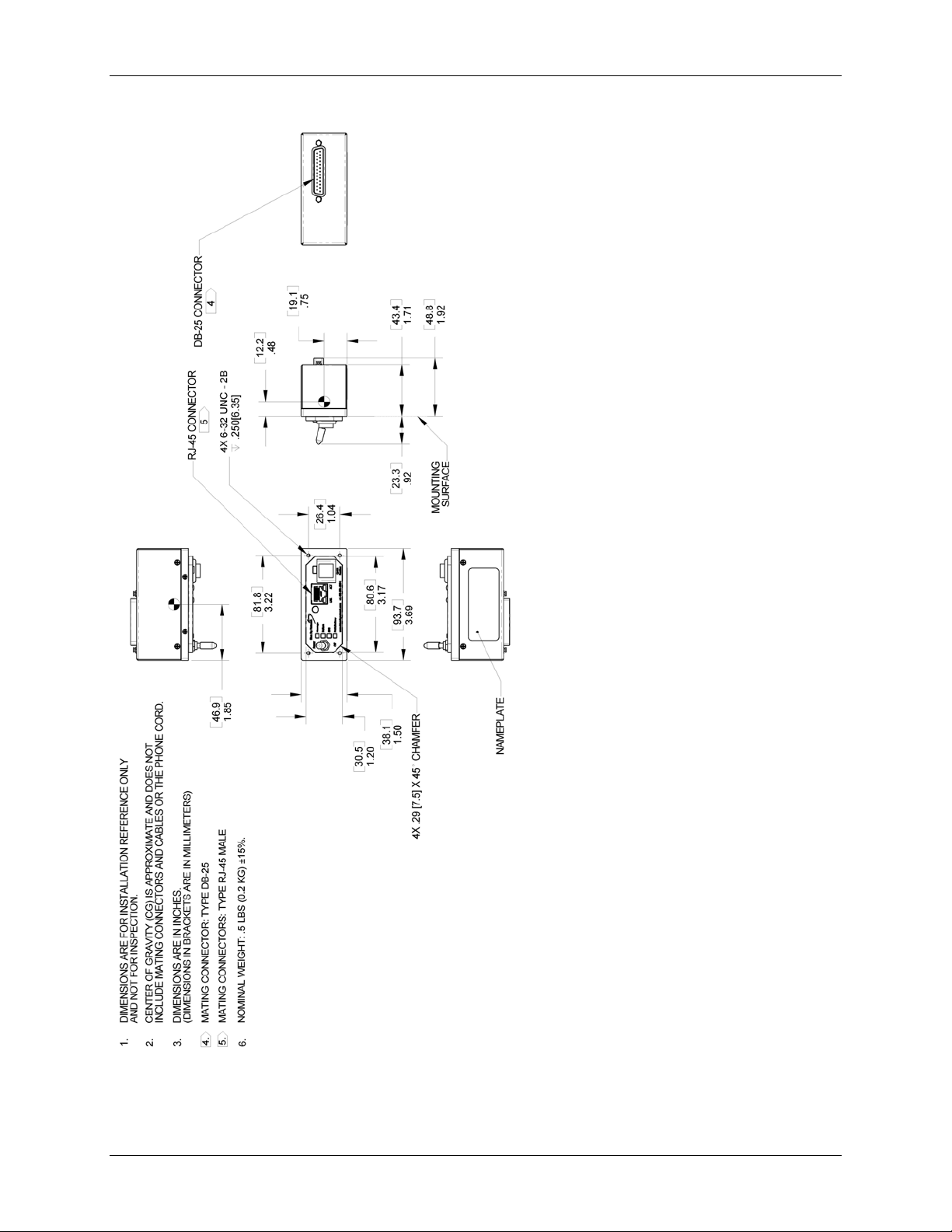
D-1000 (A) Modem Mechanical Specifications – 100140 (A)
OBS: Please note that Serial 2 on the D1000 becomes Control Head on D1000As.
Blue Sky Network August 2007
Page 12 D1000(A) IRIDIUM SATCOM DATA SOLUTION 100177
D-1000 Control Unit Mechanical Specifications (100160)

August 2007 Blue Sky Network
100177 D1000(A) IRIDIUM SATCOM DATA SOLUTION Page 13
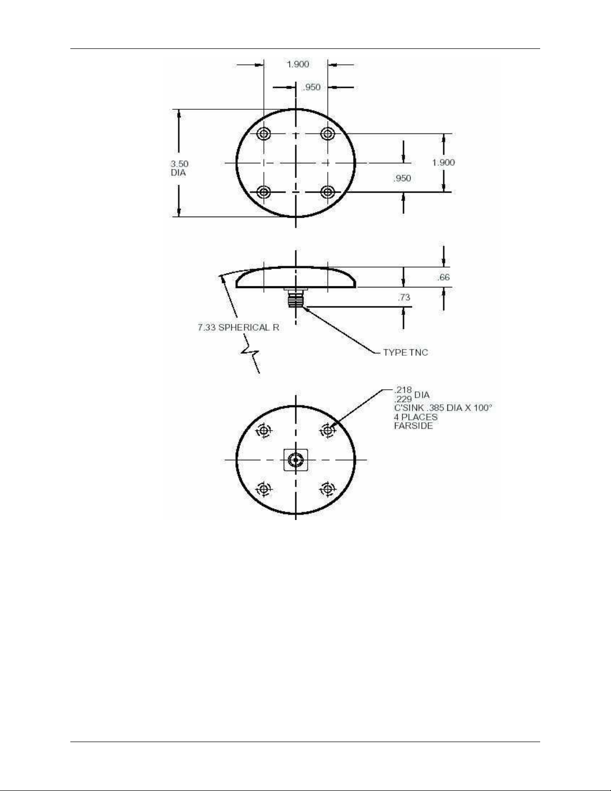
Single-Channel Antenna
The antenna is a spherical-radius molded radome that provides protection against
rain, ice, and lightning strikes. It is qualified for high-speed military and commercial
aircraft and is designed to DO-160, MIL-C-5541, MIL-E-5400, MIL-STD-810 and
TSO-C129 standards.
Frequency (Iridium/GPS)..................1616 -1626.5 MHz / 1575 ±10MHz
VSWR ............................................... 1.5:1
Polarization....................................... Right Hand Circular Polarization (RHCP)
Impedance........................................50 ohms
Power Handling ................................60 watts CW
Gain ..................................................+3 dBic @ Zenith
Lightning Protection.......................... DC grounded
Weight...............................................6 oz.
Material.............................................6061-T6 aluminum / thermoset plastic
Finish ................................................Skydrol resistant enamel
Blue Sky Network August 2007
Page 14 D1000(A) IRIDIUM SATCOM DATA SOLUTION 100177

August 2007 Blue Sky Network
100177 D1000(A) IRIDIUM SATCOM DATA SOLUTION Page 15
Dual-Channel Antenna
The Dual-Channel antenna is available for aircraft with multiple Iridium phone
installations. The antenna is a low profile dual-element molded radome that provides
coverage from 1610 to 1626.5 MHz for excellent Iridium operations and 1530-1660.5
MHz for low gain data application. It is designed to DO-160C, MIL-C-5541, MIL-E-
5400, MIL-STD-810 and TSO-C129a standards and is qualified for high-speed
military and commercial aircraft.
Frequency
J1 ..................................1610 - 1626.5 MHz
J2 ..................................1530 - 1660.5 MHz
VSWR .................................. 2.0:1
Polarization..........................Right Hand Circular Polarization (RHCP)
Impedance...........................50 ohms
Power Handling ...................60 watts
Gain .....................................+3 dBic @ Zenith
Lightning Protection.............DC grounded
Weight..................................16 oz.
Material................................6061-T6 aluminum / thermoset plastic
Finish ...................................Skydrol resistant enamel

Blue Sky Network August 2007
Page 16 D1000(A) IRIDIUM SATCOM DATA SOLUTION 100177
Other manuals for D1000 Series
1
This manual suits for next models
3
Table of contents
Other Blue Sky Network GPS manuals

Blue Sky Network
Blue Sky Network HawkEye 7200 Operating instructions

Blue Sky Network
Blue Sky Network HawkEye 7200 Quick start guide

Blue Sky Network
Blue Sky Network HawkEye 6200 User manual

Blue Sky Network
Blue Sky Network HE100A User manual

Blue Sky Network
Blue Sky Network HawkEye 7200A-BB2327 User manual

Blue Sky Network
Blue Sky Network HawkEye Plus User manual

Blue Sky Network
Blue Sky Network D411 User manual

Blue Sky Network
Blue Sky Network SKYLINK User manual

Blue Sky Network
Blue Sky Network HawkEye 7200A-BB2327 User manual

Blue Sky Network
Blue Sky Network HawkEye 6300 Mk1 User manual


