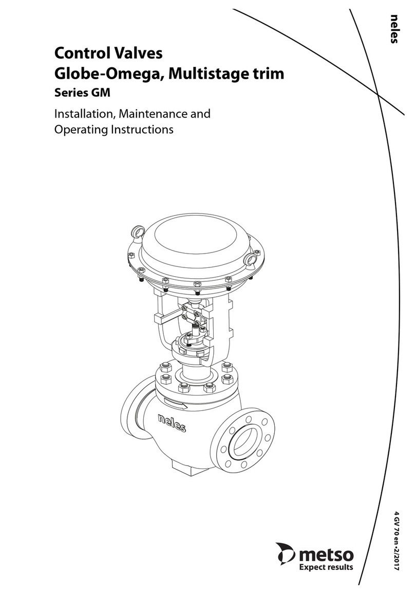
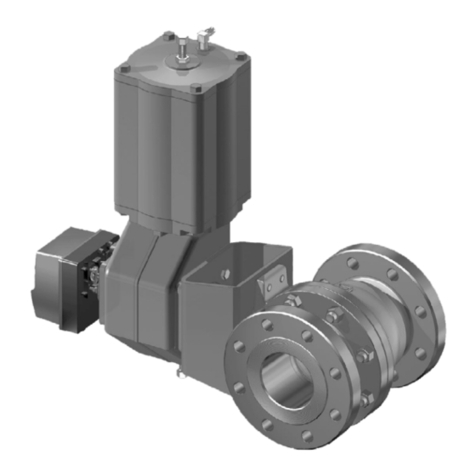
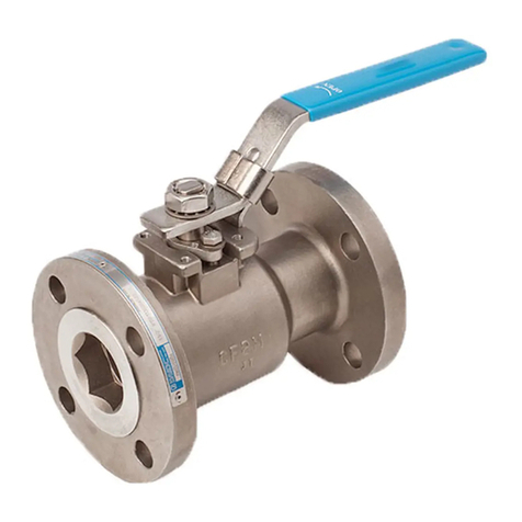
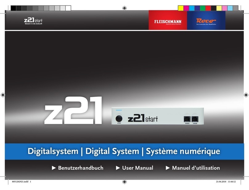
Metso NELDISC LW Series Operating and maintenance manual


This manual suits for next models
9
Table of contents
Other Metso Control Unit manuals

Metso
Metso L12 Series Operating and maintenance manual
Metso
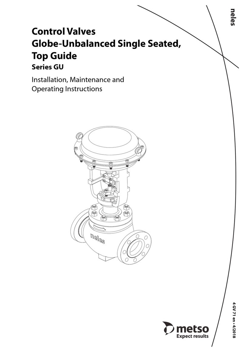
Metso GU series User manual

Metso
Metso Neles GB Series Operating and maintenance manual
Metso
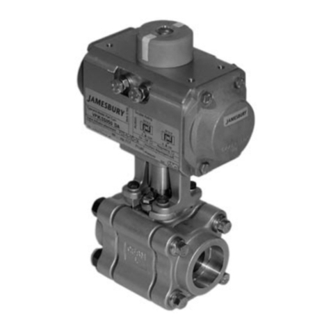
Metso Jamesbury 4000 B Operating and maintenance manual
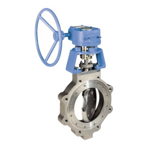
Metso
Metso Jamesbury Wafer-Sphere Series Operating and maintenance manual

Metso
Metso Finetrol Operating and maintenance manual
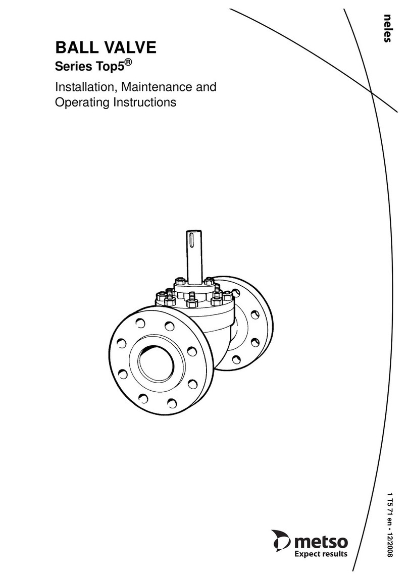
Metso
Metso Top 5 Series Operating and maintenance manual

Metso
Metso Ball Valves Operating and maintenance manual
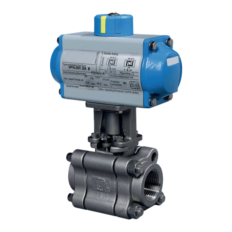
Metso
Metso Jamesbury 4000 Series User guide
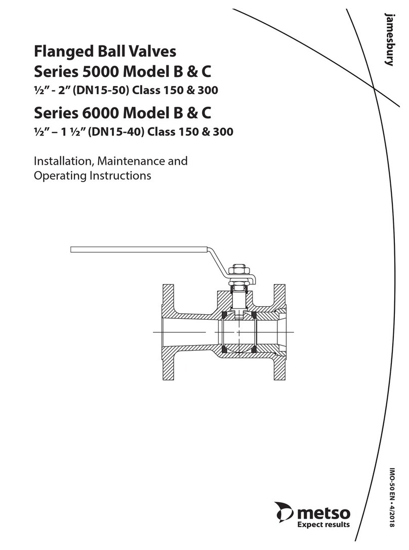
Metso
Metso Jamesbury 5000 series User manual

Metso
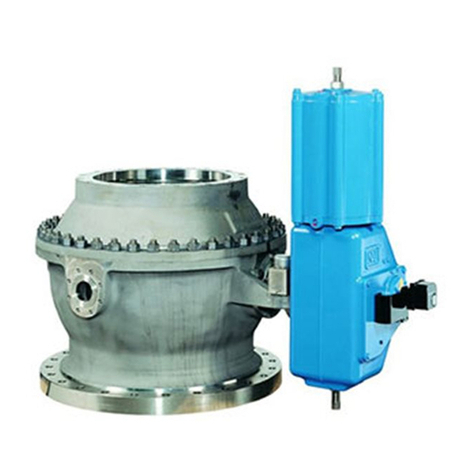
Metso Neles L4 Series Operating and maintenance manual
Metso
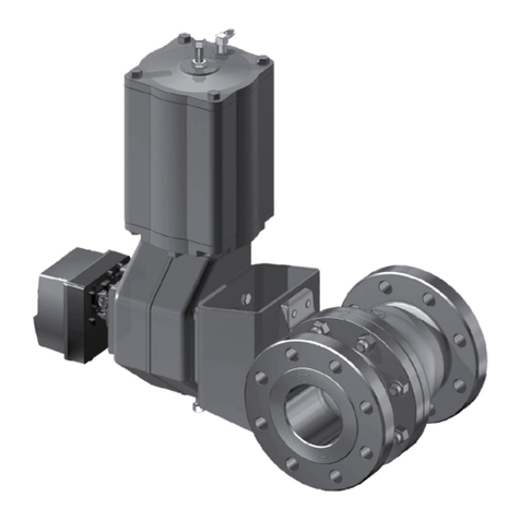
Metso PZ Series User manual
Metso
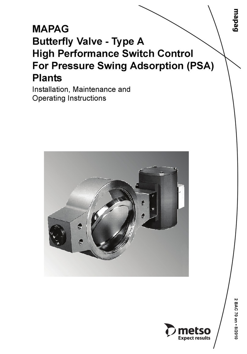
Metso MAPAG Butterfly valve Type A Operating and maintenance manual
Metso
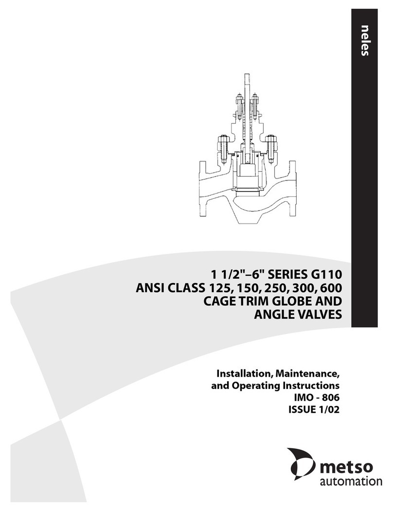
Metso ANSI CLASS 125 Operating and maintenance manual
Metso
Metso XT/XA Series Operating and maintenance manual
Metso
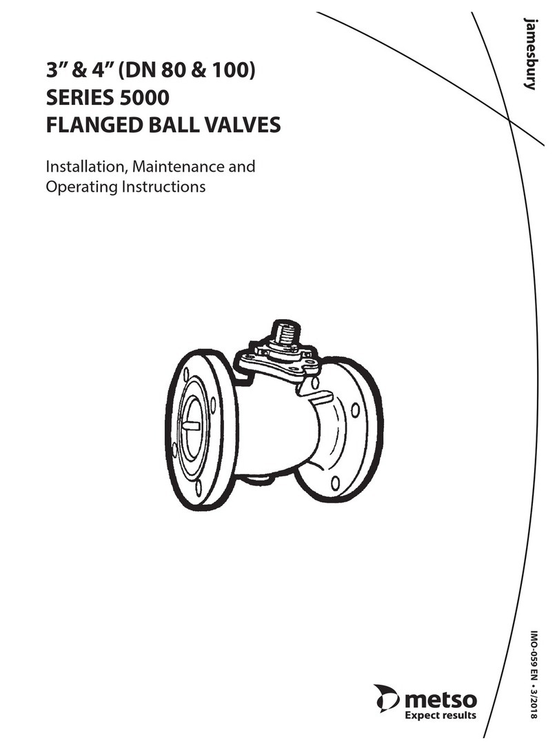
Metso Jamesbury 5000 series Operating and maintenance manual
Metso
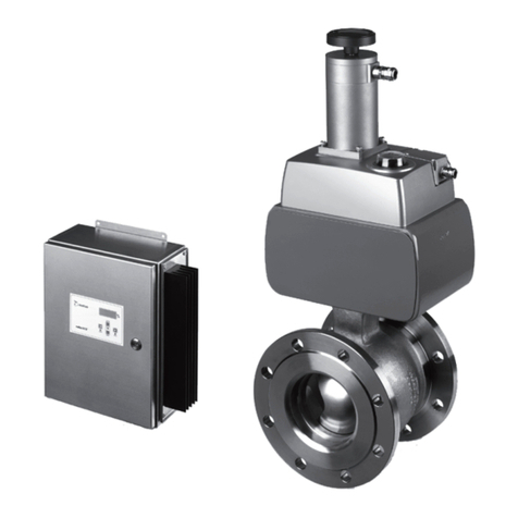
Metso NelesAce User manual
Metso
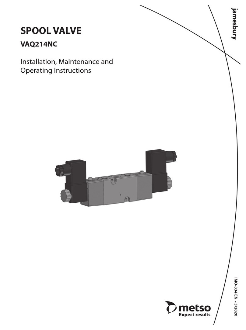
Metso Jamesbury VAQ214NC Series Operating and maintenance manual
Metso
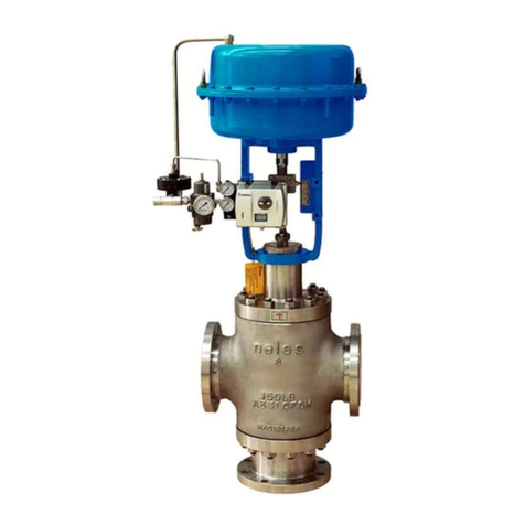
Metso GW Series Operating and maintenance manual
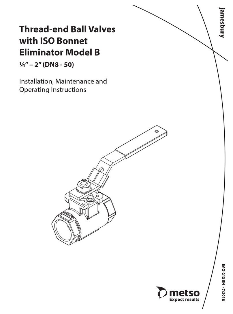
Metso
Metso jamesbury B Operating and maintenance manual
Popular Control Unit manuals by other brands

Pacific Recorders & Engineering Corporation
Pacific Recorders & Engineering Corporation LSM-10 Technical manual
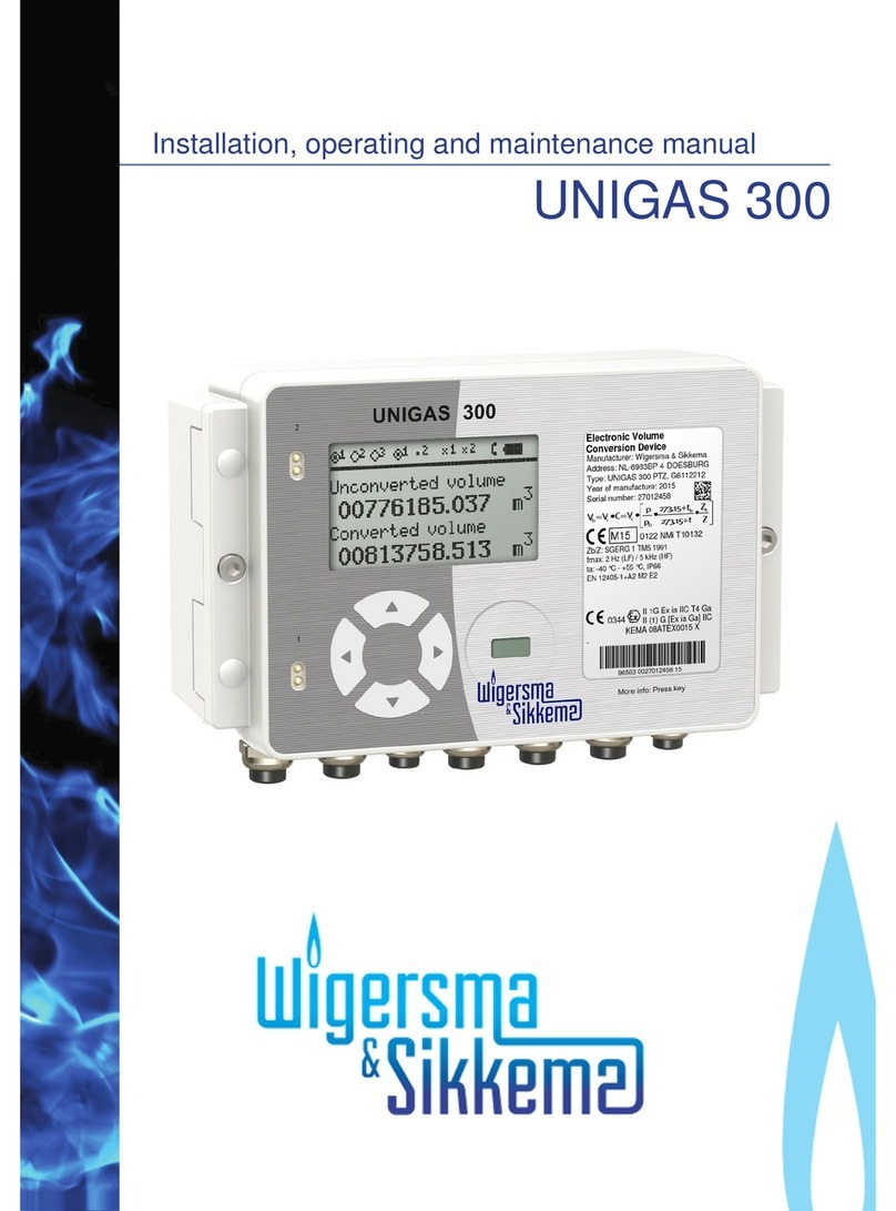
Wigersma & Sikkema
Wigersma & Sikkema UNIGAS 300 Installation, operating and maintenance manual
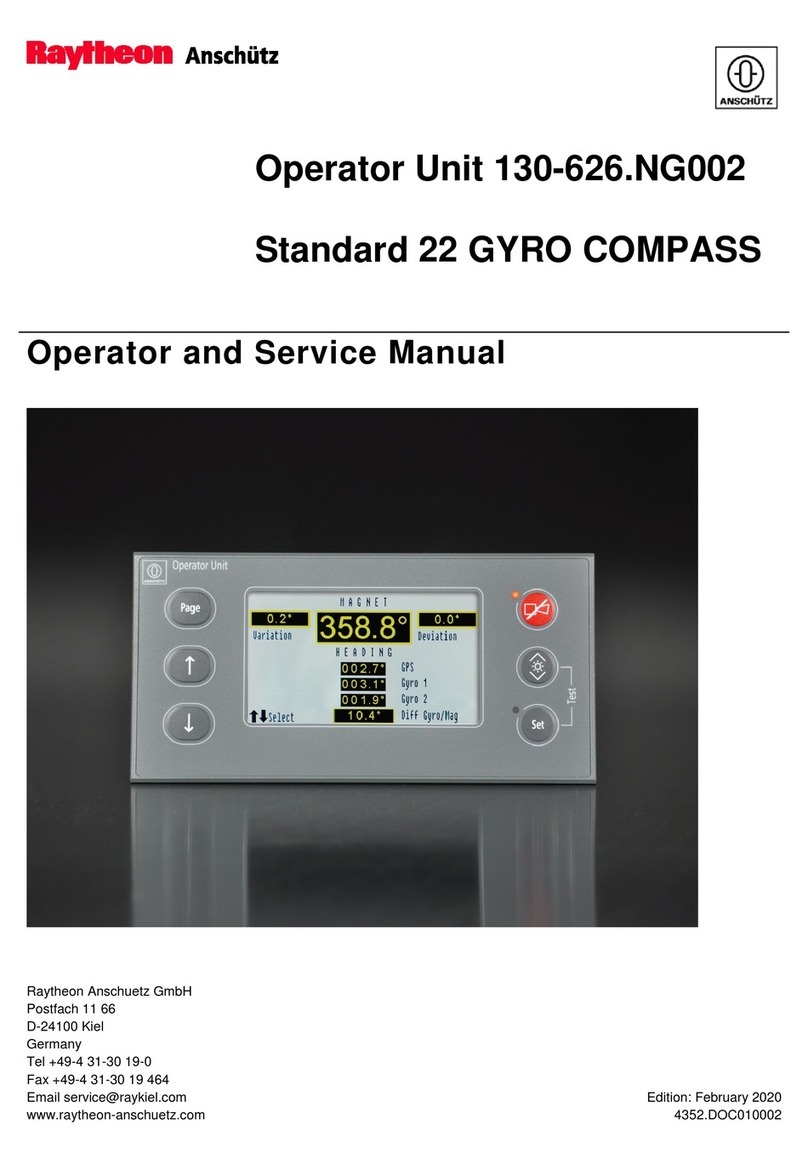
Raytheon Anschütz
Raytheon Anschütz Standard 22 GYRO COMPASS Operator's and service manual

Behringer
Behringer 2500 Series quick start guide

Stahl
Stahl 9469/35 Series operating instructions
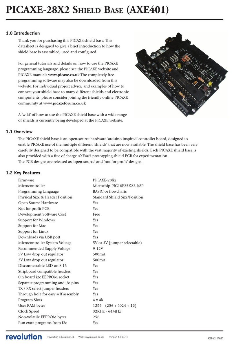
Picaxe
Picaxe AXE401 manual
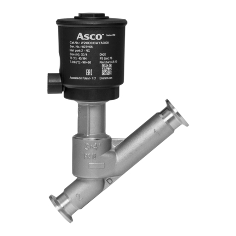
Asco
Asco 290 Series Installation and maintenance instructions

NiceRF
NiceRF RF24L01F20 manual
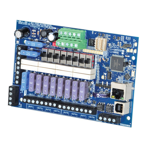
Altronix
Altronix LINQ8PD Installation and programming manual
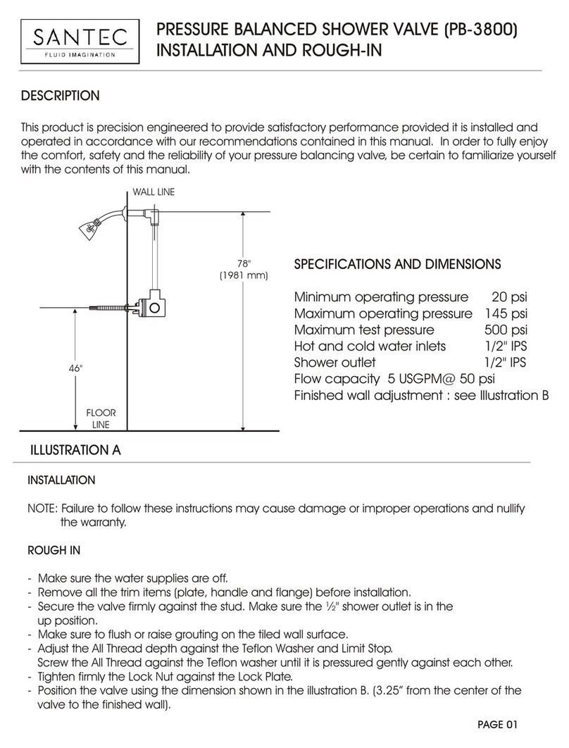
Santec
Santec Designer Series Installation and Rough-In
STIEBEL ELTRON
STIEBEL ELTRON FEB Operation and installation manual

Mitsubishi Electric
Mitsubishi Electric QJ71DN91 user manual
