Blue-White industries flexflo A-100N User manual

MODELA-100N
PERISTALTIC INJECTOR PUMP
OPERATING MANUAL
5300 Business Drive
Huntington Beach, CA 92649
USA
Phone: 714-893-8529 FAX:714-894-9492
INJECTOR
®
BLUE-WHITE
INDUSTRIES
L
A
I
T
U
Y
Q
P
T
R
C
O
U
D
R

TABLE OF CONTENTS
SECTION HEADING PAGE
1Introduction 2
2Specifications 3
3A-100N Features 3
4How to install the A-100N 4
4.1 Mounting location 4
4.2 Electrical connections 6
4.3 How to install the tubing and fittings 8
5How to operate the A-100N 10
5.1 How to adjust the output -Digital Timers 10
5.2 How to adjust the output -Fixed Timers 11
5.3 How to adjust the output -Variable Speed Control 11
6How to maintain the A-100N 12
6.1 Routine inspection and cleaning 12
6.2 How to clean and lubricate the A-100N 12
6.3 How to replace the pump tube 12
Replacement parts drawing 14
Replacement parts list 15
1.0 Introduction
Congratulations on purchasing the A-100N Peristaltic Metering Pump. TheA-100N is designed to inject
chemicals into piping systems. The pump has been tested by NSF International for use with 12 ½%
Sodium Hypochlorite. It is available from the factory with five optional feed rate adjustment mecha-
nisms.
1. Digitally Programmable Cycle Timer -The fixed speed pumping mechanism is turned on and off by
an electronic timer. The total-time cycle is adjustable from 1.0 second through 99 seconds. The on-time
cycle is adjustable from 0.5 seconds through 99 seconds. Settings from 0.5 through 9.9 seconds are
adjustable in 0.1 second increments.
2. Fixed Cycle Timer - The fixed speed pumping mechanism is turned on and off by an electronic timer.
The total cycle time is factory set. The available cycles are 1 minute, 10 minute, 5 second. The on-time
cycle is adjustable from 5% through 100% of the total cycle time. Alow feed “spa” model is available
with a 1 minute fixed total cycle with a 6 second maximum on time; ideal for spa and hot tub chlorina-
tion.
3. Variable Speed Controller - The speed of the pumping mechanism is adjustable from 5% through
100%.
4. Proportional Feed Input Signal - The fixed speed pumping mechanism is turned on and off by Blue-
®®
White’s DIGI-FLO Flowmeter (sold separately). Controls located on the DIGI-FLO are adjusted to
regulate the pump strokes per flow rate in the piping system.
5. Fixed Feed Rate - No adjustment control.
A-100N A-100N
2.0 Specifications
Maximum Working Pressure 100 psig / 6.9 bar*
o o
Maximum Fluid Temperature 130 F / 54 C
o o
Ambient Temperature Range 14 to 110 F / -10 to 43 C
Enclosure NEMA 3R (acceptable for outdoor use)
Duty Cycle Continuous
Maximum Solids 50% by volume
Maximum Viscosity 5,000 Centipoise
Maximum Suction Lift up to 30 ft. water
Power Requirements 115V60Hz 80 Watts
220V50Hz 40 Watts
230V60Hz 45 Watts
Dimensions 6-1/8” high x 10-1/8” wide x 9” deep
Weight 8 lb.
3.0 A-100N Features
!Peristaltic Pump Tube does not require valves.
!High outlet pressure capability of 100 psig.*
!High inlet suction lift capability of 30 feet.
!Quick-Disconnect inlet and outlet fittings available.
!Digital electronic feed rate control available.
!Pump Tube failure warning timer (digital models).
!200:1 adjustment turn down ratio (digital models).
!Acceptable for outdoor use.
!Corrosion proof Valox housing.
!Tamper resistant electronic control panel cover.
!Easy servicing.
!Includes suction tube strainer, tube weight, suction tubing, discharge tubing and injection fitting with
internal back-flow check valve and mounting hardware.
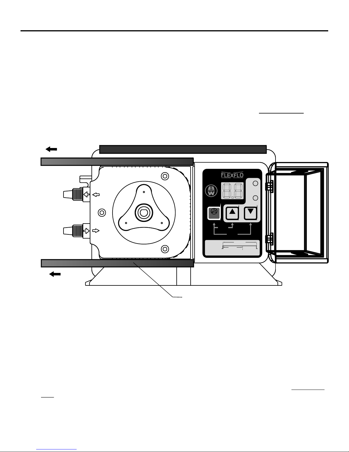
FIG. 3.0 PARTS LOCATOR DRAWING
* Most models.
** Slide both top & bottom clamps to the left only far enough to open the control cover.
L
A
I
T
U
Y
Q
P
T
R
C
O
U
D
RESET
TUBE LIFE WARNING TIMER
PRIME
99 SEC. CYCLE
UP DOWN
TOTAL
TIME
ON
TIME
ADJUST
CYCLE
WHEN LIT
STANDBY
RECOMMEND TUBE CHANGE WHEN DISPLAY BLINKS
CYCLE TIME
ADJUSTMENT
TOTALTIME
1 TO 99 SECONDS
ON TIME
.1 TO 99 SECONDS
98
3
Control
Control Cover
Pumphead Enclosure
Rear Plate
Pumphead
Cover
6.0
Pumptube
Assembly
Rotor
Assembly
98
1
Slide Clamps**
Page 2 Page 3

TABLE OF CONTENTS
SECTION HEADING PAGE
1Introduction 2
2Specifications 3
3A-100N Features 3
4How to install the A-100N 4
4.1 Mounting location 4
4.2 Electrical connections 6
4.3 How to install the tubing and fittings 8
5How to operate the A-100N 10
5.1 How to adjust the output -Digital Timers 10
5.2 How to adjust the output -Fixed Timers 11
5.3 How to adjust the output -Variable Speed Control 11
6How to maintain the A-100N 12
6.1 Routine inspection and cleaning 12
6.2 How to clean and lubricate the A-100N 12
6.3 How to replace the pump tube 12
Replacement parts drawing 14
Replacement parts list 15
1.0 Introduction
Congratulations on purchasing the A-100N Peristaltic Metering Pump. TheA-100N is designed to inject
chemicals into piping systems. The pump has been tested by NSF International for use with 12 ½%
Sodium Hypochlorite. It is available from the factory with five optional feed rate adjustment mecha-
nisms.
1. Digitally Programmable Cycle Timer -The fixed speed pumping mechanism is turned on and off by
an electronic timer. The total-time cycle is adjustable from 1.0 second through 99 seconds. The on-time
cycle is adjustable from 0.5 seconds through 99 seconds. Settings from 0.5 through 9.9 seconds are
adjustable in 0.1 second increments.
2. Fixed Cycle Timer - The fixed speed pumping mechanism is turned on and off by an electronic timer.
The total cycle time is factory set. The available cycles are 1 minute, 10 minute, 5 second. The on-time
cycle is adjustable from 5% through 100% of the total cycle time. Alow feed “spa” model is available
with a 1 minute fixed total cycle with a 6 second maximum on time; ideal for spa and hot tub chlorina-
tion.
3. Variable Speed Controller - The speed of the pumping mechanism is adjustable from 5% through
100%.
4. Proportional Feed Input Signal - The fixed speed pumping mechanism is turned on and off by Blue-
®®
White’s DIGI-FLO Flowmeter (sold separately). Controls located on the DIGI-FLO are adjusted to
regulate the pump strokes per flow rate in the piping system.
5. Fixed Feed Rate - No adjustment control.
A-100N A-100N
2.0 Specifications
Maximum Working Pressure 100 psig / 6.9 bar*
o o
Maximum Fluid Temperature 130 F / 54 C
o o
Ambient Temperature Range 14 to 110 F / -10 to 43 C
Enclosure NEMA 3R (acceptable for outdoor use)
Duty Cycle Continuous
Maximum Solids 50% by volume
Maximum Viscosity 5,000 Centipoise
Maximum Suction Lift up to 30 ft. water
Power Requirements 115V60Hz 80 Watts
220V50Hz 40 Watts
230V60Hz 45 Watts
Dimensions 6-1/8” high x 10-1/8” wide x 9” deep
Weight 8 lb.
3.0 A-100N Features
!Peristaltic Pump Tube does not require valves.
!High outlet pressure capability of 100 psig.*
!High inlet suction lift capability of 30 feet.
!Quick-Disconnect inlet and outlet fittings available.
!Digital electronic feed rate control available.
!Pump Tube failure warning timer (digital models).
!200:1 adjustment turn down ratio (digital models).
!Acceptable for outdoor use.
!Corrosion proof Valox housing.
!Tamper resistant electronic control panel cover.
!Easy servicing.
!Includes suction tube strainer, tube weight, suction tubing, discharge tubing and injection fitting with
internal back-flow check valve and mounting hardware.
FIG. 3.0 PARTS LOCATOR DRAWING
* Most models.
** Slide both top & bottom clamps to the left only far enough to open the control cover.
L
A
I
T
U
Y
Q
P
T
R
C
O
U
D
RESET
TUBE LIFE WARNING TIMER
PRIME
99 SEC. CYCLE
UP DOWN
TOTAL
TIME
ON
TIME
ADJUST
CYCLE
WHEN LIT
STANDBY
RECOMMEND TUBE CHANGE WHEN DISPLAY BLINKS
CYCLE TIME
ADJUSTMENT
TOTALTIME
1 TO 99 SECONDS
ON TIME
.1 TO 99 SECONDS
98
3
Control
Control Cover
Pumphead Enclosure
Rear Plate
Pumphead
Cover
6.0
Pumptube
Assembly
Rotor
Assembly
98
1
Slide Clamps**
Page 2 Page 3
4.0 How To Install the A-100N
Note: All diagrams are strictly for guideline purposes only. Always consult an expert before installing
the A-100N into specialized systems.
The A-100N should be serviced by qualified persons only.
4.1 Mounting Location
Choose an area located near the chemical supply tank, chemical injection point and electrical supply.
Although the pump is designed to withstand outdoor conditions, a cool, dry, well ventilated location is
recommended. Install the pump where it can be easily serviced.
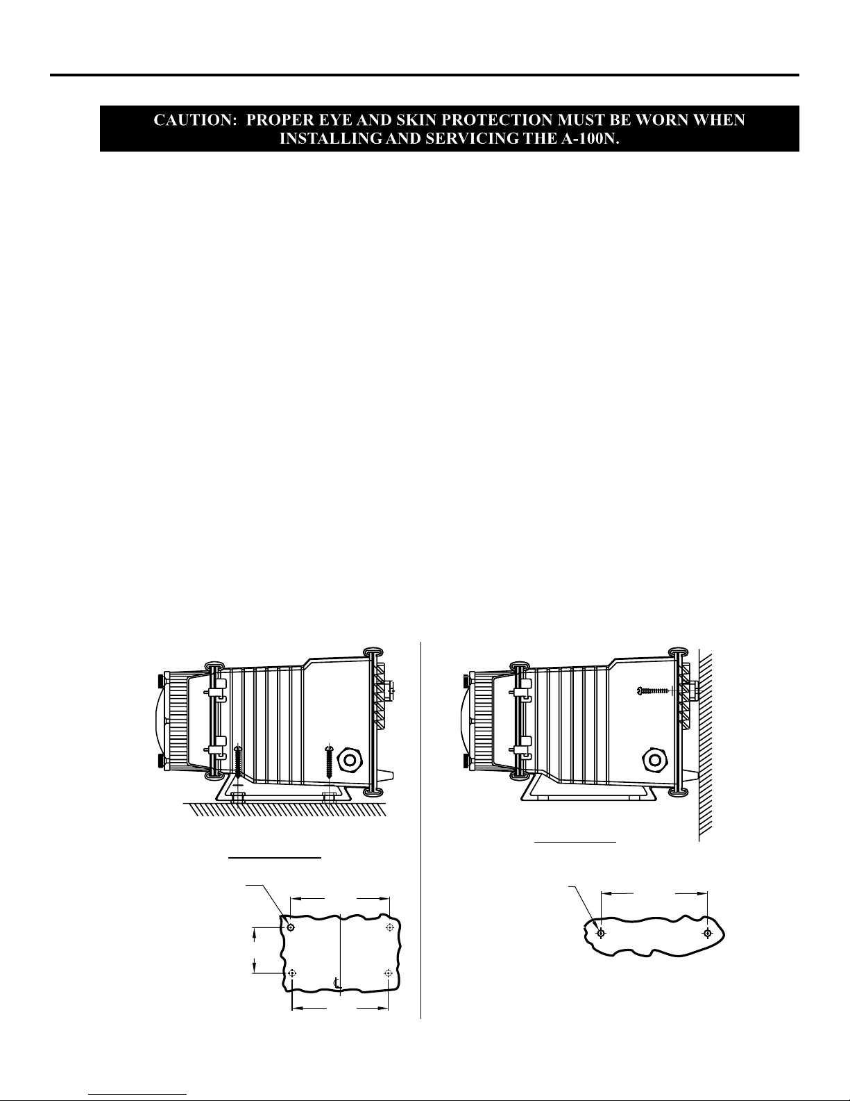
!Mount the pump to a secure surface or wall using the enclosed hardware. Wall mount to a solid surface
only. Mounting to drywall with anchors is not recommended.
!Keep the outlet (discharge) tubing as short as possible. Longer tubing increases the back pressure at the
pump tube.
!Do not mount the pump directly over your chemical container. Chemical fumes may damage the unit.
Mount the pump off to the side or at a lower level than the chemical container.
!Mounting the pump lower than the chemical container will gravity feed the chemical into the pump. This
“flooded suction” installation can reduce the time required to prime the pump. Install a shut-off valve,
pinch clamp or other means to halt the gravity feed to the pump during servicing.
!Your solution tank should be sturdy. Keep the tank covered to reduce fumes.
!Be sure your installation does not constitute a cross connection with the drinking water supply. Check
your local plumbing codes.
A-100N A-100N
FIG. 4.1 INJECTOR MOUNTING
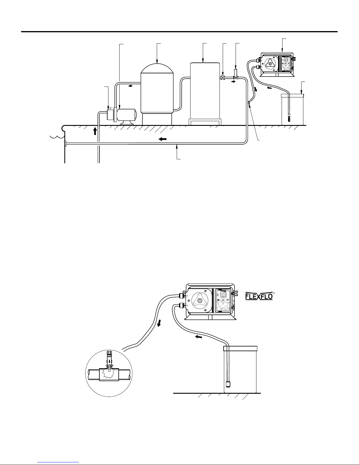
FIG. 4.2 SWIMMING POOLINSTALLATION
FIG. 4.3 TYPICAL INSTALLATION
11
Pool
223355
446677
88
99
1010
RECOMMENDTUBE CHANGE WHEN DISPLAY BLINKS
WHENLIT
ADJUST
TIME
TOTAL
TIME
ON
DOWN
ADJUSTMENT
CYCLETIME
.1TO99 SECONDS
TUBELIFE WARNING TIMER
ONTIME
1TO99 SECONDS
TOTALTIME
RESET
R
U
P
Q
99SEC. CYCLE
STANDBY
PRIME
UP
C
D
O
U
T
A
I
L
Y
T
CYCLE
1. Strainer 7. Injector ®
2. Circulation Pump Blue-White A-100N
3. Filter 8. Solution Tank
4. Heater 9. Injection Fitting
5. Check Valve 10. Return Line
6. Flowmeter ®
Blue-White F-300
Discharge
Tube
Pumping unit
R
Suction
Tube Chemical
Container
RECOMMENDTUBE CHANGE WHEN DISPLAY BLINKS
WHENLIT
ADJUST
TIME
TOTAL
TIME
ON
DOWN
ADJUSTMENT
CYCLETIME
.1TO 99 SECONDS
TUBELIFE WARNING TIMER
ONTIME
1TO 99 SECONDS
TOTALTIME
RESET
R
U
P
Q
99SEC. CYCLE
STANDBY
PRIME
UP
C
D
O
U
T
A
I
L
Y
T
CYCLE
¼" & ½" NPTInjector
Page 4 Page 5
Floor Mount
7-3/8”
7-5/8”
3-1/2”
8-3/16”
Drill .156 Dia. (5/32)
For Self-Tap Screw
#10 X 1” Phillips Steel
4 Places
Drill .156 Dia. (5/32)
For Self-Tap Screw
#10 X 1” Phillips Steel
2 Places
Note: For wall-mounting, recommend drill & thread into
solid wood only.
Wall Mount
4.0 How To Install the A-100N
Note: All diagrams are strictly for guideline purposes only. Always consult an expert before installing
the A-100N into specialized systems.
The A-100N should be serviced by qualified persons only.
4.1 Mounting Location
Choose an area located near the chemical supply tank, chemical injection point and electrical supply.
Although the pump is designed to withstand outdoor conditions, a cool, dry, well ventilated location is
recommended. Install the pump where it can be easily serviced.
!Mount the pump to a secure surface or wall using the enclosed hardware. Wall mount to a solid surface
only. Mounting to drywall with anchors is not recommended.
!Keep the outlet (discharge) tubing as short as possible. Longer tubing increases the back pressure at the
pump tube.
!Do not mount the pump directly over your chemical container. Chemical fumes may damage the unit.
Mount the pump off to the side or at a lower level than the chemical container.
!Mounting the pump lower than the chemical container will gravity feed the chemical into the pump. This
“flooded suction” installation can reduce the time required to prime the pump. Install a shut-off valve,
pinch clamp or other means to halt the gravity feed to the pump during servicing.
!Your solution tank should be sturdy. Keep the tank covered to reduce fumes.
!Be sure your installation does not constitute a cross connection with the drinking water supply. Check
your local plumbing codes.
A-100N A-100N
FIG. 4.1 INJECTOR MOUNTING
FIG. 4.2 SWIMMING POOLINSTALLATION
FIG. 4.3 TYPICAL INSTALLATION
11
Pool
223355
446677
88
99
1010
RECOMMENDTUBE CHANGE WHEN DISPLAY BLINKS
WHENLIT
ADJUST
TIME
TOTAL
TIME
ON
DOWN
ADJUSTMENT
CYCLETIME
.1TO99 SECONDS
TUBELIFE WARNING TIMER
ONTIME
1TO99 SECONDS
TOTALTIME
RESET
R
U
P
Q
99SEC. CYCLE
STANDBY
PRIME
UP
C
D
O
U
T
A
I
L
Y
T
CYCLE
1. Strainer 7. Injector ®
2. Circulation Pump Blue-White A-100N
3. Filter 8. Solution Tank
4. Heater 9. Injection Fitting
5. Check Valve 10. Return Line
6. Flowmeter ®
Blue-White F-300
Discharge
Tube
Pumping unit
R
Suction
Tube Chemical
Container
RECOMMENDTUBE CHANGE WHEN DISPLAY BLINKS
WHENLIT
ADJUST
TIME
TOTAL
TIME
ON
DOWN
ADJUSTMENT
CYCLETIME
.1TO 99 SECONDS
TUBELIFE WARNING TIMER
ONTIME
1TO 99 SECONDS
TOTALTIME
RESET
R
U
P
Q
99SEC. CYCLE
STANDBY
PRIME
UP
C
D
O
U
T
A
I
L
Y
T
CYCLE
¼" & ½" NPTInjector
Page 4 Page 5
Floor Mount
7-3/8”
7-5/8”
3-1/2”
8-3/16”
Drill .156 Dia. (5/32)
For Self-Tap Screw
#10 X 1” Phillips Steel
4 Places
Drill .156 Dia. (5/32)
For Self-Tap Screw
#10 X 1” Phillips Steel
2 Places
Note: For wall-mounting, recommend drill & thread into
solid wood only.
Wall Mount
A-100N A-100N
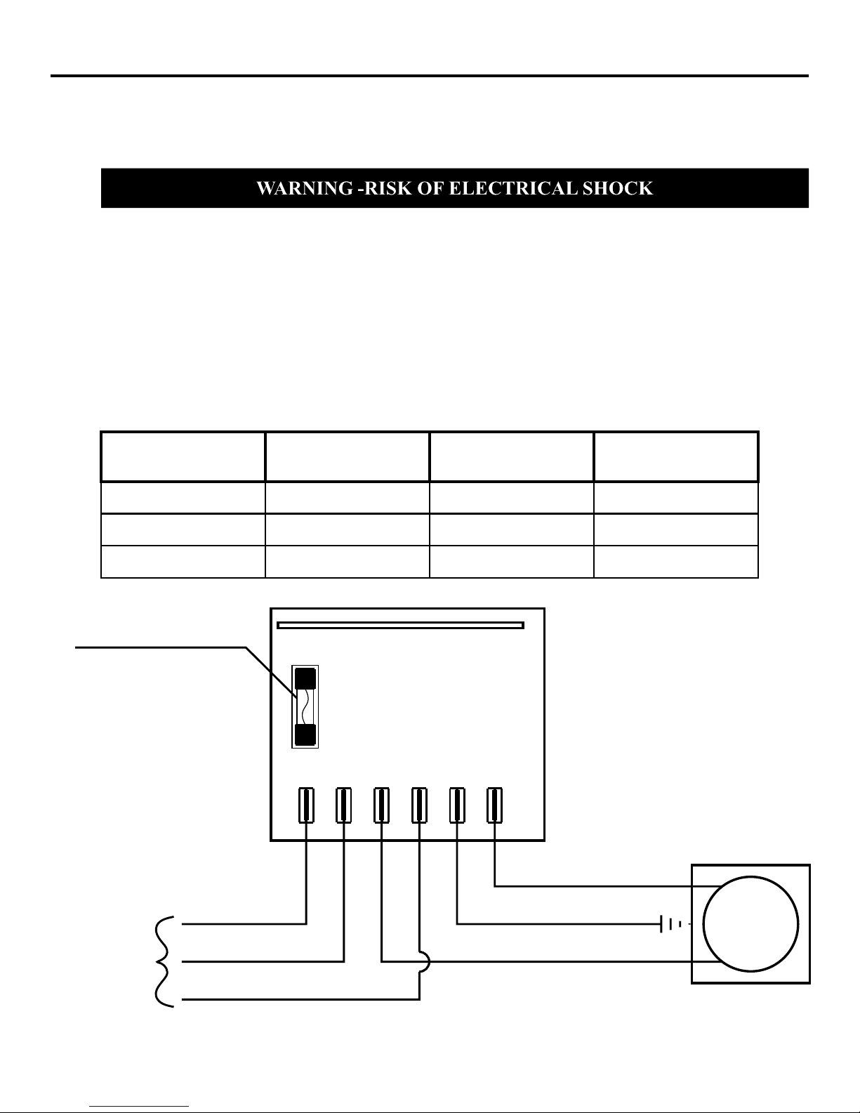
4.2 Electrical Connections
Be certain to connect the pump to the proper supply voltage. Using the incorrect voltage will damage
the pump and may result in injury. The voltage requirement is printed on the pump serial label.
Note: When in doubt regarding your electrical installation, contact a licensed electrician.
The A-100N is supplied with either a ground wire conductor and a grounding type attachment plug
(power cord) or a junction box for field wiring.
POWER CORD MODELS -To reduce the risk of electric shock, be certain that the power cord is
connected only to a properly grounded, grounding type receptacle.
JUNCTION BOX MODELS -To reduce the risk of electric shock, be certain that a grounding conduc-
tor is connected to the green grounding conductor located in the junction box.
INPUT
VOLTAGE
115V 60Hz
220V 50Hz
230V 60Hz
HOT
LEADWIRE
YELLOW
YELLOW
YELLOW
NEUTRAL
LEADWIRE
BLUE
BROWN
RED
GROUND
LEADWIRE
GREEN
GREEN
GREEN
FIG. 4.5 WIRING DIAGRAM - DIGITAL TIMER
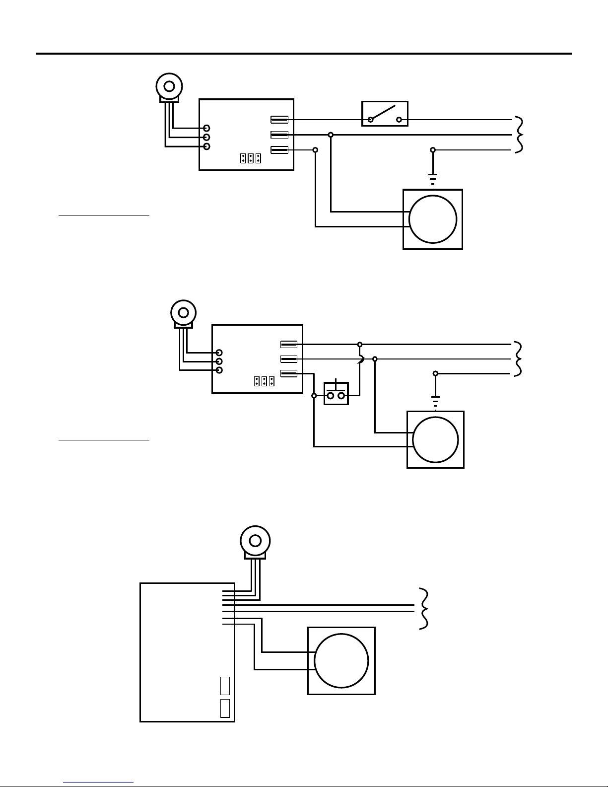
FIG. 4.6 WIRING DIAGRAM - FIXEDTIMERS
FIG. 4.7 WIRING DIAGRAM - LOWFEED “SPA” PERCENTAGE TIMER
FIG. 4.8 WIRING DIAGRAM -VARIABLE SPEED CONTROLLER
T3
Neutral-l2
Hot-l1 Earth
Ground Output
T2 T1 T4 T5 T6
Motor
Hot (yellow)
Neutral (blue/brown/red)
Common
Hot
Ground
AC
Input
Power
Circuit
Board
2A
250VAC
Protector Fuse
2 Amps, 250 Volt AC
(little Fuse #235002 or Equiv.)
Ground (green)
(factory Setting)
(factory Setting)
Power
Switch
Cycle Adjustment
Potentiometer
T3
T2
T1 AC
Input
Power
Hot
Common
Ground (green)
Timer
Board
Hot
Neutral
AC/LOAD
AC
LOAD
JB2 JB3
JB1
AC
Motor
Page 6 Page 7
Cycle Adjustment
Potentiometer
AC
Input
Power
Hot
Common
Ground (green)
Timer
Board
Hot
Neutral
AC/LOAD
AC
LOAD
JB2 JB3
JB1
AC
Motor
Momentary
By-pass
Switch
T3
T2
T1
Jb1, Jb2, Jb3 = Voltage Selector Jumpers
Jumpers Configuration
Install Jb1 & Jb3, (Jb2 left open) = 115 VAC input
Remove all jumpers (Jb1, Jb2, & Jb3 left open) = 230 V AC input
Jb1, Jb2, Jb3 = Voltage Selector Jumpers
Jumpers Configuration
Install Jb1 & Jb3, (Jb2 left open) = 115 VAC input
Remove all jumpers (Jb1, Jb2, & Jb3 left open) = 230 V AC input
Speed Adjustment
Potentiometer
120 VAC
Input
Power
Hot (yellow)
Common (white)
Red (+)
Min
Max
Black (-)
Controller
Board
DC
Motor
50K50K
A-100N A-100N
4.2 Electrical Connections
Be certain to connect the pump to the proper supply voltage. Using the incorrect voltage will damage
the pump and may result in injury. The voltage requirement is printed on the pump serial label.
Note: When in doubt regarding your electrical installation, contact a licensed electrician.
The A-100N is supplied with either a ground wire conductor and a grounding type attachment plug
(power cord) or a junction box for field wiring.
POWER CORD MODELS -To reduce the risk of electric shock, be certain that the power cord is
connected only to a properly grounded, grounding type receptacle.
JUNCTION BOX MODELS -To reduce the risk of electric shock, be certain that a grounding conduc-
tor is connected to the green grounding conductor located in the junction box.
INPUT
VOLTAGE
115V 60Hz
220V 50Hz
230V 60Hz
HOT
LEADWIRE
YELLOW
YELLOW
YELLOW
NEUTRAL
LEADWIRE
BLUE
BROWN
RED
GROUND
LEADWIRE
GREEN
GREEN
GREEN
FIG. 4.5 WIRING DIAGRAM - DIGITAL TIMER
FIG. 4.6 WIRING DIAGRAM - FIXEDTIMERS
FIG. 4.7 WIRING DIAGRAM - LOWFEED “SPA” PERCENTAGE TIMER
FIG. 4.8 WIRING DIAGRAM -VARIABLE SPEED CONTROLLER
T3
Neutral-l2
Hot-l1 Earth
Ground Output
T2 T1 T4 T5 T6
Motor
Hot (yellow)
Neutral (blue/brown/red)
Common
Hot
Ground
AC
Input
Power
Circuit
Board
2A
250VAC
Protector Fuse
2 Amps, 250 Volt AC
(little Fuse #235002 or Equiv.)
Ground (green)
(factory Setting)
(factory Setting)
Power
Switch
Cycle Adjustment
Potentiometer
T3
T2
T1 AC
Input
Power
Hot
Common
Ground (green)
Timer
Board
Hot
Neutral
AC/LOAD
AC
LOAD
JB2 JB3
JB1
AC
Motor
Page 6 Page 7
Cycle Adjustment
Potentiometer
AC
Input
Power
Hot
Common
Ground (green)
Timer
Board
Hot
Neutral
AC/LOAD
AC
LOAD
JB2 JB3
JB1
AC
Motor
Momentary
By-pass
Switch
T3
T2
T1
Jb1, Jb2, Jb3 = Voltage Selector Jumpers
Jumpers Configuration
Install Jb1 & Jb3, (Jb2 left open) = 115 VAC input
Remove all jumpers (Jb1, Jb2, & Jb3 left open) = 230 V AC input
Jb1, Jb2, Jb3 = Voltage Selector Jumpers
Jumpers Configuration
Install Jb1 & Jb3, (Jb2 left open) = 115 VAC input
Remove all jumpers (Jb1, Jb2, & Jb3 left open) = 230 V AC input
Speed Adjustment
Potentiometer
120 VAC
Input
Power
Hot (yellow)
Common (white)
Red (+)
Min
Max
Black (-)
Controller
Board
DC
Motor
50K50K

A-100N A-100N
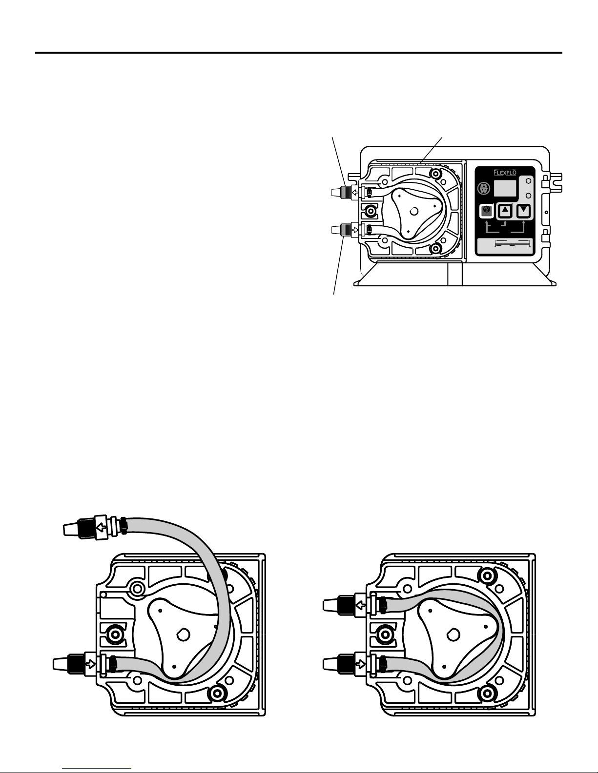
4.3 How To Install the Tubing and Fittings
4.3.1 Inlet Tubing - (Compression tube models) -Locate the inlet fitting of the Pump Tube, see fig 6.1.
Remove the tube nut. Push the clear PVC suction tubing onto the compression barb of the fitting. Use
the tube nut to secure the tube. Hand tighten only.
o
Inlet Tubing - (Quick-Connect models) - Locate the black, 90 elbow, low pressure Quick-Connect
inlet fitting, see fig 6.1. Connect the clear suction tubing to the hose barb. Check that the O-ring is in
place on the Pump Tube fitting and press the Quick-Connect fitting onto the Pump Tube. The fitting
should securely click in place.
4.3.2 Strainer -Trim the inlet end of the suction tubing so that the
strainer will rest approximately two inches from the bottom
of the solution tank. This will prevent sediment from clog-
ging the strainer. Slip the ceramic weight over the end of the
suction tube. Press the strainer into the end of the tube.
Secure the ceramic weight to the strainer. Drop the strainer
into the solution tank.
4.3.3 Outlet Tubing - (Compression tube models) - Locate the
outlet fitting of the Pump Tube, see fig 6.1. Remove the tube
nut. Push the opaque outlet (discharge) tubing onto the
compression barb of the fitting. Use the tube nut to secure
the tube. Hand tighten only.
Outlet Tubing - (Quick-Connect models) - Locate the
beige, high pressure Quick-Connect outlet fitting, see fig 6.1.
Remove the metal tube retaining nut from the Quick-Connect
fitting and slip it over the end of the opaque outlet (discharge) tubing. Connect the tubing to the hose
barb located on the fitting. Secure the tube to the fitting with the metal nut. Check that the O-ring is in
place on the outlet end of the Pump Tube and press the Quick-Connect fitting onto the Pump Tube. The
fitting should securely click into place.
Trim the other end of the outlet tube leaving only enough slack to connect it to the injection/check valve
fitting. Increasing the outlet tube length increases the pressure at the pump tube, particularly with
viscous fluids.
Keep the outlet tube as short as possible.
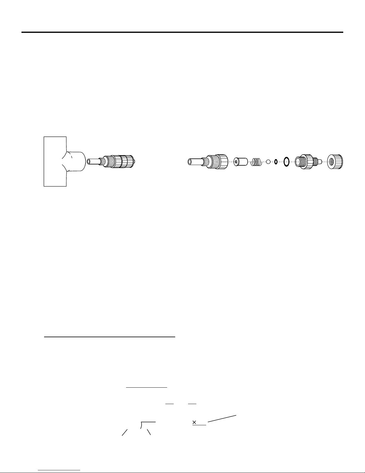
4.3.4 Injection/Check Valve Fitting Installation - The Injection/Check valve fitting is designed to install
directly into either 1/4” or 1/2” female pipe threads. This fitting will require periodic cleaning, espe-
cially when injecting fluids that calcify such as sodium hypochlorite. These lime deposits and other
build ups can clog the fitting increasing the back pressure and interfering with the check valve operation.
See section 6.0.
Install the Injection/Check valve directly into the piping system. Do not use a pipe stud with a tee for
insertion of the injection valve. The solution must inject directly into the flow stream.
Use Teflon thread sealing tape on the pipe threads. Push the opaque outlet (discharge) tubing onto the
compression barb of the Injection/Check valve fitting. Use the tube nut to secure the tube. Hand tighten
only.
Foot
Strainer
# 90002-200
Ceramic
Weight
# 90008-068
Tubing
Suction 3/8"
FIG. 4.9
FIG. 4.10 TEE INSTALLATION AND EXPLODEDVIEW
5.0 How to Operate the A-100N
5.1 How to Adjust The Output -DigitalTimers (fig. 5.1)
5.1.1 Digital Programmable Timer Model- The pumping mechanism is turned on and off by an electronic
cycle timer. The total-time cycle is adjustable from 1.0 seconds through 99 seconds.The on-time cycle
is adjustable from 0.5 seconds through 99 seconds. Example: If the total-time cycle is adjusted for 90
seconds and the on-time cycle is adjusted for 5 seconds, the pump will run for 5 seconds and turn off for
85 seconds (90 second total cycle). This cycle is repeated until either the standby button is pressed, the
cycle time is changed or the input power is disconnected from the pump.
AMOUNT OF CHEMICAL REQUIRED
PUMP MODEL’S MAXIMUM FLOW RATE (TotalTime Cycle) = ON-TIME CYCLE
EXAMPLE: Model A1N10D-6Q has a maximum flow rate of 1.42 oz. per minute.
How do I adjust the pump to inject .5 ounces of solution per minute?
.5 OUNCES
1.42 OUNCES (60 Seconds) = 21 Seconds
1.42 .352
.5
.352
60
21.12 = 21 seconds
OR
Max Flow Rate
of Your Pump Amount of
Chemical Desired
Total-Time Cycle
(See section 5.1.2)
Page 8 Page 9
A-100N A-100N
4.3 How To Install the Tubing and Fittings
4.3.1 Inlet Tubing - (Compression tube models) -Locate the inlet fitting of the Pump Tube, see fig 6.1.
Remove the tube nut. Push the clear PVC suction tubing onto the compression barb of the fitting. Use
the tube nut to secure the tube. Hand tighten only.
o
Inlet Tubing - (Quick-Connect models) - Locate the black, 90 elbow, low pressure Quick-Connect
inlet fitting, see fig 6.1. Connect the clear suction tubing to the hose barb. Check that the O-ring is in
place on the Pump Tube fitting and press the Quick-Connect fitting onto the Pump Tube. The fitting
should securely click in place.
4.3.2 Strainer -Trim the inlet end of the suction tubing so that the
strainer will rest approximately two inches from the bottom
of the solution tank. This will prevent sediment from clog-
ging the strainer. Slip the ceramic weight over the end of the
suction tube. Press the strainer into the end of the tube.
Secure the ceramic weight to the strainer. Drop the strainer
into the solution tank.
4.3.3 Outlet Tubing - (Compression tube models) - Locate the
outlet fitting of the Pump Tube, see fig 6.1. Remove the tube
nut. Push the opaque outlet (discharge) tubing onto the
compression barb of the fitting. Use the tube nut to secure
the tube. Hand tighten only.
Outlet Tubing - (Quick-Connect models) - Locate the
beige, high pressure Quick-Connect outlet fitting, see fig 6.1.
Remove the metal tube retaining nut from the Quick-Connect
fitting and slip it over the end of the opaque outlet (discharge) tubing. Connect the tubing to the hose
barb located on the fitting. Secure the tube to the fitting with the metal nut. Check that the O-ring is in
place on the outlet end of the Pump Tube and press the Quick-Connect fitting onto the Pump Tube. The
fitting should securely click into place.
Trim the other end of the outlet tube leaving only enough slack to connect it to the injection/check valve
fitting. Increasing the outlet tube length increases the pressure at the pump tube, particularly with
viscous fluids.
Keep the outlet tube as short as possible.
4.3.4 Injection/Check Valve Fitting Installation - The Injection/Check valve fitting is designed to install
directly into either 1/4” or 1/2” female pipe threads. This fitting will require periodic cleaning, espe-
cially when injecting fluids that calcify such as sodium hypochlorite. These lime deposits and other
build ups can clog the fitting increasing the back pressure and interfering with the check valve operation.
See section 6.0.
Install the Injection/Check valve directly into the piping system. Do not use a pipe stud with a tee for
insertion of the injection valve. The solution must inject directly into the flow stream.
Use Teflon thread sealing tape on the pipe threads. Push the opaque outlet (discharge) tubing onto the
compression barb of the Injection/Check valve fitting. Use the tube nut to secure the tube. Hand tighten
only.
Foot
Strainer
# 90002-200
Ceramic
Weight
# 90008-068
Tubing
Suction 3/8"
FIG. 4.9
FIG. 4.10 TEE INSTALLATION AND EXPLODEDVIEW
5.0 How to Operate the A-100N
5.1 How to Adjust The Output -DigitalTimers (fig. 5.1)
5.1.1 Digital Programmable Timer Model- The pumping mechanism is turned on and off by an electronic
cycle timer. The total-time cycle is adjustable from 1.0 seconds through 99 seconds.The on-time cycle
is adjustable from 0.5 seconds through 99 seconds. Example: If the total-time cycle is adjusted for 90
seconds and the on-time cycle is adjusted for 5 seconds, the pump will run for 5 seconds and turn off for
85 seconds (90 second total cycle). This cycle is repeated until either the standby button is pressed, the
cycle time is changed or the input power is disconnected from the pump.
AMOUNT OF CHEMICAL REQUIRED
PUMP MODEL’S MAXIMUM FLOW RATE (TotalTime Cycle) = ON-TIME CYCLE
EXAMPLE: Model A1N10D-6Q has a maximum flow rate of 1.42 oz. per minute.
How do I adjust the pump to inject .5 ounces of solution per minute?
.5 OUNCES
1.42 OUNCES (60 Seconds) = 21 Seconds
1.42 .352
.5
.352
60
21.12 = 21 seconds
OR
Max Flow Rate
of Your Pump Amount of
Chemical Desired
Total-Time Cycle
(See section 5.1.2)
Page 8 Page 9
A-100N A-100N
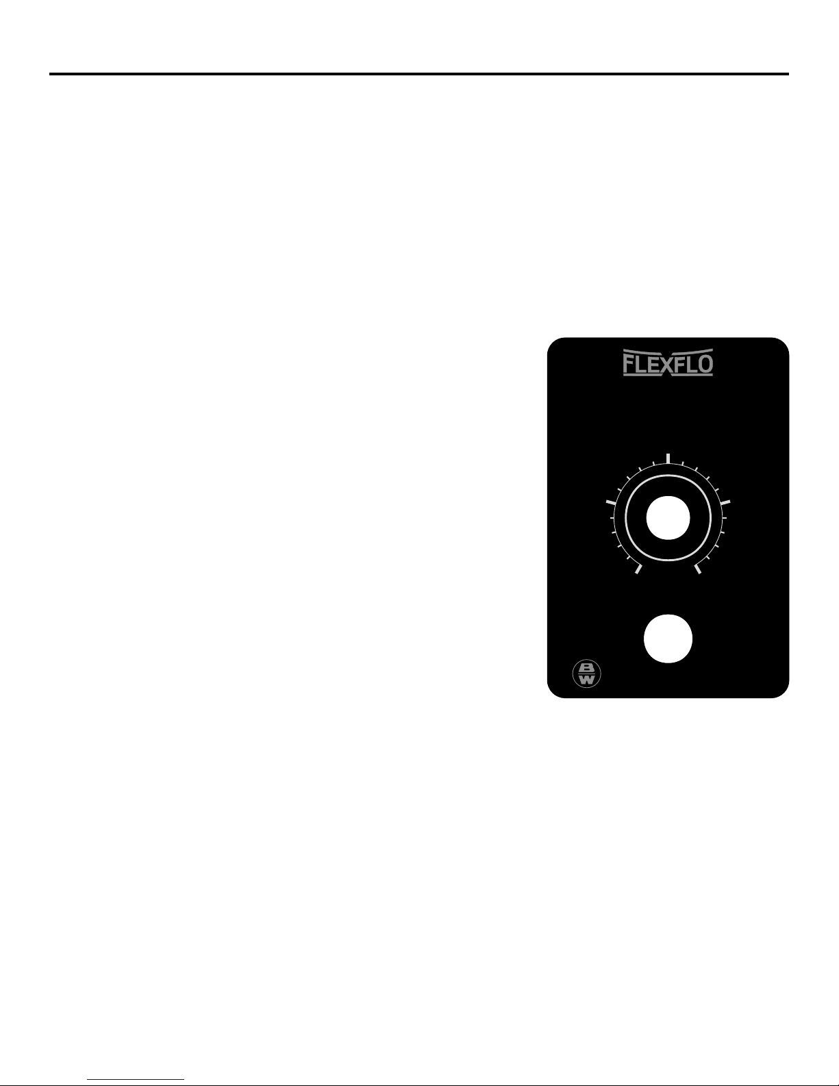
5.2 How to Adjust The Output -Fixed CycleTimers (fig. 5.2)
5.2.1 Fixed Cycle Timer Models -The pumping mechanism is turned on and off by an electronic cycle timer.
The total-time cycle is factory preset and is not user adjustable. The on-time cycle is adjustable from 5%
to 100% of the total cycle time (low feed “spa” timers adjust from .5 to 6 seconds with total time cycle
of 60 seconds). Example: If the total-time cycle is 60 seconds and the on-time cycle is adjusted for 25
percent, the pump will run for 15 seconds and turn off for 45 seconds (60 second total cycle). This cycle
is repeated until either the power switch is turned off, the cycle time is changed or the input power is
disconnected from the pump.
Note: When the input power is disconnected from theA-100N, the unit will maintain the last
adjusted settings. When power is restored to the pump, theA-100N will either automatically begin
to pump using the last time cycle setting, or maintain power-off status, depending on the power
switch status when the input power was disconnected.
A-100N
0% 100%
50%
75%
IO
25%
ON OFF
BLUE-WHITE INDUSTRIES
L
A
I
T
U
Y
Q
P
T
R
C
O
U
D
PERCENTAGE OF OUTPUT
5.1.3 Tube Life Warning Timer -The A-100N digital timer is equipped with a tube life warning timer. After
approximately 500 hours of accumulated running time (time-on), the display will continuously flash.
This is a reminder that the Pump Tube is nearing it’s minimum life expectancy and must be replaced.
Your actual tube life will depend on many factors such as the chemical used, back pressure, temperature
and motor RPM.
After replacing the pump tube, press the Standby button and the Down Arrow button at the same
time to reset the timer.
5.2.2 Fixed Cycle TimerAdjustment - Slide the slide clamps to the
left only far enough to open the control panel door.
!To adjust the On-Time, turn the adjustment knob.
!To Stop The Pump, switch off the power switch. Note: low feed
spa timers must be unplugged.
5.3 How to AdjustThe Output -Variable Speed Control
5.3.1 Variable Speed Models -The speed of the pumping mechanism
is adjustable from 5 % through 100%.
Note: When the input power is disconnected from theA-
100N, the unit will maintain the last adjusted settings. When
power is restored to the pump, theA-100N will either auto-
matically begin to pump using the last speed setting, or
maintain power-off status, depending on the power switch
status when the input power was disconnected.
5.3.2 Variable Speed ControllerAdjustment - Slide the slide clamps to the left only far enough to open the
control panel door.
!To adjust the Pump Speed, turn the adjustment knob.
!To Stop The Pump,switch off the power switch.
FIG. 5.2
L
A
I
T
U
Y
Q
P
T
R
C
O
U
D
RESET
TUBE LIFE WARNING TIMER
PRIME
99 SEC. CYCLE
UP DOWN
TOTAL
TIME
ON
TIME
ADJUST
CYCLE
WHEN LIT
STANDBY
RECOMMEND TUBE CHANGE WHEN DISPLAY BLINKS
CYCLE TIME
ADJUSTMENT
TOTAL TIME
1 TO 99 SECONDS
ON TIME
.1 TO 99 SECONDS
SLIDE CLAMP
Slide both top & bottom clamps to the left only far enough
(as shown) to open the control cover
5.1.2 Digital TimerAdjustment - Open the control panel door by sliding the upper and lower slide
clamps to the left. FIG. 5.1
!To Adjust the Total-Time Cycle, press the up or down arrow button while the Total-Time Cycle LED
indicator is lit.
!To Adjust the On-Time Cycle, press the up or down arrow button while the On-Time Cycle LED
indicator is lit.
!To override the timer forPriming The Pump, press the standby and up arrows at the same time. After
99 seconds, the timer will return to the original settings or press the standby button twice to exit.
!To Stop The Pump, press the standby button.
FIG. 5.1
Page 10 Page 11
A-100N A-100N
5.2 How to Adjust The Output -Fixed CycleTimers (fig. 5.2)
5.2.1 Fixed Cycle Timer Models -The pumping mechanism is turned on and off by an electronic cycle timer.
The total-time cycle is factory preset and is not user adjustable. The on-time cycle is adjustable from 5%
to 100% of the total cycle time (low feed “spa” timers adjust from .5 to 6 seconds with total time cycle
of 60 seconds). Example: If the total-time cycle is 60 seconds and the on-time cycle is adjusted for 25
percent, the pump will run for 15 seconds and turn off for 45 seconds (60 second total cycle). This cycle
is repeated until either the power switch is turned off, the cycle time is changed or the input power is
disconnected from the pump.
Note: When the input power is disconnected from theA-100N, the unit will maintain the last
adjusted settings. When power is restored to the pump, theA-100N will either automatically begin
to pump using the last time cycle setting, or maintain power-off status, depending on the power
switch status when the input power was disconnected.
A-100N
0% 100%
50%
75%
IO
25%
ON OFF
BLUE-WHITE INDUSTRIES
L
A
I
T
U
Y
Q
P
T
R
C
O
U
D
PERCENTAGE OF OUTPUT
5.1.3 Tube Life Warning Timer -The A-100N digital timer is equipped with a tube life warning timer. After
approximately 500 hours of accumulated running time (time-on), the display will continuously flash.
This is a reminder that the Pump Tube is nearing it’s minimum life expectancy and must be replaced.
Your actual tube life will depend on many factors such as the chemical used, back pressure, temperature
and motor RPM.
After replacing the pump tube, press the Standby button and the Down Arrow button at the same
time to reset the timer.
5.2.2 Fixed Cycle TimerAdjustment - Slide the slide clamps to the
left only far enough to open the control panel door.
!To adjust the On-Time, turn the adjustment knob.
!To Stop The Pump, switch off the power switch. Note: low feed
spa timers must be unplugged.
5.3 How to AdjustThe Output -Variable Speed Control
5.3.1 Variable Speed Models -The speed of the pumping mechanism
is adjustable from 5 % through 100%.
Note: When the input power is disconnected from theA-
100N, the unit will maintain the last adjusted settings. When
power is restored to the pump, theA-100N will either auto-
matically begin to pump using the last speed setting, or
maintain power-off status, depending on the power switch
status when the input power was disconnected.
5.3.2 Variable Speed ControllerAdjustment - Slide the slide clamps to the left only far enough to open the
control panel door.
!To adjust the Pump Speed, turn the adjustment knob.
!To Stop The Pump,switch off the power switch.
FIG. 5.2
L
A
I
T
U
Y
Q
P
T
R
C
O
U
D
RESET
TUBE LIFE WARNING TIMER
PRIME
99 SEC. CYCLE
UP DOWN
TOTAL
TIME
ON
TIME
ADJUST
CYCLE
WHEN LIT
STANDBY
RECOMMEND TUBE CHANGE WHEN DISPLAY BLINKS
CYCLE TIME
ADJUSTMENT
TOTAL TIME
1 TO 99 SECONDS
ON TIME
.1 TO 99 SECONDS
SLIDE CLAMP
Slide both top & bottom clamps to the left only far enough
(as shown) to open the control cover
5.1.2 Digital TimerAdjustment - Open the control panel door by sliding the upper and lower slide
clamps to the left. FIG. 5.1
!To Adjust the Total-Time Cycle, press the up or down arrow button while the Total-Time Cycle LED
indicator is lit.
!To Adjust the On-Time Cycle, press the up or down arrow button while the On-Time Cycle LED
indicator is lit.
!To override the timer forPriming The Pump, press the standby and up arrows at the same time. After
99 seconds, the timer will return to the original settings or press the standby button twice to exit.
!To Stop The Pump, press the standby button.
FIG. 5.1
Page 10 Page 11

A-100N A-100N
6.0 How to Maintain the A-100N
6.1 Routine Inspection and Maintenance
The A-100N requires very little maintenance. However, the pump and all accessories should be checked
weekly. This is especially important when pumping chemicals. Inspect all components for signs of
leaking, swelling, cracking, discoloration or corrosion. Replace worn or damaged components immedi-
ately.
Cracking, crazing, discoloration and the like during the first week of operation are signs of severe
chemical attack. If this occurs, immediately remove the chemical from the pump. Determine which
parts are being attacked and replace them with parts that have been manufactured using more suitable
materials. The manufacturer does not assume responsibility for damage to the pump that has been
caused by chemical attack.
6.2 How to Clean and Lubricate the A-100N
The A-100N will require occasional cleaning and lubricating. The amount will depend on the severity of
service.
]When changing the pump tube assembly, the pump head chamber, roller assembly and pump head cover
should be wiped free of any dirt and debris.
]The pump head cover bearing may require grease periodically. Apply a small amount of grease
(Aeroshell aviation grease #5 or equivalent) when necessary.
]Do not apply lubrication of any kind to the roller assembly or tube assembly.
]Periodically clean the injection/check valve assembly, especially when injecting fluids that calcify such
as sodium hypochlorite. These lime deposits and other build ups can clog the fitting, increase the back
pressure and interfere with the check valve operation. See section 4.3.4. Fig. 4.10.
]Periodically clean the suction strainer. Fig.4.9
]Periodically inspect the air vents located under the motor compartment and on the rear panel. Clean if
necessary.
6.3 How to Replace the Pump Tube
The pump tube assembly will eventually break if not replaced. The tube has been designed for a mini-
mum service life of 500 hours. However, the life of the tube is affected by many factors such as the type
of chemical being pumped, the amount of back pressure, the motor RPM, temperature and others. The
pump tube assembly must be inspected and replaced regularly.
6.3.1 How to Remove the Old Pump Tube
The pump roller assembly spins in a counter clockwise direction. The pump head inlet (suction) side is
located at the bottom of the pump and the outlet (discharge) is located at the top of the pump head.
Inlet Adapter
Outlet Adapter Pump Head
L
A
I
T
U
Y
Q
P
T
R
C
O
U
D
RESET
TUBE LIFE WARNING TIMER
PRIME
99 SEC. CYCLE
UP DOWN
TOTAL
TIME
ON
TIME
ADJUST
CYCLE
WHEN LIT
STANDBY
RECOMMEND TUBE CHANGE WHEN DISPLAY BLINKS
CYCLE TIME
ADJUSTMENT
TOTAL TIME
1 TO 99 SECONDS
ON TIME
.1 TO 99 SECONDS
6.3.1.1 Release any pressure that may be in the discharge
tubing.
6.3.1.2 Disconnect the suction and discharge tubes from
the pump tube.
6.3.1.3 Remove the pump head cover.
6.3.1.4 With the pump running, pull the inlet fitting out of
the pumphead. Guide the tube counter clockwise
away from the rollers. Pull the outlet fitting out of
the pump head.
6.3.2 How to Install a New Pump Tube
Be sure the pump head chamber is clean and free of any debris. Remove and inspect the roller assem-
bly. Be sure the rollers spin freely. If required, apply a small amount of grease to the pump head cover
bearing. See section 6.2.
6.3.2.1 With the pump running, insert the inlet (suction) side of the Pump Tube fitting into the lower retaining
slot in the pump head. Fig. 6.2.
6.3.2.2 Carefully guide the Pump Tube into the pump head. Stretch the tube slightly and insert the outlet
(discharge) fitting into the upper retaining slot in the pump head. Fig. 6.3.
6.3.2.3 Place the clear cover on the pump head and secure with three screws.
FIG. 6.1
FIG. 6.2 FIG. 6.3
Page 12 Page 13

A-100N A-100N
Replacement Parts Drawing
1 71000-214 Enclosure Back Plate With Gasket, Valox 1
2 90011-094 Washer, Mounting, #10 Stainless 2
3 90011-091 Mounting Screw, #10 X 1.0” Phillips Steel 4
4 90008-312 Bumper, Circuit Board Spacer 2
5 90006-582 Spacer, Digital Circuit Board, 1
6 90006-580 Gasket, Enclosure Back Plate, Neoprene 1
7 90010-215 Digital, Programmable Cycle Timer 1
N/s 72000-104 1 Min. Percentage Timer (not Shown) 1
N/s 72000-105 5 Sec. Percentage Timer (not Shown) 1
N/s 72000-106 10 Min. Percentage Timer (not Shown) 1
N/s 72000-107 Low Feed “Spa” Percentage Timer (not shown) 1
N/s 90010-004 Variable Speed Controller (not Shown) 1
N/s 90010-015 Power Switch (non-digital Models) 1
N/s 90010-063 Override Switch (low feed spa models) 1
N/s 90010-036 Wire Nut, Blue 4
N/s 90010-037 Wire Nut, Orange 1
N/s 76001-030 J-box Lead Wire, Blue/white, 115v Models 1
N/s 76001-031 J-box Lead Wire, Red/white, 230v Models 1
N/s 76001-032 J-box Lead Wire, Brown/white, 220v Model 1
N/s 76001-033 J-box Lead Wire, Yellow, 220v Models 1
N/s 76001-034 J-box Lead Wire, Black, 115v Models 1
8 90010-223 Fuse, Digital Timer, 2a 250v 1
9 71000-175 Power Cord, 115v60hz, Digital Models 1
71000-176 Power Cord, 220v50hz, Digital Models 1
71000-177 Power Cord, 230v60hz, Digital Models 1
90010-110 Power Cord, 115v60hz, Fixed/percentage 1
90010-196 Power Cord, 220v50hz, Fixed/percentage 1
90010-133 Power Cord, 230v60hz, Fixed/percentage 1
10 70000-589 Cord Inlet Bushing 1
11 90003-559 Mounting Feet, Rubber 4
12 76001-000 Slide Clamp, Enclosure Rear 1
13 76000-999 Slide Clamp, Enclosure Front 1
14 71000-186 Enclosure, Digital-Power Cord Models 1
71000-187 Enclosure, Percent-Power Cord Models 1
71000-188 Enclosure, Fixed-Power Cord Models 1
71000-218 Enclosure, Digital-J-box Models 1
71000-219 Enclosure, Percentage-J-box Models 1
71000-220 Enclosure, Fixed-J-box Models 1
15 90006-579 Gasket, Enclosure Front, Neoprene 1
16 90002-191 Door, Electronic Controls Cover 1
17 70002-146 Gearmotor, 14 Rpm, 115v60hz 1
70002-147 Gearmotor, 30 Rpm, 115v60hz 1
70002-148 Gearmotor, 14 Rpm, 220v50hz 1
70002-149 Gearmotor, 30 Rpm, 220v50hz 1
70002-150 Gearmotor, 14 Rpm, 230v60hz 1
70002-151 Gearmotor, 30 Rpm, 230v60hz 1
N/s 70002-069 Gearmotor, V/speed 1-60 Rpm, 90 Volts Dc 1
Item Part No Description Qty Item Part No Description Qty
18 90006-581 Fan, Motor, 2.25” Diameter, Aluminum 1
19 70000-028 Bearing Bracket With Bearing 2
20 70000-027 Rotor Assembly With Shaft And Spacers 1
21 90011-022 Screw, Motor, 8-32 X 2.5” Phillips Steel 2
22 71000-211 Stator Assembly, 115v Blue-White/Yellow 1
71000-213 Stator Assembly, 220v Brown-White/yellow 1
71000-212 Stator Assembly, 230v Red-White/Yellow 1
N/s 70000-000 Motor Assembly, 90 Volts Dc 1
24 90011-078 Washer, Ground Screw, #8 Star 1
25 90010-222 Wire, Motorground, Digital Timers, Green 1
90010-126 Wire, Motorground, Percent Timers, Grn 1
26 70000-074 Gearbox, 14 Rpm 1
70000-075 Gearbox, 30 Rpm 1
70000-076 Gearbox, 45 Rpm 1
70000-227 Gearbox, 60 Rpm 1
27 76001-009 Pumphead, A-100n Machined 1
28 90011-122 Screw, Pumphead, 10-32 X .50 Phil Pan Black 4
29 90011-014 Spacer, Rotor 1
30 71000-157 Pump Tube, .37 Od, Compression Barb Type 1
71000-158 Pump Tube, .25 Od, Compression Barb Type 1
31 90002-047 Nut, Tube Compression Type, .37 Od Tubing 1
32 71000-184 Pump Tube, .25 Od, Quick-connect W/ O-ring 1
71000-185 Pump Tube, .37 Od, Quick-connect W/ O-ring 1
33 90003-007 O-ring, Quick-connect Pump Tubes, Viton 2
34 90008-299 Adapter, Quick-connect Inlet, .37od Tube 1
35 90008-300 Adapter, Quick-connect Outlet, .37od Tube 1
36 76000-168 Tubing, Outlet, .37od X 5ft, Polyethylene 1
37 90008-116 Tubing, Inlet, .37od X 5ft, Clear Pvc 1
38 90008-068 Weight, Inlet Tubing, Ceramic 1
39 90002-200 Strainer, Inlet Tube, Polypropylene 1
40 71000-159 Roller Assembly -complete 1
41 90002-189 Rotor, Rear Half, Valox 1
42 90002-188 Rotor, Front Half, Valox 1
43 76000-995 Roller, Nylon 3
44 90004-009 Bearing, Sleeve, Roller Assembly, Bronze 3
45 71000-156 Cover, Pumphead With Sleeve Bearing 1
46 76001-003 Bearing, Sleeve, Pumphead Cover 1
47 90002-185 Cover, Pumphead, Acrylic 1
48 90011-160 Screw, Pumphead Cover, 8-32 X .62 Cap 3
49 70000-439 Injection Valve Assy, .5-.25 Mpt X .37od Tube 1
50 90006-583 Motor Retaining Clip, Ss 1
51 90011-146 Screw, Motor Clip, 8-32 X .25 Phil Pan F, Ss 1
52 90007-515 Bushing, Junction Box Connector, Alum. 1
53 76001-029 Junction Box, Valox 1
54 90011-129 Screw, Cover, 6-32 X .25 Phil Pan SS Black 2
55 71000-133 Cover, Junction Box with Gasket and Label 1
56 70000-656 Junction Box Assembly, Complete 1
OPTIONAL
QUICKCONNECT
OPTIONAL
JUNCTION BOX
49
35
36
37
38
39
45
48
47
46
40
42 44
15
16
11
3
14
43 13
31
30
17
26
27
51 50
6
321
2
9
52
56
5
4
7
8
53 54 55
10
12
28
29
41
25
24 23
22
20 21
19 18
33
32
34
ADJUST
CYCLE
WHENLIT
TOTAL
TIME
ON
TIME
Page 14 Page 15
A-100N PARTS LIST

LIMITED WARRANTY
Your new pump is a quality product and is warranted to be free of defects as set down in this policy. All parts, including rubberized goods, and labor
are covered under warranty for 90 days from the date of purchase. Used peristaltic pump tube assemblies are not warranted. Parts, excluding
rubberized goods, are covered under warranty for 12 months from the date of purchase.
Warranty coverage does not include damage to the pump that results from misuse, carelessness, abuse or alteration. Only the repair or the
replacement of the pump is covered. Blue-White Industries does not assume responsibility for any other loss or damage.
Warranty status is determined by the pump’s serial label and the sales invoice or receipt. The serial label must be on the pump and the pump must be
accompanied by the sales invoice or receipt to obtain warranty coverage. The warranty status of the pump will be verified by Blue-White or a factory
authorized service center.
Please be advised; injection and metering devices are not intended as a means of treating water to render it suitable for human consumption. When
used as hypochlorinators, they are meant to destroy bacteria and algae contamination, before it’s removal by filtration. Acid and soda injectors are
used for PH control (balance). Blue-White injectors are factory tested with water only for pressure and performance. Installers and operators of
these devices must be well informed and aware of the precautions to be taken when injecting various chemicals -especially those considered
hazardous or dangerous.
Should it become necessary to return an injector for repair or service, you must attach information regarding the chemical used as some residue may
be present within the unit which could be a hazard to service personnel.
Blue-White Industries will not be liable for any damage that may result by the use of chemicals with their injectors and it’s components. Thank you.
PROCEDURE FOR IN WARRANTY REPAIR
Carefully pack the pump to be repaired, include the foot strainer and injection/check valve fitting. Enclose a brief description of the problem as well
as the original invoice or sales receipt showing the date of purchase. The receipt will be returned with the unit. Prepay all shipping costs. COD
shipments will not be accepted. Warranty service must be performed by the factory or an authorized service center. Damage caused by improper
packaging is the responsibility of the sender.
AUTHORIZED SERVICE CENTERS
ARKANSAS Rice Pump & Motor Repair NEW YORK
BT Environmental, Inc 5788 N. Powerline Road Sherwood Specialties, Inc.
Bill Thomason Ft. Lauderdale FL 33309 412 Smith Street
225 Castleberry Street 305-776-6049 Rochester, NY 14608
Hot Springs, AR 71902 716-546-1211
American Pump
501-624-3837 7580-A W. Tennessee St. NORTH CAROLINA
CALIFORNIA (NORTHERN) Tallahassee, FL 32304 Southern Industrial Sales
904-575-9618
Howard E. Hutching company 1903 Herring Avenue
(Repair Center) Del Ray Electric Wilson, NC 27893
7190 Penryn Plaza 11 N.E. 2nd Avenue 919-237-2500
Penryn, CA 95663 Del Ray Beach, FL 33444
407-278-3976 PENNSYLVANIA
Pool-Tech, Inc. Armor Electric, Inc.
3471 Mt. Diablo Blvd. Jerry Lee Chemical Co. 1425 Selinger Avenue
Lafayette, CA 94549 3407 W. Old Fairfield Drive Erie, PA16505
415-284-1400 Pensacola, FL 32505 814-838-2034
Swimco Electric Co. 904-432-9929
753 Camden Avenue SOUTH DAKOTA
Campbell, CA 95008 Picard Chemical Son-Aqua Distributing
408-378-2607 1670 S. Congress Avenue Jim Robinson
W. Palm Beach, FL33406 2447 W. Main Street
CALIFORNIA (SOUTHERN) 407-965-3434 Rapid City, SD 57702
Blue-White Industries 605-343-7716
(Repair Center) V.J. Mini & Son, Inc.
5422 Business Drive 1581 N. Dixie Highway TENNESSEE
Huntington Bch. CA 92649 Pompano Beach, FL 33060 Rock City Machine
714-893-8529 305-946-0920 307 3rd Avenue South
Nashville, TN 37201
COLORADO ILLINOIS 615-244-1371
Denver Winpump Mullarkey Associates
655 Depew Street TEXAS
(Repair Center)
Lakewood, CO 80214-2494 Alamo Water Refiners
303-233-1121 12346 S. Keeler Ave. 13700 Hwy. 90 West
Alsip, IL 60658
CONNECTICUT San Antonio, TX 78245
708-597-5558
Cronin-Cook & Associates 512-677-8400
24 West Road MARYLAND
Vernon, CT06066 EGCO Industries
Century Pool Service, Inc
203-875-0544 8505 Director Row
5020 Nicholson Court, #201 Dallas, TX 75247
FLORIDA Kensington, MD 20895 214-631-6885
AAA Electric Motor Services 301-231-8999
1131 N.E. 45th Street Miracle Water Conditioning Co.
Ft. Lauderdale, FL 33334 NEVADA Robert Shelton
305-772-7501 Swim-In Enterprises, Inc. 1011 Oakmead Drive
1314 S. Main Street
All American Pool & Patio Arlington, TX 76011
Las Vegas, NV 89104
2021 Curry Ford Road 817-640-6188
702-384-4223
Orlando, FL 32806
407-898-8722
# 80000-327 Rev. B 6/1999
Other manuals for flexflo A-100N
2
Table of contents
Other Blue-White industries Laboratory Equipment manuals


