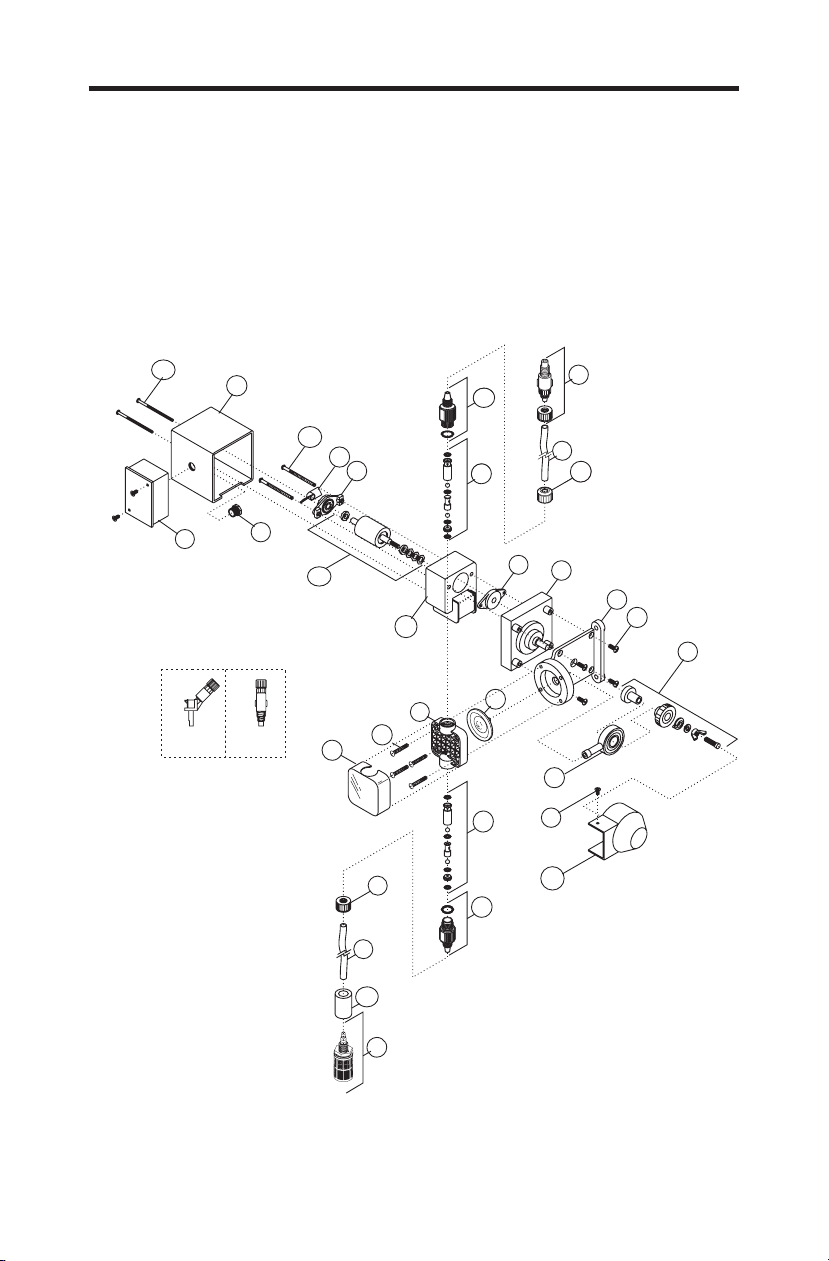
Catalog No. Description Amount Reqd.
1. C-395-6V Injection valve 6 PSI, Viton 1
C-395-6E Injection valve 6 PSI, EP (optional) 1
2. C-335-6 Discharge Tubing 3/8 OD, 5ft. Opaque Poly-E 1
3. C-330-6 Tube Nut 2
4. K-568V-4 Bullet valve (double ball), Viton, 4 pack set 2
K-568V-10 bullet valve (double ball), Viton, 10 pack set 2
K-569E-4 Bullet valve (double ball), EP, 4 pack set (optional) 2
K-569E-10 Bullet valve (double ball), EP, 10pack set(optional) 2
5. C-334-6 Suction tubing 3/8’ OD, 5ft. Clear PVC w/ indicator 1
6. C-346 Ceramic weight 1
7. C-345V Foot valve / strainer Poly-Pro, Viton 1
C-345E Foot valve / strainer Poly Pro, EP (optional) 1
8. C-535 Heavy duty molded pump head 1
9. C-504HD Screw, HD Pump head 10-32 x 1-1/4’ 4
10. C-535FC Pump head cover, Chem feed logo 1
11. C-628 Cover screw 6-32 x 2-3/4’ Steel 2
12. C-608P Motor Cover 1
13. C-625 Motor screw 8-32 x 2-1/2’ 2
14. C-612F Rotor Fan 1
15. C-612PB Rotor Bearing 2
16. C-616PN Rotor w/ Spacer 1
17. C-618P-14 Gearbox Assembly, 14 RPM 1
C-618P-30 Gearbox Assembly, 30 RPM 1
C-618P-45 Gearbox Assembly, 45 RPM 1
C-618P-60 Gearbox Assembly, 60 RPM 1
C-618P-125 Gearbox Assembly, 125 RPM 1
C-618P-250 Gearbox Assembly, 250 RPM 1
18. C-301 Motor Mount 1
19. C-624 Motor Mount Screw 10-32 x ½’ 4
20. C-325 Cam S/A C-600 1
21. C-304 Yoke w/Bearings 1
22. C-406T Diaphragm Teflon coated, EP 1
23. 90011-155 Screw 6-332 x 3/8’ 1
24. 90002-201 Cam Cover 1
25. C-550-6V Bullet Valve Adapter, Viton O-ring 2
C-560-6E Bullet Valve Adapter, EP O-ring 2
26. 90007-515 ½” Aluminum Chase Nipple 1
27. C-308J Junction Box Complete w/Cover and Gasket 1
28. C-615P-1 Stator S/A 115V/60Hz, blue-black (lead wires) 1
C-615P-2 Stator S/A 230V/60Hz, red-black (lead wires) 1
C-615P-3 Stator S/A 220V/50Hz, brown-blue (lead wires) 1
C-615P-4 Stator S/A 24V/60Hz, blue-white (lead wires) 1
C-615P-6 Stator S/A 230V/60Hz, red-yellow (lead wires) 1
C-615P-8 Stator S/A 220V/50Hz, brown-yellow (lead wires) 1
C-615P-9 Stator S/A 115V/60Hz, blue-yellow (lead wires) 1