Blue-White industries CHEM-FEED C-1500N User manual

MODEL C-1500N
5300 Business Drive
Huntington Beach, CA 92649
USA
Phone: 714-893-8529 FAX: 714-894-9492
www.Blue-White.com
INJECTOR
®
DISCHARGELINESMAYBE UNDER
HIGHPRESSURE.USECARE TO
PROTECTYOURSELFWHEN
DISCONNECTING.
CAUTION
ADJUSTWHILE RUNNING
MIN
1
2
3
45
6
7
8
9
LOOSENTHELOCKSCREW
TURNKNOBTODESIREDSETTING
RE-TIGHTENTHELOCKSCREW
MAX
CHEM-FEED
BLUE-WHITEINDUSTRIES
WESTMISNSTER
CA 92683
Blue-White
Industries, Ltd.
R

TABLE OF CONTENTS
SECTION HEADING PAGE
1Introduction 2
2Specifications 2
3C-1500N Features 3
4How to install the C-1500N 3
4.1 Mounting location 3
4.2 Electrical connections 5
4.3 How to install the tubing and fittings 6
5How to operate the C-1500N 8
5.1 Adjusting the Pump Output - Standard Models 8
5.2 Adjusting the Pump Output - Fixed cycle timer Models 9
5.2 Measuring the pump’s output - volumetric test 9
6How to maintain the C-1500N 9
6.1 Routine inspection and cleaning 9
6.2 How to clean the C-1500N 9
1.0 Introduction
Thank you for purchasing the C-1500N positive displacement metering pump.
The C-1500N is designed to inject chemicals into piping systems. All models are
equipped with a top mounted mechanical flow rate adjustment knob. Optional
on/off cycling timers are available.
The pump has been tested by NSF International for use with 12-½% Sodium
Hypochlorite.
CAUTION: This pump has been evaluated by ETL Intertek Testing Services for
use with water only. The factory performance tests the pump with water only.
2.0 Specifications
Maximum Working Pressure 125 psig / 8.6 bar*
o o
Maximum Fluid Temperature 130 F / 54 C
o
Output Accuracy +/- 10% of maximum (water @ 70 F, 0
psig, and 5’ suction lift)
o o
Ambient Temperature Range 14 to 110 F / -10 to 43 C
Enclosure NEMA 3R (IP 23) acceptable for outdoor
use
Duty Cycle Continuous
Maximum Viscosity 1,000 Centipoise
Maximum Suction Lift up to 10 ft. water
Power Requirements 115V60Hz 45 Watts
220V50Hz 45 Watts
230V60Hz 45 Watts
24V60Hz 45 Watts
Dimensions 9-1/16” high x 4-1/2” wide x 5-3/4” deep
Weight 7 lb.
C-1500N Page 2

C-1500N Page 3
3.0 C-1500N Features
!Double-ball ceramic check valves.
!PVDF (Kynar) valve assemblies.
!Viton o-rings.
!High outlet pressure capability of 125 PSIG.*
!Easy access, top mounted mechanical feed rate adjustment.
!Ball bearing supported motor drive shaft.
!Permanently lubricated ball bearing motor.
!20:1 adjustment turn down ratio.
!Acceptable for outdoor use. (NEMA 3R; IP23)
!Corrosion resistant Valox housing.
!Easy servicing.
!Includes suction tube foot valve & strainer, suction tube weight, suction tubing,
discharge tubing and injection fitting with internal back-flow check valve and
mounting hardware. * Most models.
4.0 How To Install the C-1500N
Note: All diagrams are strictly for guideline purposes only. Always consult
an expert before installing the C-1500N into specialized systems.
The C-1500N should be serviced by qualified persons only.
4.1 Mounting Location
Choose an area located near the chemical supply tank, chemical injection point
and electrical supply. Although the pump is designed to withstand outdoor
conditions, a cool, dry, well ventilated location is recommended. Install the
pump where it can be easily serviced.
!Mount the pump to a secure surface or wall using the enclosed hardware. Wall
mount to a solid surface only. Mounting to drywall with anchors is not
recommended.
!Keep the outlet (discharge) tubing as short as possible. Longer tubing
increases the back pressure at the pump tube.
!Do not mount the pump directly over your chemical container. Chemical
fumes may damage the unit. Mount the pump off to the side or at a lower
level than the chemical container.
!Mounting the pump lower than the chemical container will gravity feed the
chemical into the pump. This “flooded suction” installation can reduce the
time required to prime the pump. Install a shut-off valve, pinch clamp or other
means to halt the gravity feed to the pump during servicing.
!Your solution tank should be sturdy. Keep the tank covered to reduce fumes.
!Be sure your installation does not constitute a cross connection with the
drinking water supply. Check your local plumbing codes.
Proper eye and skin protection must be worn
when installing and servicing the pump.
!CAUTION

#10-32
FIG. 4.2 SWIMMING POOL INSTALLATION
FIG. 4.3 TYPICAL INSTALLATION
®
1. Strainer Blue-White F-300
2. Circulation Pump 7. Injector
®
3. Filter Blue-White C-1500N
4. Heater 8. Solution Tank
5. Check Valve 9. Injection Fitting
6. Flowmeter 10. Return Line
1
Pool
235
4 6 7
8
9
10
Discharge Tube
Pumping unit
Suction Tube
(vertical)
Chemical
Container
¼" & ½" NPT Injector
C-1500N
4-1/2”
9-1/16”
5-3/4”
FIG. 4.0 DIMENSIONAL DRAWING FIG. 4.1 INJECTOR WALL MOUNTING
#10 Self-Tap
(2 X)
Wall Mount
Bracket
C-1500N Page 4
Risk of chemical overdose. Be certain the
pump does not overdose chemical during
backwash and periods of no flow in the
circulation system.
!WARNING
To prevent chemical overdosing, a flow switch
is recommended on the circulation system to
automatically stop chemical feed when there is
no return flow to the swimming pool or spa.
!CAUTION

1
235
46 7
8
9
10
C-1500N Page 5
4.2 Electrical Connections
4.2.1 Input Power Connections
Note: When in doubt regarding your electrical installation, contact a licensed
electrician.
The C-1500N is supplied with either a ground wire conductor and a grounding
type attachment plug (power cord) or a junction box for field wiring.
POWER CORD MODELS -To reduce the risk of electric shock, be certain
that the power cord is connected only to a properly grounded, grounding type
receptacle.
JUNCTION BOX MODELS -To reduce the risk of electric shock, be certain
that a grounding conductor is connected to the green grounding conductor
located in the junction box.
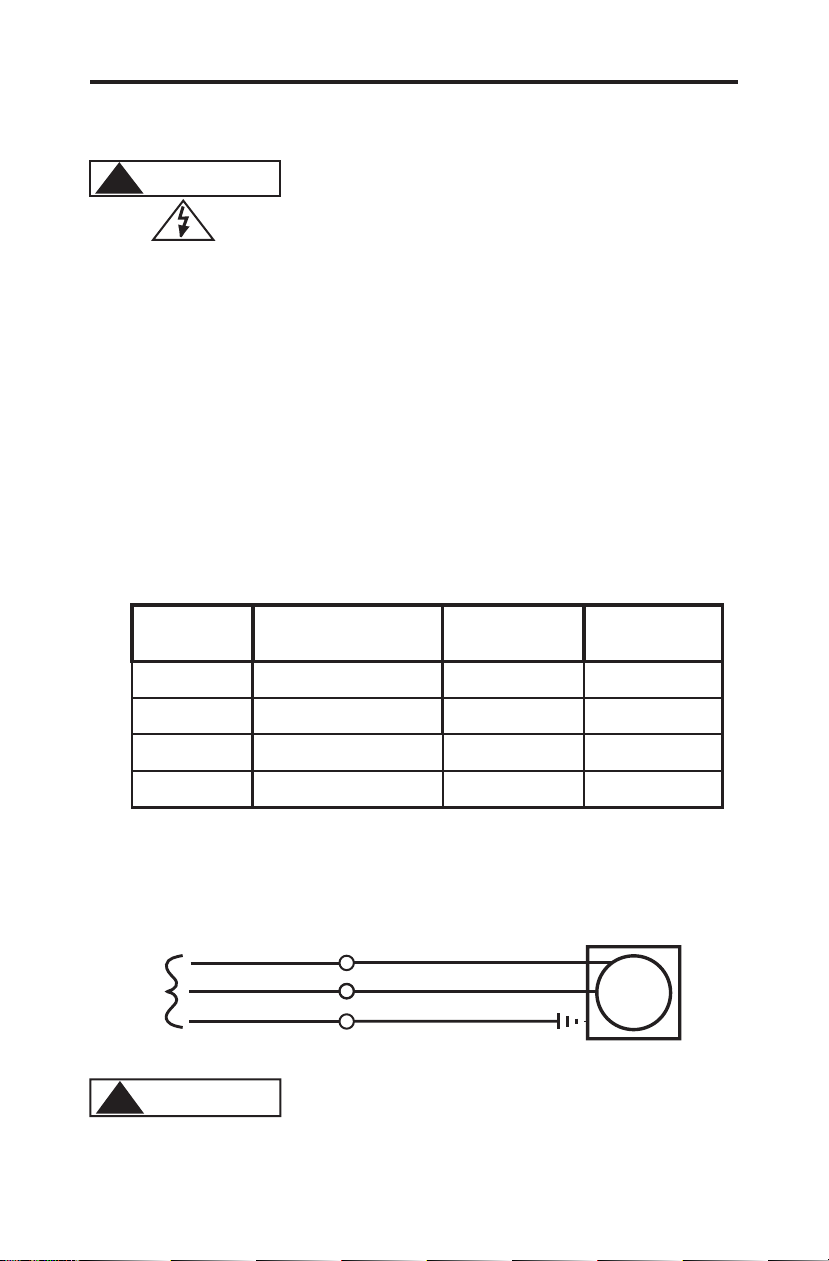
FIG. 4.4 WIRING DIAGRAM - STANDARD MODELS
AC
MOTOR
INPUT
VOLTAGE
115V 60Hz
HOT
LEADWIRE
NEUTRAL
LEADWIRE
GROUND
LEADWIRE
230V 60Hz
BLUE or YELLOW
BLUE
BROWN
RED
GREEN
GREEN
GREEN
MOTOR LEADWIRES
Neutral
Hot
Ground (green)
Earth Ground (green)
Common
Hot
AC
Input
Power
220V 50Hz
BLACK or YELLOW
BLACK or YELLOW
* Yellow leadwire : thermally protected motor
Black or Blue leadwire: standard impedance protected motor
*
*
*
24V 60Hz
WHITE
GREEN
BLUE
*
To prevent chemical overdosing,
disconnecting power to the circulation system
must also disconnect power to the pump.
!CAUTION
SHOCK
!WARNING
Risk of electric shock. Be certain to connect the
pump to the proper supply voltage. Using the
incorrect voltage will damage the pump and
may result in injury. The voltage requirement is
printed on the pump serial label.

4.3 How To Install the Tubing and Fittings
4.3.1 Inlet Tubing - Locate the inlet fitting of the pump head, see fig 4.6. Remove the
tube nut. Push the clear PVC suction tubing onto the compression barb of the
fitting. Use the tube nut to secure the tube. Hand tighten only.
4.3.2 Footvalve/Strainer -Trim the inlet end of the suction tubing so that the strainer
will rest in a vertical position, approximately one inch from the bottom of the
solution tank. This will prevent sediment from clogging the strainer. Loss of
prime may occur if the footvalve is permitted to lay on the bottom of the solution
tank in a horizontal position. Slip the ceramic weight over the end of the suction
tube. Press the footvalve/strainer into the end of the tube. Secure the ceramic
weight to the strainer. Drop the strainer into the solution tank.
4.3.3 Outlet Tubing - Locate the outlet fitting of the pump head, see fig 4.6. Remove
the tube nut. Push the opaque outlet (discharge) tubing onto the compression barb
of the fitting. Use the tube nut to secure the tube. Hand tighten only.
Trim the other end of the outlet tube leaving only enough slack to connect it to the
Injection/Check valve Fitting (see below). Increasing the length of the outlet tube
increases the back pressure at the pump head, particularly when pumping viscous
fluids.
Keep the inlet and outlet tubes as short as possible.
FIG. 4.5 WIRING DIAGRAM - FIXED TIMERS
(factory Setting)
Cycle Adjustment
Potentiometer
T3
T2
T1 AC
Input
Power
Hot
Common
Ground (green)
Timer
Board
Hot
Neutral
AC/LOAD
AC
LOAD
JB2 JB3
JB1
AC
Motor
JB1, JB2, JB3 = Voltage Selector Jumpers
Jumpers Configuration
Install JB2 & JB3, (JB1 left open) = 24 V AC input
Install JB1 & JB3, (JB2 left open) = 115 V AC input
Remove all jumpers (JB1, JB2, & JB3 left open) = 220V, 230 V AC input
C-1500N Page 6
Proper eye and skin protection must be worn
when installing and servicing the pump.
!CAUTION

FootValve Assembly
Must be installed in
a vertical position.
DO NOT LAY ON SIDE!
Ceramic
Weight
Suction Tubing
Footvalve Adapter
O-Ring
Ceramic Ball
O-Ring
Footvalve Body
Footvalve Strainer
Discharge Tube
(Rigid P.E.)
Outlet Adapter
Tube Nut
Inlet Adapter
Tube Nut
Suction Tubing
(clear PVC)
Pump Head
FootValve
FIG. 4.6 FIG. 4.7 FOOTVALVE ASSY.
4.3.4 Injection/Check Valve Fitting Installation - The Injection/Check valve
fitting is designed to install directly into either 1/4” or 1/2” female pipe
threads.
Install the Injection/Check valve directly into the tee fitting. Do not install the
fitting into a pipe stud and then into the tee. The solution must inject directly
into the flow stream.
Use Teflon thread sealing tape on the pipe threads. Push the opaque outlet
(discharge) tubing onto the compression barb of the Injection/Check valve
fitting. Use the tube nut to secure the tube. Hand tighten only.
Injection/Check valve fitting fitting will require periodic cleaning, especially
when injecting fluids that calcify such as sodium hypochlorite. These lime
deposits and other build ups can clog the fitting increasing the back pressure
and interfering with the check valve operation. See section 6.0.
FIG. 4.8
INJECTION/CHECK VALVE
TEE INSTALLATION AND EXPLODED VIEW
C-1500N Page 7

5.0 How To Operate The C-1500N
5.1 Adjusting the Pump Output- Standard models (fig. 5.1) - The C-1500N
flow rate can be adjusted within a range of 5% -100% of maximum output (20:1
turndown ration) by means of a mechanical, cam type mechanism. The mecha-
nism adjusts the pump’s stroke length to an infinite number of settings within the
flow range. Because the pump’s output is reduced by increasing the pressure of
the system being injected into, the amount of suction lift, and the viscosity of the
fluid being injected, the pump must be over-sized to allow for these factors.
Sizing the pump to allow adjustment within the midrange is preferred to maintain
accuracy. Consult the factory for individual pump model output curve data.
To adjust the pump’s output:
1. With the pump running, loosen the set screw.
2. Turn the adjustment knob to the desired setting.
3. Re-tighten the set screw.
CAUTION
ADJUST WHILE RUNNING
DISCHARGE LINES MAY BE UNDER
HIGH PRESSURE. USE CARE TO
PROTECT YOURSELF WHEN
DISCONNECTING.
MAXMIN
1
2
3
456
7
8
9
LOOSEN THE LOCK SCREW
TURN KNOB TO DESIRED SETTING
RE-TIGHTEN THE LOCK SCREW
5.2 Adjusting the Pump Output - DELUXE Models (fig. 5.2)
In addition to the cam type mechanism adjustment (section 5.1), the pump output
of the C-1500N deluxe unit equipped with an optional electronic cycle timer
board can also be fine tuned by adjusting the timer adjustment knob. The total-
time cycle is factory preset and is not user adjustable. The on-time cycle is
adjustable from 5% to 100% of the total cycle time. Example: If the total-time
cycle is 5 seconds and the on-time cycle is adjusted for 20 percent, the pump will
run for 1 second and turn off for 4 seconds (5 second total cycle). This cycle is
repeated until either the cycle time is changed or the input power is disconnected
from the pump.
Note: When the input power is disconnected from the C-1500N, the unit will
maintain the last adjusted settings. When power is restored to the pump, the
C-1500N will begin to pump using the last time cycle setting.
Junction Box
Cycle Timer
Adjustment Knob
FIG. 5.2
To adjust the On-Time :
Turn the timer adjustment knob
located on the junction box
cover.
Clockwise increases the time on.
FIG. 5.1
Adjustment Knob
(Cam Type Mechanism)
C-1500N Page 8

5.3 Measuring the Pump’s Output - Volumetric Test.
This volumetric test will take into account individual installation factors such
as line pressure, fluid viscosity, suction lift, etc. This test is the most accurate
for measuring the injector’s output in an individual installation.
1. Be sure the Injection Fitting and Footvalve/Strainer is clean and working
properly.
2. With the injector installed under normal operating conditions, place the
Footvalve/Strainer in a large graduated cylinder.
3. Fill the graduated cylinder with the solution to be injected and run the
injector until all air is removed from the suction line and the solution enters
the discharge tubing.
4. Refill the graduated cylinder, if necessary, and with the Footvalve com-
pletely submerged in the solution, note the amount of solution in the graduated
cylinder.
5. Run the injector for a measured amount of time and note the amount of fluid
injected. A longer testing time will produce more accurate results.
6.0 How to Maintain the C-1500N
6.1 Routine Inspection and Maintenance
The C-1500N requires very little maintenance. However, the pump and all
accessories should be checked regularly. This is especially important when
pumping chemicals. Inspect all components for signs of leaking, swelling,
cracking, discoloration or corrosion. Replace worn or damaged components
immediately. Cracking, crazing, discoloration and the like during the first week
of operation are signs of severe chemical attack. If this occurs, immediately
remove the chemical from the pump. Determine which parts are being attacked
and replace them with parts that have been manufactured using more suitable
materials. The manufacturer does not assume responsibility for damage to the
pump that has been caused by chemical attack.
6.2 How to Clean the C-1500N
The C-1500N will require occasional cleaning, especially the Injection fitting,
the Footvalve/Strainer, and the pump head valves. The frequency will depend
on the type and severity of service..
]
When changing the diaphragm, the pump head chamber and pump head cover
should be wiped free of any dirt and debris.
]
Periodically clean the injection/check valve assembly, especially when injecting
fluids that calcify such as sodium hypochlorite. These lime deposits and other
build ups can clog the fitting, increase the back pressure and interfere with the
check valve operation. See section 4.3.4. Fig. 4.8.
]
Periodically clean the suction strainer. Fig.4.7
]
Periodically inspect the air vents located under the motor compartment and under
the pump head. Clean if necessary.
C-1500N Page 9
Proper eye and skin protection must be worn
when installing and servicing the pump.
!CAUTION

45
42
44
43
9
10
8
12
13
15
13
12
14
14
16
17
19
18
20
21
22
29
32
33
30
31
34
35
37
38
39
41
40
46
47
48
49
50
48 51
52
53
54
55
25
CAUTION
ADJUSTWHILERUNNING
DISCHARGELINESMAYBEUNDER
HIGHPRESSURE.USECARETO
PROTECTYOURSELF WHEN
DISCONNECTING.
MIN
1
2
3
45
6
7
8
9
LOOSENTHELOCKSCREW
TURNKNOBTODESIREDSETTING
RE-TIGHTENTHELOCKSCREW
MAX
7
11
24
1
Replacement Parts Drawing
C-1500N Page10

Item Part No Description Qty
C-1500N PARTS LIST
1 C-535A6-6 Pumphead Kit, HDN Viton 1
C-535A6-6E Pumphead Kit, HDN EP 1
7 71000-324 FootValve S/A, C-340V, VT 1
71000-325 FootValve S/A, C-340E, EP 1
8 90008-068 Ceramic weight, C-346 1
9 70004-074 Cover P/Head, HD Chem-Feed logo 1
70004-071 Cover P/Head, HD Noir logo 1
70004-086 Cover P/Head, HD Micro logo 1
10 90011-141 Screw 10-32 x 1.25 4
11 70000-638 Tube Indicator Glass 3/8 x 5FT 1
76000-171 Tube Suction 1/4 x 5FT 1
12 90002-077 Tube Nut, .25T, P.P. 2
90002-047 Tube Nut, .37T, P.P. 2
13 71000-204 Adapter S/A Bullet .37T Viton 2
71000-205 Adapter S/A Bullet .37T EP 2
71000-224 Adapter S/A Bullet .37T Silicon 2
71000-225 Adapter S/A Bullet .25T Viton 2
71000-226 Adapter S/A Bullet .25T EP 2
71000-227 Adapter S/A Bullet .25T Silicon 2
14 71000-195 Cartridge Bullet Valve S/A, Double-Ball 2
15 90002-146 P/Head Noir Molded, P.P. 1
16 76000-168 Tubing D/Charge, 3/8 x 5FT 1
76000-169 Tubing D/Charge, 1/4 x 5FT. 1
17 70000-683 Diaphragm S/A 2.0 15N, Viton/TFE 1
70000-682 Diaphragm S/A 2.0 15N, EP/TFE 1
71000-058 Diaphragm S/A 1.6 15N, Viton/TFE 1
71000-057 Diaphragm S/A 1.6 15N, EP/TFE 1
18 90006-006 Return Spring 2
19 76000-172 Stirr-up 1
20 90002-001 Slide Bearing 2
21 90001-132 Offset Cam #1 .125” 1
90001-133 Offset Cam #2 .055” 1
90001-134 Offset Cam #3 .187” 1
90001-141 Offset Cam #4 .100” 1
22 90002-017 Dial Knob 1
24 90011-168 Screw #6 x .62 PH oval ‘A’ 4
25 C-1503N-3 Top Cover Assembly with bearing 1
29 70000-131 Drive Cam S/A #1 .125” 1
70000-133 Drive Cam S/A #2 .055” 1
70000-132 Drive Cam S/A #3 .187” 1
70000-722 Drive Cam S/A #4 .100” 1
C-1500N Page 11

30 90011-122 Screw 10-32 x .50 PHL PAN 1
31 90002-106 Bracket Wall Mount 1
32 90011-014 Spacer, Rotor 1
33 90011-122 Screw 10-32 x .50 PHL PAN 4
34 76000-530 Motor Mount, Large Diaphragm 1
76001-171 Motor Mount, Small Diaphragm 1
35 90008-138 Plug .312 Hole Black 1
36 90006-597 Gasket, Motor Mount 1
37 76000-630 Slide Clamp 2
38 C-1501NR Motor Cover for power cord models 1
C-1508PN-2 Motor cover for junction box models 1
39 90003-513 Bumper Feet 4
40 70000-589 Connector Liq-Tite w/nut 1
41 90010-110 Cord 18/3 SJTW/A 115V, U.S., NEMA 5/15 plug 1
90010-128 Cord 18/3 SJTW/A 220V, Euro, CEE 7/VII (A) plug 1
90010-133 Cord 18/3 SJTW/A 230V, U.S., NEMA 6/15 plug 1
42 71000-133 Cover, Junction Box with Gasket and Label 1
43 90007-515 Bushing, Junction Box Connector, Alum. 1
44 76000-522 Junction Box, Valox 1
45 90011-129 Screw, Cover, 6-32 X .25 Phil Pan SS Black 2
46 90006-598 Fan, 1.80” Diameter, Alum. 1
47 90011-022 Screw, Motor, 8-32 X 2.5” Phillips Steel 2
48 70000-028 Bearing Bracket With Bearing 2
49 70000-027 Rotor Assembly With Shaft And Spacers 1
50 70000-018 Stator S/A, 115V60Hz Standard Blue-Black 1
70000-019 Stator S/A, 115V60Hz Thermal Brown-Blue 1
71000-019 Stator S/A, 220V50Hz Standard Brown-Black 1
71000-020 Stator S/A, 220V50Hz Thermal Brown-Yellow 1
70000-020 Stator S/A, 230V60Hz Standard Red-Black 1
70000-021 Stator S/A, 230V60Hz Thermal Red-Yellow 1
70000-072 Stator S/A, 24V60Hz Standard Blue-White 1
51 90011-024 Ground Screw 8-32 x .25 Hex SL ST 1
52 90010-127 Lead Wire, ground, Green 1
53 90011-078 Washer, Ground Screw, #8 Intrl/Star 1
54 71000-268 Gearbox, 14 RPM 1
71000-269 Gearbox, 30 RPM 1
71000-270 Gearbox, 45 RPM 1
71000-271 Gearbox, 60 RPM 1
71000-272 Gearbox, 125 RPM 1
71000-273 Gearbox, 250 RPM 1
55 70000-439 Injection Valve S/A 37T VIT 1/2 PSI 1
(N/s) 90010-153 Cycle Timer 5 Sec. 24V-115V-230V 50/60 Hz 1
(N/s) 90010-151 Cycle Timer 1 Min. 24V-115V-230V 50/60 Hz 1
Item Part No Description Qty
Users of electrical and electronic equipment (EEE) with the WEEE marking per Annex IV of
the WEEE Directive must not dispose of end of life EEE as unsorted municipal waste, but
use the collection framework available to them for the return, recycle, recovery of WEEE
and minimize any potential effects of EEE on the environment and human health due to the
presence of hazardous substances. The WEEE marking applies only to countries within the
European Union (EU) and Norway. Appliances are labeled in accordance with European
Directive 2002/96/EC.
Contact your local waste recovery agency for a Designated Collection Facility in your area.


LIMITED WARRANTY
Your new pump is a quality product and is warranted to be free of defects as set down in this policy. All parts, including
rubberized goods, and labor are covered under warranty for 90 days from the date of purchase. Used peristaltic pump
tube assemblies are not warranted. Parts, excluding rubberized goods, are covered under warranty for 12 months from
the date of purchase.
Warranty coverage does not include damage to the pump that results from misuse, carelessness, abuse or alteration.
Only the repair or the replacement of the pump is covered. Blue-White Industries does not assume responsibility for
any other loss or damage.
Warranty status is determined by the pump’s serial label and the sales invoice or receipt. The serial label must be on the
pump and the pump must be accompanied by the sales invoice or receipt to obtain warranty coverage. The warranty
status of the pump will be verified by Blue-White or a factory authorized service center.
Please be advised; injection and metering devices are not intended as a means of treating water to render it suitable for
human consumption. When used as hypochlorinators, they are meant to destroy bacteria and algae contamination,
before it’s removal by filtration. Acid and soda injectors are used for PH control (balance). Blue-White injectors are
factory tested with water only for pressure and performance. Installers and operators of these devices must be well
informed and aware of the precautions to be taken when injecting various chemicals -especially those considered
hazardous or dangerous.
Should it become necessary to return an injector for repair or service, you must attach information regarding the
chemical used as some residue may be present within the unit which could be a hazard to service personnel.
Blue-White Industries will not be liable for any damage that may result by the use of chemicals with their injectors and
it’s components. Thank you.
PROCEDURE FOR IN WARRANTY REPAIR
Carefully pack the pump to be repaired, include the foot strainer and injection/check valve fitting. Enclose a brief
description of the problem as well as the original invoice or sales receipt showing the date of purchase. The receipt will
be returned with the unit. Prepay all shipping costs. COD shipments will not be accepted. Warranty service must be
performed by the factory or an authorized service center. Damage caused by improper packaging is the responsibility of
the sender.
AUTHORIZED SERVICE CENTERS
ARKANSAS FLORIDA
BT Environmental, Inc AAA Electric Motor Services NEW YORK
Bill Thomason 1131 N.E. 45th Street Sherwood Specialties, Inc.
225 Castleberry Street Ft. Lauderdale, FL 33334 875 Atlantic Ave. ‘B’
Hot Springs, AR 71901 954-772-7501 Rochester, NY 14609
501-624-3837 585-546-1211
Rice Pump & Motor Repair
CALIFORNIA (NORTHERN) 5740 Powerline Road NORTH CAROLINA
Howard E. Hutching company Ft. Lauderdale FL 33309 Southern Industrial Sales
(Repair Center) 954-776-6049 1903 Herring Avenue
7190 Penryn Plaza American Pump Wilson, NC 27893
Penryn, CA 95663 7580-A W. Tennessee St. 800-872-7665
800-568-3958 Tallahassee, FL 32304
Swimco Electric Co. 850-575-9618 SOUTH DAKOTA
753 Camden Avenue Son-Aqua Distributing
Jerry Lee Chemical Co.
Campbell, CA 95008 Jim Robinson
3407 W. Old Fairfield Drive
408-378-2607 2447 W. Main Street
Pensacola, FL 32505 Rapid City, SD 57702
CALIFORNIA (SOUTHERN) 904-432-9929 605-343-7716
Blue-White Industries
(Repair Center) Picard Chemical TENNESSEE
5300 Business Drive 1670 S. Congress Avenue Rock City Machine
Huntington Bch. CA 92649 W. Palm Beach, FL 33406 307 3rd Avenue South
714-893-8529 561-965-3434 Nashville, TN 37201
COLORADO 615-244-1371
ILLINOIS
Denver Winpump Mullarkey Associates
5754 Lamer ave (Repair Center)
.Arvada, CO 80002 TEXAS
12346 S. Keeler Ave.
303-424-3551 Alamo Water Refiners
Alsip, IL 60658 13700 Hwy. 90 West
CONNECTICUT 708-597-5558 San Antonio, TX 78245
Cronin-Cook & Associates 210-677-8400
24 West Road MARYLAND
Vernon, CT 06029 Century Pool Service, Inc Shelter’s Water Refining
860-875-0544 5020 Nicholson Court, #201 Robert Shelton
Kensington, MD 20895 2708 E. Randol Mill Rd.
301-231-8999 Arlington, TX 76011
817-640-6188
880000-137 12/4/2007
Table of contents
Other Blue-White industries Laboratory Equipment manuals
Popular Laboratory Equipment manuals by other brands

Chopin
Chopin Alveo PC graph Quick installation and first test

Thermo Scientific
Thermo Scientific TSQ Endura Hardware manual

Medite
Medite USE 33 Installation & operation manual

Bruker
Bruker minispec TC3 user manual

Fisher Scientific
Fisher Scientific accuSpin 3 operating instructions

Stereotaxis
Stereotaxis Niobe PM3.1 Installation Verification and Testing