5.4 Measuring the Pump’s Output - Volumetric Test.
This volumetric test will take into account individual installation factors
such as line pressure, fluid viscosity, suction lift, etc. This test is the most
accurate for measuring the injector’s output in an individual installation.
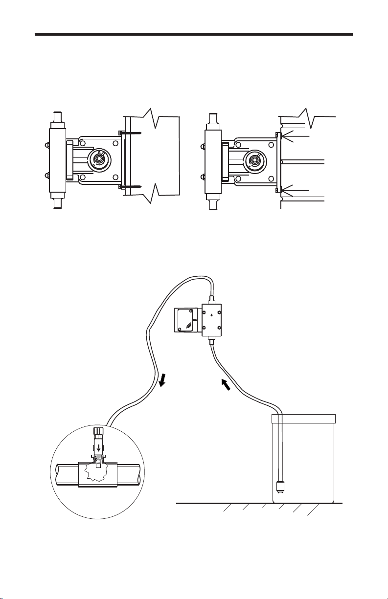
1. Be sure the Injection Fitting and Footvalve/Strainer is clean and
working properly.
2. With the injector installed under normal operating conditions, place
the Footvalve/Strainer in a large graduated cylinder.
3. Fill the graduated cylinder with the solution to be injected and run the
injector until all air is removed from the suction line and the solution
enters the discharge tubing.
4. Refill the graduated cylinder, if necessary, and with the Footvalve
completely submerged in the solution, note the amount of solution in the
graduated cylinder.
5. Run the injector for a measured amount of time and note the amount
of fluid injected. A longer testing time will produce more accurate results.
6.0 How to Maintain the Pump
6.1 Routine Inspection and Maintenance
The Pump requires very little maintenance. However, the pump and all
accessories should be checked regularly. This is especially important
when pumping chemicals. Inspect all components for signs of leaking,
swelling, cracking, discoloration or corrosion. Replace worn or damaged
components immediately.
Cracking, crazing, discoloration and the like during the first week of
operation are signs of severe chemical attack. If this occurs, immediately
remove the chemical from the pump. Determine which parts are being
attacked and replace them with parts that have been manufactured using
more suitable materials. The manufacturer does not assume responsibil-
ity for damage to the pump that has been caused by chemical attack.
6.2 How to Clean the Pump
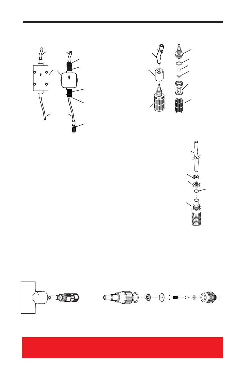
The Pump will require occasional cleaning, especially the Injection fitting,
the Footvalve/Strainer, and the pump head valves. The frequency will
depend on the type and severity of service. When changing the dia-
phragm, the pump head chamber and pump head cover should be wiped
free of any dirt and debris. Periodically clean the injection/check valve
assembly, especially when injecting fluids that calcify such as sodium
hypochlorite. These lime deposits and other build ups can clog the fitting,
increase the back pressure and interfere with the check valve operation.
Periodically clean the suction strainer. Periodically inspect the air vents
located on the back of the motor compartment and under the pump head.
Clean if necessary.
CAUTION: PROPER EYE AND SKIN PROTECTION MUST BE WORN
WHEN INSTALLING AND SERVICING THE METERING PUMP
Page 10 Page 11
C-600 C-600
5.0 How To Operate The Pump
5.1 Adjusting the Pump Output
The flow rate can be adjusted within a range of approximately 10%-100% of
maximum output (27:1 turndown ratio) by means of a mechanical, cam type
mechanism. The mechanism adjusts the pump’s stroke length to 1 of 27 settings
within the flow range. The pump’s output is affected by the pressure of the
system , the amount of suction lift, and the viscosity of the fluid being injected
into the pump must be over-sized to allow for these factors. Sizing the pump to
allow adjustment within the midrange is preferred to maintain accuracy. Consult
the factory for individual pump model output curve data.
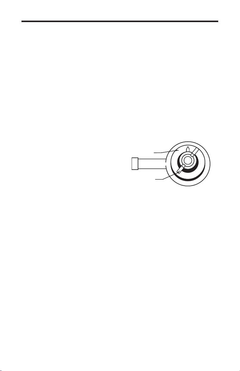
5.2 To adjust the pump output:
1. Make sure the pump is off before adjusting.
2. Loosen the wing nut.
3. Turn adjusting knob so the pointer is on the desired setting. Note: pump less
chemical at first, then re-adjust.
4. While holding the knob, tighten the wing nut to keep the knob at the desired
setting. Note: wing nut must be tight.
5.3 Priming The Pump
Each pump is factory tested with water. The test water is sealed in the pump
head keeping the valves dry to aid in priming. If the valves have dried or priming
is difficult due to back pressure, do the following:
1. Remove the opaque discharge tubing from the top valve fitting in the
pumphead.
2. Remove the top and bottom valve fittings and immerse in water to wet the
valves. Reinstall the fittings.
3. With the discharge tubing removed, start the pump. Stop the pump when the
fluid enters the pumphead.
4. Attach the discharge tubing to the top valve fitting.
5. Be sure the footvalve/strainer is attached to the suction tubing and is installed
in a vertical position.
If your installation is at high altitude, priming may be more difficult since the
atmospheric pressure is decreased. When the suction line is dry, the diaphragm
may not create enough pull. If this is the case, do the following:
1. Remove the clear suction tube from the bottom valve fitting and fill completely
with water.
2. While the pump is running, attach the tube (filled with water) to the bottom
valve fitting.
3. When the fluid enters the pumphead, place the foot valve in the solution tank.
4. Be sure the footvalve/strainer is attached to the suction tubing and is installed
in a vertical position.
6
0
1
2
3
4
5
Adjustment Knob
Wing Nut
FIG. 5.1 Adjustment Cam


 user manual")
