Bluebell BC364 User manual

Operation Guide
BC364
Multi-format interface
Ref: BC364-OperationGuide-v1
BC364
LED A
LED B
SET UP
SFP2 SFP1

BC364-OperationGuide-v1 2
Bluebell Opticom Ltd.
Unit 2, The Quadrant
Howarth Road
Maidenhead
Berkshire
SL6 1AP
United Kingdom
Tel: +44 (0) 1628 510055 / Fax: +44 (0) 1628 510057
Pleasenotethatalldocumentationhereinisofaconfidentialnatureandmaynotbereproduced
without written confirmation from Bluebell Opticom Ltd. The technical descriptions are to
aid service and repair only. Dissemination to a third party or parties will constitute breach of
copyright.
Information in this document is subject to change without notice and does not represent a
commitment on the part of Bluebell Opticom Ltd.
Bluebell Opticom Ltd. has taken all possible steps to ensure that the information given here
is both correct and complete. In no event can Bluebell Opticom Ltd. accept any liability or
responsibility for any loss or damage to the owner of the equipment, any third party, or any
equipment which may result from use of this manual or the equipment which it describes.
Declaration of Conformities
Bluebell Opticom Ltd. hereby declares that the BC364 Fibre Optic Transmission Equipment is
in compliance with the essential requirements and other relevant provisions of the following
EU directives:
EMI/RFI: 89/336/EEC, EN55022B, EN61000-4-11, EN61000-4-4 (Level 2),
EN61000-4-4FTB, EN61000-4-2, EN61000-4-5
Electrical: EN61000-6-1, EN61000-6-2, EN61000-6-3, EN61000-6-4
Class 1 Laser Safety Compliant
RoSH and WEEE declaration
Bluebell Opticom Ltd. complies with EU RoSH Directive 2002/95/EC, which restricts the use of
substances hazardous to humans and their environment in the manufacture of electrical and
electronic equipment.
The “crossed out wheelie bin” symbol on the enclosures and represented above is
there to remind users of the obligation of selective collection of waste. This label is
applied to various products to indicate that the product is not to be thrown away as
unsorted municipal waste. At the end of life, dispose of this product by returning it to the point
ofsale ortoyourlocal municipalcollection pointfor recycling ofelectric andelectronic devices.
Customer participation is important to minimize the potential effects on the environment and
humanhealth thatcan resultfrom hazardoussubstancesthat maybecontained inthis product.
Please dispose of this product and its packaging in accordance with local and national
disposal regulations, including those governing the recovery and recycling of waste electrical
and electronic equipment. Contact your local waste administration, waste collection company
or dealer.

BC364-OperationGuide-v1 3
Table of Contents
Contents
Overview ...................................................................................................... 4
Introduction..........................................................................................................................................4
Physical formats................................................................................................................................4
Power requirements ........................................................................................................................5
BC364 connections ......................................................................................6
The SET UP switch - BC364 operational configurations..................................8
Configuration 1 ..................................................................................................................................8
Configuration 2 ...............................................................................................................................10
Configuration 3 ...............................................................................................................................11
Configuration 4 ...............................................................................................................................12
Auto mode..........................................................................................................................................14
Operation with incorrect SFP cartridges...........................................................................15
SDI format compatibility ..............................................................................15
BC364 SFP combinations.........................................................................................................16
Other setup options......................................................................................................................17
External monitoring .....................................................................................19
BC100/160 Frame Panel LEDs..............................................................................................19
Monitoring via webpages...........................................................................................................19
Monitoring via SNMP.....................................................................................................................19
Appendix ....................................................................................................20
Specifications..................................................................................................................................20
SFP Options......................................................................................................................................21

BC364-OperationGuide-v1 4
Overview
Thank you for purchasing this Bluebell Opticom professional broadcast video product. If you
are new to Bluebell products, or to the subject of transmitting video and/or other types of signal
over fibre links, please take the time to read through this document before putting the BC364
to use.
Introduction
The BC364 plug-in module belongs to the range of Bluebell Opticom BC Series modular fibre
interfaces, designed primarily for Outside Broadcast (OB) and studio applications. The module
cansupporttwoindependent channels,withprimaryinput andoutputinthe formof SFPcarriers.
These will normally be fitted with fibre-optic cartridges of the user’s choice, though compatible
cartridges with coaxial or other types of connector may be installed if wished. Each channel
also has a second “copper” output in the form of a BNC socket.
The BC364 is a very versatile interface. The SFP carriers are capable of bidirectional
operation: when fibre-optic cartridges are fitted, various cartridge combinations - an input and
an output, two inputs, or two outputs - may be used. Also, the two channels may be configured
in several ways; these two factors allow the module to perform a variety of optical/optical and
optical/copper operations often needed in OB and other broadcast situations. Configuration
of the BC364 is selected by a front panel hex switch. The module’s flexibility is enhanced still
further by the interchangeability of SFP cartridge types.
The BC364 is intended for use with SDI video signals (3G, HD or SD), or with ASI video signals,
in situations where it is necessary to interface between two fibre-optic systems using different
fibre connectors. It can also be used as a “break-out” device, allowing a 3G-SDI video signal to
be “tapped-off” from a fibre link between two other locations. If non-fibre optic cartridges are
fitted into one of the I/O carriers, the module can act as a fibre-copper converter with a local
monitoring point.
Physical formats
BC364 modules fit the Bluebell BC100 or BC160 19” modular rack enclosures. The racks can
house fifteen (BC100) or six (BC160) interface modules, and are fitted with dual internal AC
power supplies.
Alternatively, modules may be fitted into smaller aluminium chassis; the BC101 and BC102
hold one and two modules respectively and require an external DC power source, while the
BC120 holds three modules and has an integral mains PSU.
BC364 modules are fitted with two SFP carriers. These will typically be fitted with dual fibre
optic cartridges, but copper interfaces may be fitted alternatively: connectivity options include
composite video, SDI, HDMI and DVI.
For fibre optic implementation, singlemode operation will normally be at 1310 nm or
1550 nm; alternative CWDM grid wavelengths are also possible. The optical option is generally
specified at the time of order.

BC364-OperationGuide-v1 5
Power requirements
Power supply requirements are dictated by the enclosure type used.
BC100 modular rack units:
These may be fitted with either one or two AC mains PSU modules (number specified at time of
order). Each module has sufficient capacity to power a fully-loaded rack.The AC connection is
via standard IEC cables, DC power distribution inside the rack is via the motherboard. See the
Operation Guide supplied with the rack units for more details.
BC160 modular rack units:
These are fitted as standard with dual internal AC mains power supplies, each of sufficient
capacity to power a fully-loaded rack. The AC connection is via standard IEC cables,
DC power distribution inside the rack is via the motherboard. See the Operation Guide
supplied with the rack units for more details.
BC101 and BC102 single- and dual-slot chassis:
These are supplied with an external Universal AC adaptor which connects to the chassis via a
flying lead terminated in a 4-pin locking XLR connector. Mains is via an IEC connector.
BC120 triple-slot chassis:
This housing for three plug-in cards is fitted with an internalAC mains supply; mains connection
is via a rear IEC connector.

BC364-OperationGuide-v1 6
BC364 connections
BC364
LED A
LED B
SET UP
SFP2 SFP1
1
2
5
6
7
3
4
SFP2 examples:
Singlemode dual channel video transmitter
Singlemode CWDM transceiver
Composite NTSC/PAL DIN
HDMI/DVI encoder
SFP1 examples:
Singlemode optical transceiver
SDI coaxial receiver
HDMI/DVI decoder
Composite decoder
Example SFP
1. SFP1 — SFP carrier for signal-pair 1. User’s choice of cartridge may be fitted. The
arrowheads adjacent to the carrier indicate the transmit and receive connectors when a
dual fibre cartridge is fitted. Note that lower optical connector is always “receive” – i.e., an
input to the module. The upper connector may be either “transmit” or “receive” depending
on the type of SFP fitted, which must match the operational mode selected by the SET UP
switch [5] (see below).
2. SFP2 — SFP carrier for signal-pair 2. Details as [1], except that the upper optical connector
is always “transmit”. The lower connector may be either “transmit” or “receive” depending
on the type of SFP fitted.
3. Output 1— standard 75 ohm BNC connector for output channel A SDI video, compliant with
SMPTE 259/292/297/424 at data rates of between 270 Mb/s and 2.97 Gb/s. Also ASI-
compatible.
4. Output 2 — standard 75 ohm BNC connector for output channel B SDI video. All details as
[3].
5. SET UP — hexadecimal switch to select the module’s operational configuration. Switch
positions ‘0’ and ‘8’ to ‘F’ inclusive select an “auto” mode, while positions ‘1’ to ‘7’ select
specific fixed configurations. For full details of these, see Operation Guide section “The
SET UP switch – BC364 operational configurations”.

BC364-OperationGuide-v1 7
6. LED A — bi-colour LED for received input signal status. The input signal being monitored
depends on the operational configuration selected: the table below summarises the
possible signal sources. The LED illuminates green to indicate valid lock state, and red
to indicate loss of data lock, reclocking disabled or a non-standard video bitrate. A green/
red flashing indication means that SFP 2 cannot be read with the SET UP switch set to ‘0’
(auto-configuration) or ‘7’ (auto-source selection).
7. LED B — bi-colour LED for input signal status; details as [6], except that a green/red flashing
indication means that SFP 1 cannot be read with the SET UP switch set to ‘0’ or ‘7’.
LED signal source table:
Configuration 1 Configuration 2 Configuration 3 Configuration 4
LED A SFP 1 Rx2 (upper) SFP 1 Rx (lower) SFP 2 Rx (lower) SFP 1 Rx1 or Rx2
LED B SFP 1 Rx1 (lower) SFP 1 Rx (lower) SFP 1 Rx (lower) SFP 1 Rx1 or Rx2
BC364-OperationGuide-v1 8
The SET UP switch - BC364 operational configurations
Signal flows through the BC364 are determined by:
a) the setting of the front panel SET UP switch, and
b) whether either or both of the cartridges fitted are bidirectional or unidirectional.
There are four primary configurations, 1 to 4, selected by switch positions 1 to 4. Positions 5
to 7 select variations of Configuration 4, but do not alter the fundamental purpose that the
module will be used for.
The table below summarises the configurations, and a detailed description of each
configuration follows:
SET UP
switch
position
Config SFP1 SFP2 Routing Comments
0 Auto mode See section “Auto mode”
1 1 Dual Rx Dual Tx SFP 1 Rx1 to SFP 2 Tx1
SFP 1 Rx2 to SFP 2 Tx2
2 2 Transceiver Dual Tx SFP 1 Rx to all outputs
3 3 Transceiver Transceiver SFP 1 Rx to SFP 2 Tx
SFP 2 Rx to SFP 1 Tx
4
4 Dual Rx Dual Tx
SFP 1 Rx2 to all outputs
5 SFP 1 Rx1 to all outputs
6 SFP 1 Rx1 or Rx2 to all outputs Rx selected
externally
7 SFP 1 Rx1 or Rx2 to all outputs Rx selected by
signal level
8 - F Auto mode Reserved
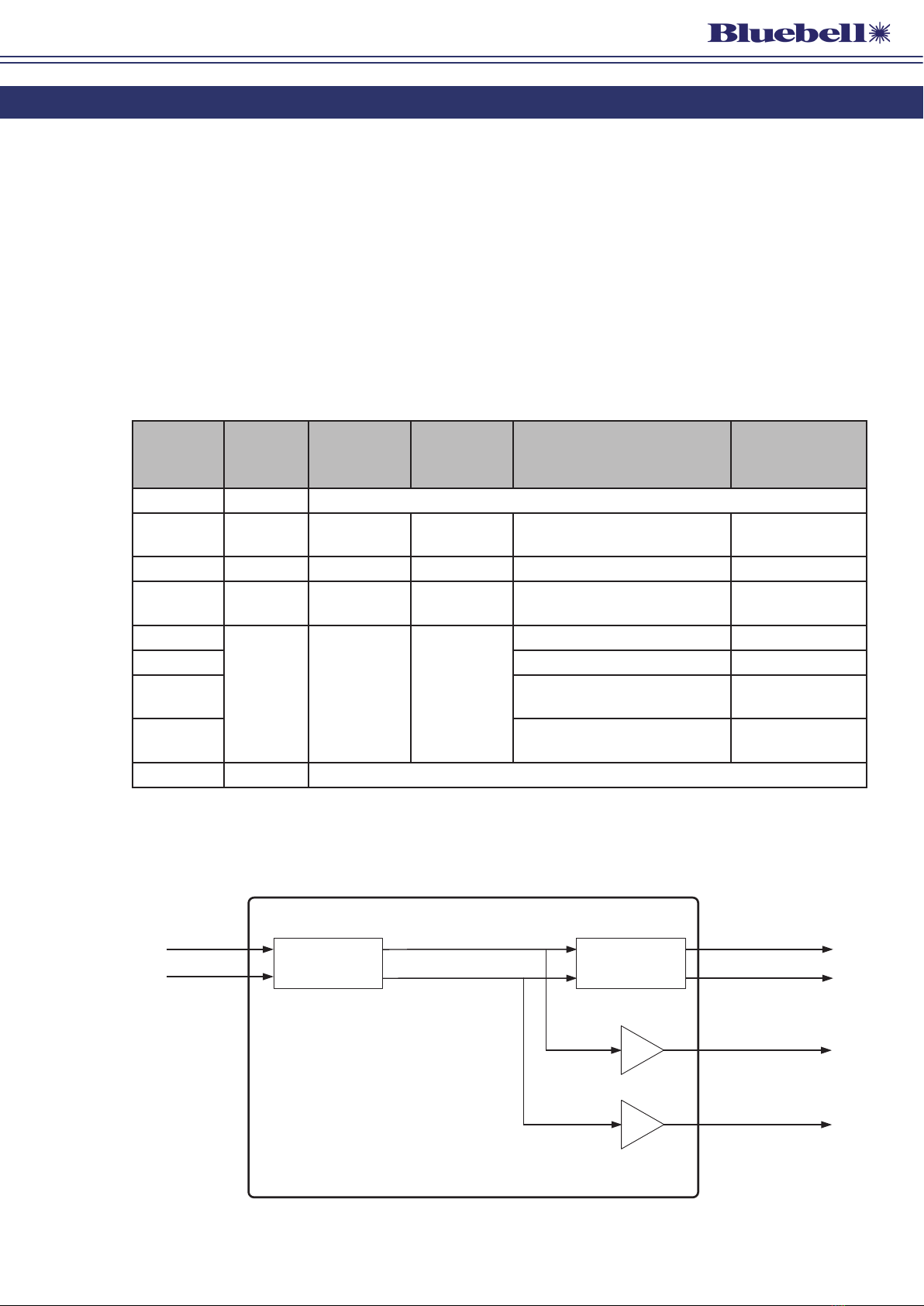
Configuration 1
Input Output
SFP 1 SFP 2
Cable Driver Serial Digital Output
HD-SDI 3 GB/s
Cable Driver
All Outputs are reclocked
Set the hex switch to ‘1’ to select this configuration.

BC364-OperationGuide-v1 9
This configuration will be useful for wavelength management when using multiple remote
cameras. Two BC364 modules can be allocated per two cameras, one module handling the
SDI feed from both cameras, the other the reverse video and control from the CCUs. Full
details on multi-camera use can be found in the BC364 Data and Applications Note, available
at www.bluebellcomms.co.uk/bc364-2.
Configuration 1 requires SFP 1 to be fitted with a dual receiver cartridge and SFP 2 with a dual
transmitter cartridge. The transmitter wavelengths should differ, allowing the use of a CWDM
optical multiplexer such as the Bluebell BC4.
Two separate signals are applied to the two optical ports of SFP 1; the two signal paths remain
independent within the module, and are transmitted via the two ports of SFP 2, typically at
different optical wavelengths from the input signals.
Both signals are reclocked, and either may be monitored locally via the BNC outputs (assuming
the signal being transported via fibre is of a suitable type, e.g, not RF modulated). Note that in
this configuration the upper BNC mirrors the signal transmitted from the upper port of SFP 2,
and the lower BNC mirrors that transmitted from the lower port of SFP 2, as shown below:
SFP 2
TOP
Configuration 1
SFP 1
Tx1
Rx2
Rx1
Tx2
BNC1
BNC2
(dual transmitter)
(dual receiver)
A
B
B
B
A
A
In Configuration 1, the status LEDs indicate signal lock as follows:
LED Green Red
LED A Valid lock at SFP 1 Rx2 Loss of lock* at SFP 1 Rx2
LED B Valid lock at SFP 1 Rx1 Loss of lock* at SFP 1 Rx1
* or reclocking disabled, or non-standard video bitrate
BC364-OperationGuide-v1 10
Configuration 2
Optical Input
and Ouput Output
SFP 2
Cable Driver Serial Digital Output
HD-SDI 3 GB/s
Cable Driver
All Outputs are reclocked
SFP 1
Set the hex switch to ‘2’ to select this configuration.
This configuration may be used as part of a fibre ring to provide local monitoring, and optionally,
additional HDMI or optical feeds for local distribution.
Configuration 2 requires SFP 1 to be fitted with a transceiver cartridge. The module is then
connected into the fibre ring, with the signal entering and leaving the transceiver at SFP 1 (the
lower port is the receiver input). Outputs for local monitoring are available at both BNC sockets
(assuming the signal being transported via fibre is of a suitable type, e.g., not RF modulated).
If required, an optical dual transmitter cartridge may be fitted to SFP 2. The outputs from this
will be the same at both ports, and will mirror the “copper” outputs at the BNCs. Alternatively,
an HDMI cartridge may be fitted in SFP 2, providing a local feed to monitors or other equipment
with an HDMI input.All outputs, including the re-transmitted input signal at SFP 1, are reclocked.
SFP 2
TOP
Configuration 2
SFP 1
Tx1
Tx
Rx
Tx2
BNC1
BNC2
(dual transmitter)
(transceiver)
A
B
B
B
A
A

BC364-OperationGuide-v1 11
In Configuration 2, the status LEDs indicate signal lock as follows:
LED Green Red
LED A Valid lock at SFP 1 Rx Loss of lock* at SFP 1 Rx
LED B Valid lock at SFP 1 Rx Loss of lock* at SFP 1 Rx
* or reclocking disabled, or non-standard video bitrate
Configuration 3
Optical Input
and Ouput
Cable Driver Serial Digital Output
HD-SDI 3 GB/s
Optical Input
and Ouput
Cable Driver
Serial Digital Output
HD-SDI 3 GB/s
All Outputs are reclocked
SFP 1 SFP 2
Set the hex switch to ‘3’ to select this configuration.
This configuration is useful when a duplex fibre ring is in use; the signal on either fibre may be
tapped into locally using the BNC outputs, either for monitoring or to feed other equipment.
Both SFP1 and SFP 2 should be fitted with transceiver cartridges. The signal at SFP 1‘s input
(the lower optical connector of the pair) will be reclocked and available at SFP 2’s output (the
upper optical connector of the pair) and the upper BNC connector. A second, symmetrical
signal path is available in the opposite direction, as the diagram on the following page shows:

BC364-OperationGuide-v1 12
SFP 2
TOP
Configuration 3
SFP 1
Tx
Tx
Rx
Rx
BNC1
BNC2
(transceiver)
(transceiver)
A
B
B
B
A
A
In Configuration 3, the status LEDs indicate signal lock as follows:
LED Green Red
LED A Valid lock at SFP 2 Rx Loss of lock* at SFP 2 Rx
LED B Valid lock at SFP 1 Rx Loss of lock* at SFP 1 Rx
* or reclocking disabled, or non-standard video bitrate
Configuration 4
Input Output
SFP 1 SFP 2
Cable Driver Serial Digital Output
HD-SDI 3 GB/s
Cable Driver
Control
All Outputs are reclocked
Set the hex switch to ‘4’, ‘5’, ‘6’ or ‘7’ to select this configuration. The differences between
these settings are discussed on the following page.

BC364-OperationGuide-v1 13
This configuration is intended to be used with a dual redundant fibre system. The module
accepts primary and secondary SDI signals, and makes one of them available at all outputs
for further distribution. SFP 1 is used for the two inputs, and both outputs of SFP2, and both
BNC outputs all carry the same signal.
SFP 1 is fitted with a dual receiver cartridge and SFP 2 with dual transmitter cartridge. The
method used to determine which of the two input signals is selected depends on the SET UP
switch setting, as follows:
Switch position 4: the selected source is Rx2. The signal at SFP 1 receiver 2 (the upper
optical connector of the pair) is permanently routed to all outputs. Signals at SFP 1 receiver
1 will be ignored.
Switch position 5: the selected source is Rx1. The signal at SFP 1 receiver 1 (the lower
optical connector of the pair) is permanently routed to all outputs. Signals at SFP 1 receiver
2 will be ignored.
Switch position 6: external source selection. Use of the signal at either SFP 1 receiver
1 or receiver 2 is determined by an external DC input, applied to the module through the
backplane connector. For applications requiring external control, please contact the
Bluebell Sales Office.
If multiple BC364 modules are present in the rack, all modules will switch their sources
simultaneously, a very useful fail-over provision.
Switch position 7: Automatic source selection. In this setting, selection of SFP 1 receiver
1 or receiver 2 is determined by optical signal strength. Default operation is with receiver
2; if the recovered signal level drops below a factory-set threshold, the module switches
automatically to the signal at receiver 1 – provided that this signal’s level is itself above the
threshold. If a usable signal level cannot be recovered from either receiver, receiver 2 is
selected as the default.

BC364-OperationGuide-v1 14
SFP 2
TOP
Configuration 4
SFP 1
Tx1
Rx2
Rx1
Tx2
BNC1
BNC2
(dual transmiter)
(dual receiver)
SWITCH
A
B
B
B
A
A
In Configuration 4, the status LEDs indicate signal lock as follows:
LED Green Red
LED A Valid lock at SFP 1 Rx1 or Rx2
(as selected)
Loss of lock* at SFP 1 Rx1 or Rx2
(as selected)
LED B Valid lock at SFP 1 Rx1 or Rx2
(as selected)
Loss of lock* at SFP 1 Rx1 or Rx2
(as selected)
* or reclocking disabled, or non-standard video bitrate
Auto mode
Auto mode should be selected by setting the SET UP switch to ‘0’. Switch positions ‘8’ to ‘F’
inclusive also select auto mode.
In auto mode, the BC364 module senses the type of SFP cartridge fitted in each carrier, and
configures the module as described in Configurations 1, 2 or 3 above. The following table
summarises the selections:
SFP 1 SFP 2 Configuration
Dual receiver Dual transmitter Configuration 1
Transceiver Dual transmitter Configuration 2
Transceiver Transceiver Configuration 3
It will be seen from the table at page 8 that both Configurations 1 and 4 require the same
pair of SFP cartridges: however,Auto mode will always select Configuration 1 for this cartridge
combination. Configuration 4 must be selected ‘manually’.

BC364-OperationGuide-v1 15
Operation with incorrect SFP cartridges
With Auto mode (hex switch position 0) or automatic source selection (hex switch position 7)
selected, the BC364 will default to the routing defined by hex switch position 4 if the cartridges
fitted do not match those required by any of Configurations 1, 2 or 3, or, if the SFPs are
unreadable. Thus in these cases, the upper optical connector of SFP 1 (receiver 2) will be the
active input, and the signal applied here will be available at all outputs.
Note that in hex switch positions 1 to 6 (inclusive) , the signal routing will be as described in
the section above (“The SET UP switch - BC364 operational configurations”) irrespective of
which SFP type are fitted.
Inadvertent operation with an incorrect SFP cartridge type will not damage the BC364 module.
SDI format compatibility
BC364 interfaces are intended for use with serial digital video (SDI) signals at data rates up
to 3 Gb/s. Standards supported are SD-SDI (SMPTE 259M-compliant at 270 Mb/s), HD-SDI
(SMPTE 292M-compliant at 1.483 and 1.485 Gb/s) and 3G-SDI (SMPTE 424M-compliant at
2.967 and 2.970 Gb/s). ASI baseband streams at 270 Mb/s are also compatible. Signals at
these standards will be detected and the relevant status LED(s) will illuminate green to indicate
“locked”. These signals can be re-clocked.
The BC364 will also pass signals at other bit rates, such as MADI at 125 Mb/s and other digital
video formats at 143 Mb/s, 177 Mb/s, 360 Mb/s, and 540 Mb/s, but in these cases, the status
LED(s) will illuminate red (“not locked”). These signals will not be re-clocked.

BC364-OperationGuide-v1 16
BC364 SFP combinations
TheBC364 isa format converter whosefunctionality andapplication will alwaysbe determined
by the type of cartridges fitted into the two SFP carriers. While the BC364 will generally be used
with fibre optic cartridges, several other types exist and are compatible with the module.
The table below illustrates some possible combinations of input and output formats. When
fitting non-optical cartridges, users should first consider the configuration in which the module
is to be used (i.e. the SET UP switch setting) as this will determine whether the two cartridges
will be single- or dual-channel, transmitters, receivers or transceivers. When this has been
decided, use the table to check that the combination of Input and Output SFPs is a compatible
one.
Optical
Transmitter
SM/MM
Optical
Receiver
SM/MM
Optical
Transmitter
SM 1550 nm
Optical
Transmitter
CWDM
Composite
Encoder
Composite
Decoder
3G/HD/SD-SDI/
ASI
Transmitter
3G/HD/SD-SDI/
ASI
Receiver
3G, HD-SDI,
SD-SDI, ASI,
MADI
3G, HD-SDI,
SD-SDI, ASI,
MADI
3G, HD-SDI,
SD-SDI, ASI,
MADI
3G, HD-SDI,
SD-SDI,
ASI only
3G, HD-SDI,
SD-SDI,
ASI
3G, HD-SDI,
SD-SDI
3G, HD-SDI,
SD-SDI
3G, HD-SDI,
SD-SDI
3G, HD-SDI,
SD-SDI
3G, HD-SDI,
SD-SDI
3G, HD-SDI,
SD-SDI
3G, HD-SDI,
SD-SDI
3G, HD-SDI,
SD-SDI
3G, HD-SDI,
SD-SDI
3G, HD-SDI,
SD-SDI
3G, HD-SDI,
SD-SDI
3G, HD-SDI,
SD-SDI
3G, HD-SDI,
SD-SDI,
ASI
3G, HD-SDI,
SD-SDI,
ASI
3G, HD-SDI,
SD-SDI,
ASI
3G, HD-SDI,
SD-SDI only
3G, HD-SDI,
SD-SDI only
3G, HD-SDI,
SD-SDI only
3G, HD-SDI,
SD-SDI only
SD-SDI only
SD-SDI only
SD-SDI only
SD-SDI only
SD-SDI SD-SDI SD-SDI SD-SDISD-SDISD-SDISD-SDI
MADI only
MADIMADIMADIMADI
HDMI
Decoder
DVI
Decoder
MADI
Decoder
HDMI 1.4
Encoder
DVI 1.0
Encoder
MADI
Encoder
INPUT
OUTPUT
The table cells at the intersections of inputs and outputs indicate the format of the “native”
internal signal. Both SFPs must be capable of handling the internal signal. Where the word
‘only’ is used, the output SFP can only accept a subset of the possible input signals.
Some of the non-optical SFP combinations shown above will clearly not be realisable with
certain of the BC364’s operational configurations, particularly where there is a conflict
between a configuration’s requirement for a transceiver SFP and the unidirectional nature
of some formats. Single channel SFPs may be used, but the user must check the signal flow
diagram for the intended configuration to see the effect of the missing channel. It should be
noted that as a general rule, single channel transmitters use port Tx1 and single channel
receivers use port Rx1.
In all cases, BC364 output signals are simply buffered and optionally re-clocked versions of
an input signal. The module does not convert any signal types but just re-generates them for
output, and will pass on any embedded audio that the SFPs can carry.
Please see also the tables of available cartridge types at page 21.

BC364-OperationGuide-v1 17
Other setup options
BC364 modules have five movable, internal PCB jumpers (“links”), LK1 to LK5, whose positions
modify the interface’s operation. There are no other user adjustments. The links are all set on
3-pin headers: a jumper is positioned either on pins 1 and 2 or 2 and 3 of the header.
LK1 and LK5 control the SDI signal reclocking in each of the module’s two output channels,
though their input source varies with the module’s operational configuration, as set on the
SET UP switch. Reclocking is enabled as the factory default. The following table defines the
signals in Output Channel A and Output Channel B for each configuration:
Output Channel A (ref LK1) Output Channel B (ref LK5)
Configuration 1 Input signal at SFP 1 Rx2 Input signal at SFP 1 Rx1
Configuration 2 Input signal at SFP 1 Rx Input signal at SFP 1 Rx
Configuration 3 Input signal at SFP 2 Rx Input signal at SFP 1 Rx
Configuration 4 Input signal at SFP 1 Rx1 or Rx2* Input signal at SFP 1 Rx1 or Rx2*
* In Configuration 4, the SFP 1 receiver in use is determined by the SET UP switch setting. LK1 controls
reclocking of the A outputs, and LK5 the B outputs. See the Configuration 4 block diagram at page 14.
LK2 and LK3 should be set according to whether either or both of the SFPs fitted are MSA (the
default setting) or non-MSA type.
LK4isforfactoryuseonly.Initsdefaultsetting,themodule’scontrolEEPROMiswrite-protected.
The table below summarises the jumper settings. Factory default settings are shown in
Bold
italics
.
Jumper Setting Issue 2 PCBs
LK1 Pins 1, 2 linked Ch A signal path reclocking disabled*
Pins 2, 3 linked
Ch A signal path reclocking enabled
LK2 Pins 1, 2 linked
When SFP 1 is data type (MSA)
Pins 2, 3 linked When SFP 1 is video type (non-MSA)
LK3 Pins 1, 2 linked
When SFP 2 is data type (MSA)
Pins 2, 3 linked When SFP 2 is video type (non-MSA)
LK4 Pins 1, 2 linked
(or no link) – EEPROM protected
Pins 2, 3 linked For factory use only
LK5 Pins 1, 2 linked Ch B signal path reclocking disabled*
Pins 2, 3 linked
Ch B signal path reclocking enabled
* When reclocking is disabled, the relevant status LED will permanently display red, indicating “not locked”.

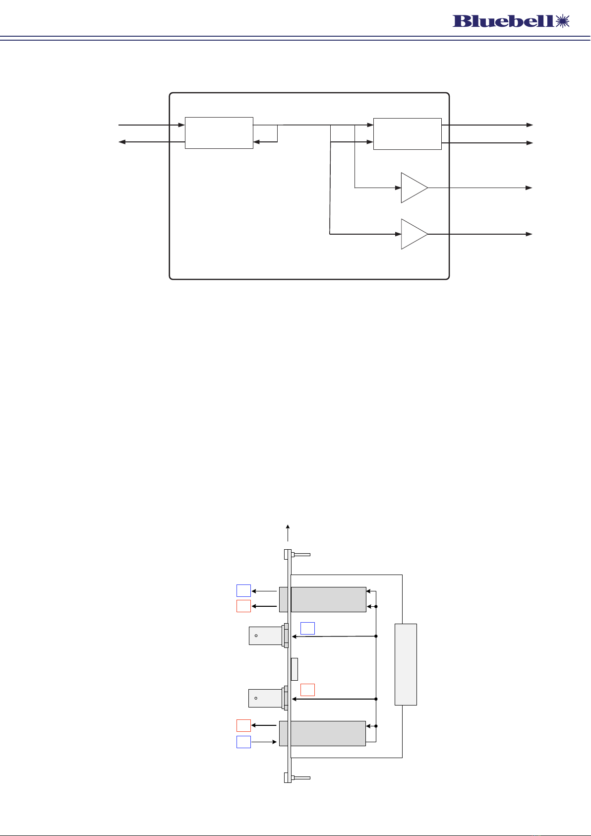
BC364-OperationGuide-v1 18
SFP 2
TOP
REAR
CONNECTOR
LK3
LK1
JUMPERS SHOWN IN ‘DEFAULT’
POSITIONS
SIMPLIFIED VIEW - ONLY PRIMARY
COMPONENTS SHOWN
LK2
BC364 – PCB layout
PIN 1
PIN 1
PIN 1
SFP 1
PIN 1
LK4
LK5
PIN 1
The diagram above shows the locations of the PCB jumpers. Note that on the PCB itself, Pin 1
of each jumper is indicated by a bevelled corner on the silkscreen outline around the header,
and a square solder pad on the rear of the module.

BC364-OperationGuide-v1 19
External monitoring
All modules in the Bluebell modular range can report their status to the rack in which they are
housed. The rack’s LEDs (two per module) will confirm correct operation (or otherwise), and if
the optional SNMP/Ethernet interface module is fitted, remote monitoring is available.
BC100/160 Frame Panel LEDs:
• Ch A: green = output channel A locked.
red = loss of lock of output channel A, or reclocking disabled, or non-standard
video bitrate.
red/green flashing = unable to read SFP 2.
• Ch B: green = output channel B locked.
red = loss of lock of output channel B, or reclocking disabled, or non-standard
video bitrate.
red/green flashing = unable to read SFP 1.
Monitoring via webpages:
“Overview” webpage:
• CH A LED: green = output channel A locked.
red = loss of lock of output channel A, or reclocking disabled, or non-standard
video bitrate.
red/green blinking = unable to read SFP 2.
• CH B LED: green = output channel B locked.
red = loss of lock of output channel B, or reclocking disabled, or non-standard
video bitrate.
red/green blinking = unable to read SFP 1.
“Frame Information” webpage:
SFP 1 is reported as “SFP 1”, SFP 2 is reported as “SFP 2”.
Monitoring via SNMP:
CH A Sig: good = equivalent to the Ch A Frame LED showing green
fail = equivalent to the Ch A Frame LED showing red
CH B Sig: good = equivalent to the Ch B Frame LED showing green
fail = equivalent to the Ch B Frame LED showing red
SFP 1 is reported as “sfp...”. SFP 2 is reported as “sfp2...”.
Note: if traps are enabled, a flashing LED will cause regular unwanted traps. This can be
avoided by setting the hex switch to one of the fixed modes (positions 1 through 6) or by
ensuring that valid SFPs are fitted to the card.

BC364-OperationGuide-v1 20
Appendix
Specifications – BC364
Monitoring Output
Connectors 2 x 75 ohm BNC per IEC 60169-8 Amendment 2
Standards supported* SMPTE 424M, SMPTE 292M, SMPTE 259M, SMPTE 297M, DVB-ASI
Return loss > 15 dB @ 1.485 Gb/s
DC Offset 0 ±0.5 V
Jitter <0.15 UI line equalised
Signal level 800 mV ±10%
Format Reclocked; may be bypassed via internal jumper
Other Output & Input
Physical SFP Module
Connector SFP Module dependent**
Signal detection Bicolour LED (green = lock, red = no lock/reclocking disabled/non-
standard video bitrate)
Conformities
EMI/RFI Complies with 89/336/EEC
Electrical Complies with EN 61000-6-1, EN61000-6-2
Laser Safety Class 1 laser safety compliant
RoHS Complies with Directive 2002/95/EC
Physical
Depth 86 mm (inc. connectors)
Width 20 mm (4HP)
Height 129 mm (3RU)
Weight 100 g
Operating Temp -30°C to +70°C
Power 3.7 W
* The “Standards supported” are those that can be reclocked and for which the status LEDs will give a “locked”
indication. Other non-standard signals are also permitted.
** Unit functionality is defined by the SFP modules fitted. See diagram at page 16 for currently available
combinations.
Table of contents
Other Bluebell Recording Equipment manuals


Popular Recording Equipment manuals by other brands


Louroe Electronics
Louroe Electronics AOP-XD Installation and operating instructions

Patton electronics
Patton electronics SmartNode 4650 datasheet

Axxess
Axxess GMOS-04 installation instructions

Schlage
Schlage WRI400 instructions

Masterflex
Masterflex E/S 07580-00 operating manual

Mitsubishi
Mitsubishi MAC-567IF-E installation manual