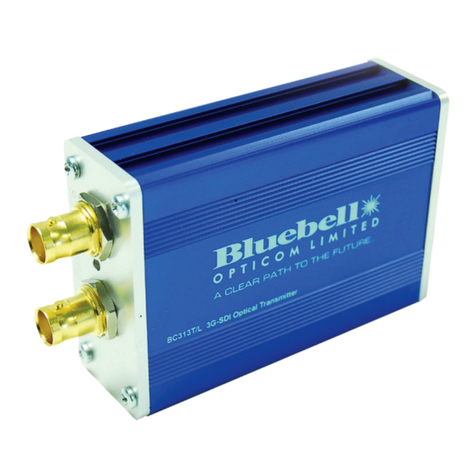
Bluebell BN328 Series User manual

BN328 Series Quad
12G Fibre Interfaces
Ref: BN328 QSG issue 1.0_08/22
Thank you for purchasing this Bluebell Opticom professional broadcast video product. BN328 interfaces
are very simple to install and this Quick Start Guide should provide sufcient information to get you up
and running in the vast majority of cases.
Quick Start Guide

BN328 Quick Start Guide V1.0
2
Overview:
The BN328 Series is a range of compact, stand-alone bre interfaces intended for remote video applications
of up to 8K format. They allow four independent SDI video signals meeting SD, HD, 3G, 6G or 12G
standards, plus one or two gigabit Ethernet data streams to be transported over a single bre-optic cable
for distances of up to 20 km*. They are ideal for use with remote 8K cameras employing quad 12G outputs
and Ethernet control, but can be used for any other application requiring transport of multiple SDI signals
and control data over long distances.
An optical “expansion” port allows a BN328 to be cascaded with a second, similar unit - or any other
optical source - operating on a different range of wavelengths to double the capacity of the single bre
link.
The “copper” connections are four BNC connectors for video and one or two RJ45 ports for Ethernet; the
optical port is a standard dual LC optical connector.
This Quick Start Guide covers the whole BN328 range, which comprises four models, each of which exists
in two variants. The rst four variants listed below operate using “High Band” optical wavelengths in the
range 1470 to 1610 nm:
• BN328T transmitter – quad SDI inputs plus Ethernet to an LC bre output
• BN328R receiver – LC bre input to quad SDI outputs plus Ethernet
• BN328TD transmitter – quad SDI inputs plus dual Ethernet to an LC bre output
• BN328RD receiver – LC bre input to quad SDI outputs plus dual Ethernet
The four additional variants below are functionally identical to those above, but use “Low Band” optical
wavelengths in the range 1270 to 1410 nm. A High Band unit and a Low Band unit can be cascaded using
the optical expansion port to double the signal capacity on the single bre length.
• BN328T-L transmitter – quad SDI inputs plus Ethernet to an LC bre output
• BN328R-L receiver – LC bre input to quad SDI outputs plus Ethernet
• BN328TD-L transmitter – quad SDI inputs plus dual Ethernet to an LC bre output
• BN328RD-L receiver – LC bre input to quad SDI outputs plus dual Ethernet
All variants are of identical construction, and in outward appearance differ only in the silk-screened
labelling:
In the following descriptions of usage, it can be assumed that the High Band and Low Band variant of the
same model are functionally identical, unless stated otherwise.
12V DC Input
Range: 8 - 17V DC
Optical I/O
LINK EXP
BN328R BN328RD
BN328TBN328TD
*Typical gure. Operational distance achievable in practice is dependent on bre type and number of intermediate connections

BN328 Quick Start Guide V1.0 3
Power supply:
All BN328 variants require an external power supply voltage between 5 and 17 V DC. A Bluebell Model
PS12 PSU (12 V) will be packed with the interface if one was ordered. The power supply connector is a
Neutrik® XLR4M, and a locking mating connector is pre-tted to the PS12 DC cable.
Inputs and outputs:
SDI Video:
BN328 interfaces can be used with serial digital video signals having data rates up to 12 Gb/s. Standards
supported are:
SD-SDI: SMPTE ST259M compliant
HD-SDI: SMPTE ST292M compliant
3G-SDI: SMPTE ST424M compliant
6G-SDI: SMPTE ST2081 compliant
12G-SDI: SMPTE ST2082 compliant
The interfaces are also compliant with SMPTE ST297, covering optical transmission of SDI video. DVB-ASI
baseband streams are also compatible.
Video inputs and outputs are on 75 ohm BNC sockets. All models have four connectors: inputs on the
BN328T/TD and outputs on the BN328R/RD. Each SDI connector has a bi-colour LED to conrm signal
lock.
Ethernet:
All BN328 models handle bidirectional Ethernet data via RJ45 connector(s) employing standard
Cat 5/Cat 6 network UTP cabling. Models with the sufx ‘D’ to their Part Number have a second RJ45
connector, and can cater for two independent Ethernet data streams.
The Ethernet ports are compatible with 10Base-T, 100Base-T and 1000Base-T data rates. Auto negotiation
is employed to select the correct data format, and full- or half-duplex operation without the need for any
manual conguration. The port is also compliant with MDI-X, allowing either “straight” or “crossed” cables
to be used, conguration being automatic.
Pin
1 0 V
2 n/c
3 n/c
4 +V DC
Model Power
BN328T
BN328T-L 7.5 W
BN328R
BN328R-L
BN328TD
BN328TD-L 9 W
BN328RD
BN328RD-L
If using an alternative PSU,
wire the connector as above.
BN328 range: typical power
consumption (measured with
4 x 12G SDI signals).

BN328 Quick Start Guide V1.0
4
Optical:
All BN328 models are tted with a dual LC optical connector. The two ports are marked LINK, and
EXP: LINK is the primary optical input or output, while the EXP port may be used for system expansion
purposes. (See Guide section “Using the BN328” for details.)
Optical operation is single-mode. Models BN328T use six wavelengths, Models BN328TD use eight, as
listed below:
Using the BN328:
Typically, BN328 units will be used in pairs, either with a BN328T/BN328R pair or a BN328TD/BN328RD
pair at the two ends of the bre run. For remote camera use, the transmitter interfaces (‘T’ models) will
be installed adjacent to the camera(s), and the receiver interfaces (‘R’ models) at the OB truck, MCR or
other base station.
Quad SDI and single Ethernet variants: BN328R and BN328T:
SDI 1
SDI 2
SDI 3
SDI 4
ETHERNET 1
(from CCU or
similar)
Video from camera;
control to/from camera
SINGLE FIBRE LINK
4 x SDI video
Ethernet
BN328R BN328T
BASE LOCATION REMOTE SITE
SDI 1
SDI 2
SDI 3
SDI 4
ETHERNET
(control)
Quad SDI and dual Ethernet variants: BN328RD and BN328TD:
SDI 1
SDI 2
SDI 3
SDI 4
ETHERNET 1
Video from camera;
control to/from camera(s)
SINGLE FIBRE LINK
4 x SDI video
2 x Ethernet
BN328RD BN328TD
BASE LOCATION REMOTE SITE
ETHERNET 2
SDI 1
SDI 2
SDI 3
SDI 4
ETHERNET 1
ETHERNET 2
Signal BN328T BN328TD BN328T-L BN328TD-L
Ethernet 2 1470 nm 1270 nm
Ethernet 2 1490 nm 1290 nm
Ethernet 1 1510 nm 1510 nm 1310 nm 1310 nm
Ethernet 1 1530 nm 1530 nm 1330 nm 1330 nm
SDI 1 1550 nm 1550 nm 1350 nm 1350 nm
SDI 2 1570 nm 1570 nm 1370 nm 1370 nm
SDI 3 1590 nm 1590 nm 1390 nm 1390 nm
SDI 4 1610 nm 1610 nm 1410 nm 1410 nm

BN328 Quick Start Guide V1.0 5
The interfaces in the previous diagrams could be either High Band or Low Band versions, provided the
same Band version is used at each end of the bre link.
In large OB situations where many remote cameras are employed, an alternative conguration might be to
replace the BN328R units at the base station with Bluebell BC Series modular interface cards in a BC100i
rack frame. This would be a tidier solution and would remove the multiplicity of “throw-down” units, each
with their SDI, Ethernet, bre-optic cables and PSUs.
SINGLE FIBRE LINK
MASTER
BC-8OPTICAL DEMULTIPLEXER
BC860
BC860
BC365R
BC365R
BC100i
RACK FRAME
Fibre patch cords
BN328TD
SDI 1
SDI 2
SDI 3
SDI 4
ETHERNET 1
ETHERNET 1
ETHERNET 2
SDI 1 / SDI 2
SDI 3 / SDI 4
ETHERNET 2
The example above illustrates a remotely-located BN328D connected to BC Series cards in a BC100i rack
frame in an MCR, OB truck or other base station via a single bre link. The optical data would be routed
via a BC-8 optical demultiplexer, which separates the signals using different wavelengths for onward
processing. The wavelengths carrying the SDI signals would be routed to two BC365R dual receiver cards
for recovery of the video; two BC860 cards would similarly recover the bidirectional Ethernet data.
This manual suits for next models
8
Table of contents
Other Bluebell Recording Equipment manuals
