Bluebell BlueLite User manual

BlueLite
Fibre video interface
Ref: BlueLite QSG issue 1.0_02/12/14
Thank you for purchasing this Bluebell Opticom professional broadcast video product. A
BlueLite fibre-optic link is simple to install and this Quick Start Guide should provide sufficient
information to get you up and running in the vast majority of cases.
Should you need additional information, an Operation Guide with full technical information is
available on request.
Quick Start Guide

BlueLite Quick Start Guide V1.0 2
Overview:
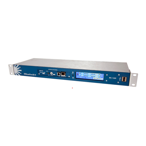
BlueLite interfaces are stand-alone fibre interface modules intended for OB use, typically to
provide the link between a truck or other base station and a remote camera position. The
interfaces allow simultaneous bidirectional transmission of two independent SDI video signals
and two independent audio signals, plus unidirectional transmission of composite video (i.e.,
genlock), RS-232/422 control data and two GPI tally lines.
A BlueLite link requires two modules, a Base unit (in the OB vehicle) and a Remote unit (at the
camera location). For this reason, BlueLite systems are normally supplied as a pair of units.
Within this Guide, SDI and audio signals originating at the Remote unit (camera end) are termed
sends
, while signals originating at the Base unit are termed
returns
.
Apartfromthedifferencesinpanelscreenprintresultingfrominput/outputconnectorallocation,
the two units are identical in appearance. Both end panels are clearly marked either “Base” or
“Remote”. The main connector panels of the two units are shown below:
Audio I/P 1 Audio I/O 2
Audio O/P 1
Data Output
Remote
3G-SDI
O/P 1
3G-SDI
O/P 2
3G-SDI
I/P 1
Loop
Composite
O/P
3G-SDI
I/P 2
Audio O/P 1 Audio I/O 2
Audio I/P 1
Data Input
Base
3G-SDI
I/P 1
3G-SDI
O/P 1
3G-SDI
I/P 2
Loop
Composite
I/P
3G-SDI
O/P 2
1
23
45
6
7
8
9
10
5
41
79
23
6
810

BlueLite Quick Start Guide V1.0 3
Camera end (Remote):
13G-SDI I/P 1 – connect the camera’s main SDI output here.
23G-SDI I/P 2 – this can be used for a second camera, or the second output from a 3D camera
for example.
3
Loop – an active loopthrough output of SDI I/P 2 for connection to other equipment.
43G-SDI O/P 1 – if needed, a return SDI feed from the base station is available at this
connector for monitoring or other purposes.
53G-SDI O/P 2 – as above.
6Composite O/P – this will normally be used for genlock; connect to the camera’s genlock
input.
7Audio I/P 1 –balanced input (XLR3F) for the audio Ch. 1 send to the base unit.
8Audio O/P 1 – balanced output (XLR3M) of the audio Ch. 1 return from the base unit.
9Audio I/O 2 – balanced input and output (XLR5F) of audio Ch. 2 send and return to/from the
base unit.
10 Data Output – if connected at the base end, RS-232/422 serial data will be present at this
D9F connector for camera control. Two GPI tally lines are also available for signalisation use.
Base end:
13G-SDI O/P 1 – the SDI signal from the camera.
23G-SDI O/P 2 – the second video signal connected to 3G-SDI I/P 2 at the camera end.
3Loop – a second (buffered) output of SDI O/P 2.
43G-SDI I/P 1 – connect a return SDI feed to the camera location here. This signal will be
available at the 3G-SDI O/P 1 connector at the remote unit.
53G-SDI I/P 2 – as [4] above; this signal will be available at the 3G-SDI O/P 2 connector at the
remote unit.
6Composite I/P – this will normally be used to feed genlock to the camera location.
7Audio O/P 1 – balanced output (XLR3M) of the audio signal connected to Audio I/P 1 at the
remote unit (audio send Ch. 1).
8Audio I/P 1 – balanced input (XLR3F) for connecting audio Ch.1 return feed to the remote unit.
9Audio I/O 2 - balanced input and output (XLR5F) of audio Ch. 2 return and send to/from the
remote unit.
10 Data Input – D9F connector for supplying RS-232/422 control data to the camera. Two GPI
tally lines are also available on this connector for base-to-camera signalisation.

BlueLite Quick Start Guide V1.0 4
Power supply:
Each BlueLite unit requires an external power supply of 12 V DC. The power supply connector
is a Neutrik® XLR4M; wire the mating connector as below:
The optional Bluebell Model PS12 PSU is ideal, as it is supplied pre-wired with a locking mating
connector.
The power consumption of a BlueLite module is 6.7 W.
Inputs and outputs:
Video:
The BlueLite system allows two independent 3G-SDI signals to be transported simultaneously
over fibre in each direction. The system is for use with serial digital video signals with data rates
up to 3 Gb/s. Standards supported are SD-SDI (SMPTE 259M-compliant), HD-SDI (SMPTE
292M-compliant) and 3G-SDI (SMPTE 424M-compliant).
All video inputs and outputs are on 75 ohm BNC sockets.
Audio:
The BlueLite system supports the simultaneous transport of two independent audio signals
(referred to as Audio Ch.1 and Audio Ch.2 in the Guide) in each direction. All audio inputs and
outputs are analogue, and electronically balanced on XLR connectors.
On both units, the inputs and outputs for Audio Ch.1 in each direction are on separate 3-pin
connectors; those for Audio Ch.2 are combined on a single 5-pin connector. The pinouts follow
the table below:
Pin Audio Ch.1 (XLR3) Audio Ch. 2 (XLR5)
All connectors Remote unit (F) Base unit (M)
1 Screen Screen Screen
2 ‘+’ (signal ‘hot’) Input ‘+’ (signal ‘hot’) Output ‘+’ (signal ‘hot’)
3 ‘-’ (signal ‘cold’) Input ‘-’ (signal ‘cold’) Output ‘-’ (signal ‘cold’)
4 Output ‘-’ (signal ‘cold’) Input ‘-’ (signal ‘cold’)
5 Output ‘+’ (signal ‘hot’) Input ‘+’ (signal ‘hot’)
Pin
10 V
2 n/c
3 n/c
4 +V DC

BlueLite Quick Start Guide V1.0 5
Data:
Camera control commands in RS-232 or RS-422 protocols may be sent over the fibre link
along with the return video and audio signals. Data transmission over a BlueLite link is
unidirectional, from the Base unit to Camera unit. The Data Input connector on the Base unit
should be connected to a serial output port on the Camera Control Unit (CCU) and the Data
Output connector on the Camera unit to the control input of the camera.
Note that the data link has the capacity for two RS-232 and two RS-422 controlled devices.
With suitably wired connectors, it is possible to control two individual devices at the camera
end, typically the camera itself and a separate PTZ mount.
The pinout of the D9F connectors is as follows:
Pin Camera unit Base unit
1 Logic 1 out Logic 1 in
2 Logic 2 out Logic 2 in
3 RS-232 #1 out RS-232 #1 in
4 RS-232 #2 out RS-232 #2 in
5 RS-422 #1 - out RS-422 #1 - in
6 RS-422 #1 + out RS-422 #1 + in
7 RS-422 #2 - out RS-422 #2 - in
8 RS-422 #2 + out RS-422 #2 + in
9 Ground Ground
The fibre link is transparent to serial port parameters, and the baud rate and other port settings
should be set on the CCU and camera as they would be for a direct connection.
The two GPI inputs on pins 1 and 2 may be used to control indicators at the camera location,
e.g., an “on-air” light.
The GPI inputs (and the corresponding outputs at the Camera end) use 3.3 V CMOS logic level
signals. Please consult the BlueLite Technical Manual if further information is required.
Optical:
A Neutrik® OpticalCOM DUO optical connector is fitted as standard; Lemo SMPTE Hybrid
connectors will be fitted instead if specified at the time of ordering. Standard fibre operation
is single-mode.

BlueLite Quick Start Guide V1.0 6
Using BlueLite:
BlueLite units should be used in pairs; a Remote unit and a Base unit. (An exception to this rule
is if a Bluebell BC Series modular rack system with suitable interface cards is installed at the
base station end.)
BlueLite
Camera end
3G-SDI RETURN 1
3G-SDI RETURN 2
3G-SDI INPUT 1
3G-SDI INPUT 2
LOOP OUT
COMPOSITE VIDEO
DATA A
DATA B
AUDIO RETURN 1
GPI 2
GPI 1
AUDIO RETURN 2
AUDIO INPUT 1
AUDIO INPUT 2
BlueLite
Base end
3G-SDI RETURN 1
3G-SDI RETURN 2
3G-SDI OUTPUT 1
3G-SDI OUTPUT 2
LOOP OUT
COMPOSITE VIDEO
DATA A
DATA B
AUDIO RETURN 1
GPI 2
GPI 1
AUDIO RETURN 2
AUDIO OUTPUT 1
AUDIO OUTPUT 2
1
7
1
2
3
4
5
6
7
8
9
9
10
5
4
1
7
9
9
2
3
6
8
10
LEDs:
On both types of module, bi-colour LEDs are fitted adjacent to each of the SDI BNC connectors.
These illuminate green to confirm a valid input signal, or red to indicate either no signal or
a signal which is in some way invalid. The LEDs adjacent to SDI output connectors indicate
whether a valid SDI signal has been recovered from the incoming fibre signal.
Reclocking:
The factory default is for the data at all the inputs (SDI or optical) to be internally reclocked.
This will generally be desirable for the majority of operational situations. The reclocking
circuitry may be bypassed on a per-channel basis by moving internal PCB jumpers; this may
be desirable when low data rates or asynchronous operation are in use. Please consult the
Operation Guide for details of how to do this.
SDI LED detection source:
Each SDI input and output (i.e., a total of four per unit) has an additional jumper that sets the
source signal for triggering the bi-colour LED. The default setting is for the LED to confirm a
valid SDI stream, but this may be altered to monitor the amplitude of the incoming signal, in
which case a red illumination indicates that the signal level is too low for data recovery to be
made.
Contact details:
Bluebell Opticom Ltd.
Unit 2, The Quadrant
Howarth Road
Maidenhead
Berkshire
SL6 1AP
United Kingdom
Tel: +44 (0) 1628 510055
Fax: +44 (0) 1628 510057
Email: [email protected]
Web: www.bluebell.tv
Table of contents
Other Bluebell Recording Equipment manuals
Popular Recording Equipment manuals by other brands

Gopel Electronic
Gopel Electronic PXI 3080 user manual

KONTRONIK
KONTRONIK PROGDISK manual
Sound Devices
Sound Devices 744T User guide and technical information

Shure
Shure PSM1000 Guía del usuario
Toshiba
Toshiba Surveillix EAV Series quick start guide

Warm Audio
Warm Audio WA76 discrete compressor Operation manual
