Bluebell BC363 User manual
Operation Guide
BC363
Multi-format interface
Ref: BC363-OperationGuide-v1
BC363
S/ L
OUTPUT INPUTOUTPUT

BC363-OperationGuide-v1 2
Bluebell Opticom Ltd.
Unit 2, The Quadrant
Howarth Road
Maidenhead
Berkshire
SL6 1AP
United Kingdom
Tel: +44 (0) 1628 510055
Fax: +44 (0) 1628 510057
Email: [email protected]
Web: www.bluebell.tv
Pleasenotethatalldocumentationhereinisofaconfidentialnatureandmaynotbereproduced
without written confirmation from Bluebell Opticom Ltd. The technical descriptions are to
aid service and repair only. Dissemination to a third party or parties will constitute breach of
copyright.
Information in this document is subject to change without notice and does not represent a
commitment on the part of Bluebell Opticom Ltd.
Bluebell Opticom Ltd. has taken all possible steps to ensure that the information given here
is both correct and complete. In no event can Bluebell Opticom Ltd. accept any liability or
responsibility for any loss or damage to the owner of the equipment, any third party, or any
equipment which may result from use of this manual or the equipment which it describes.
Declaration of Conformities
The components of the Bluebell Opticom BC363 Multi-format Interface complies with the
essential requirements of the following EU directives, where appropriate:
89/336/EEC, EN55022B, EN61000-4-2, EN61000-4-4 (Level 2), EN61000-4-4FTB,
EN61000-4-5, EN61000-4-11, EN61000-6-1, EN61000-6-2, EN61000-6-3, EN61000-6-4
Class 1 Laser Safety Compliant.
RoSH and WEEE declaration
Bluebell Opticom Ltd. complies with EU RoSH Directive 2002/95/EC, which restricts the use of
substances hazardous to humans and their environment in the manufacture of electrical and
electronic equipment.
The “crossed out wheelie bin” symbol on the enclosures and represented above is
there to remind users of the obligation of selective collection of waste. This label is
applied to various products to indicate that the product is not to be thrown away as
unsorted municipal waste. At the end of life, dispose of this product by returning it to the point
ofsale ortoyourlocal municipalcollection pointfor recycling ofelectric andelectronic devices.
Customer participation is important to minimize the potential effects on the environment and
humanhealth thatcan resultfrom hazardoussubstancesthat maybecontained inthis product.
Please dispose of this product and its packaging in accordance with local and national
disposal regulations, including those governing the recovery and recycling of waste electrical
and electronic equipment. Contact your local waste administration, waste collection company
or dealer.

BC363-OperationGuide-v1 3
Table of Contents
Declaration of Conformities ..........................................................................2
RoSH and WEEE declaration .........................................................................2
Overview ...................................................................................................... 4
Introduction..........................................................................................................................................4
Physical formats................................................................................................................................4
Power requirements ........................................................................................................................5
BC363 connections ......................................................................................6
System block diagram...................................................................................7
SDI format compatibility ................................................................................8
BC363 SFP combinations..............................................................................8
Configuration and setup options....................................................................9
External Monitoring .....................................................................................11
BC100/160 Frame Panel LEDs............................................................................11
Monitoring via webpages...........................................................................................................11
Monitoring via SNMP.....................................................................................................................11
Appendix ....................................................................................................12
Specifications – BC363.............................................................................................................12
SFP Options......................................................................................................................................13

BC363-OperationGuide-v1 4
Overview
Thank you for purchasing this Bluebell Opticom professional broadcast video product. If you
are new to Bluebell products, or to the subject of transmitting video and/or other types of signal
over fibre links, please take the time to read through this document before putting the BC363
to use.
Introduction
The BC363 plug-in card belongs to the range of the Bluebell Opticom BC Series modular fibre
interfaces, designed primarily for Outside Broadcast (OB) and studio applications. The card is
unidirectional, with input and primary output both in the form of SFP carriers. These will normally
be fitted with fibre-optic cartridges of the user’s choice, though compatible cartridges with
coaxial or other types of connector may be installed if wished. The card has a second output
in the form of a BNC socket.
The BC363 is intended for use with SDI video signals (3G-SDI, HD-SDI or SD-SDI), or with
ASI video signals, in situations where it is necessary to interface between two fibre-optic
systems using different fibre connectors. It can also be used as a “break-out” device, allowing
a 3G-SDI video signal to be “tapped-off” from a fibre link between two other locations.
If non-fibre optic cartridges are fitted into one of the I/O carriers, the card can act as a
fibre-to-copper converter with a local monitoring point.
Physical formats
BC363 cards fit the Bluebell BC100 or BC160 19” modular rack enclosures. The racks
can house fifteen (BC100) or six (BC160) interface cards, and are fitted with dual internal
AC power supplies.
Alternatively, cards may be fitted into smaller aluminium chassis; the BC101 and BC102
hold one and two cards respectively and require an external DC power source, while the
BC120 holds three cards and has an integral mains PSU.
BC363 cards are fitted with two SFP carriers. These will typically be fitted with dual fibre optic
cartridges, but copper interfaces may be fitted alternatively: connectivity options include
composite video, SDI, HDMI and DVI.
For fibre optic implementation, singlemode operation will normally be at 1310 nm or
1550 nm; alternative CWDM grid wavelengths are also possible. The optical option is generally
specified at the time of order.

BC363-OperationGuide-v1 5
Power requirements
Power supply requirements are dictated by the enclosure type used.
BC100 modular rack units:
These may be fitted with either one or two AC mains PSU modules (number specified at time of
order). Each module has sufficient capacity to power a fully-loaded rack.The AC connection is
via standard IEC cables, DC power distribution inside the rack is via the motherboard. See the
Operation Guide supplied with the rack units for more details.
BC160 modular rack units:
These are fitted as standard with dual internal AC mains power supplies, each of sufficient
capacity to power a fully-loaded rack. The AC connection is via standard IEC cables, DC
power distribution inside the rack is via the motherboard. See the Operation Guide supplied
with the rack units for more details.
BC101 and BC102 single- and dual-slot chassis:
These are supplied with an external Universal AC adaptor which connects to the chassis via a
flying lead terminated in a 4-pin locking XLR connector. Mains is via an IEC connector.
BC120 triple-slot chassis:
This housing for three plug-in cards is fitted with an internalAC mains supply; mains connection
is via a rear IEC connector.

BC363-OperationGuide-v1 6
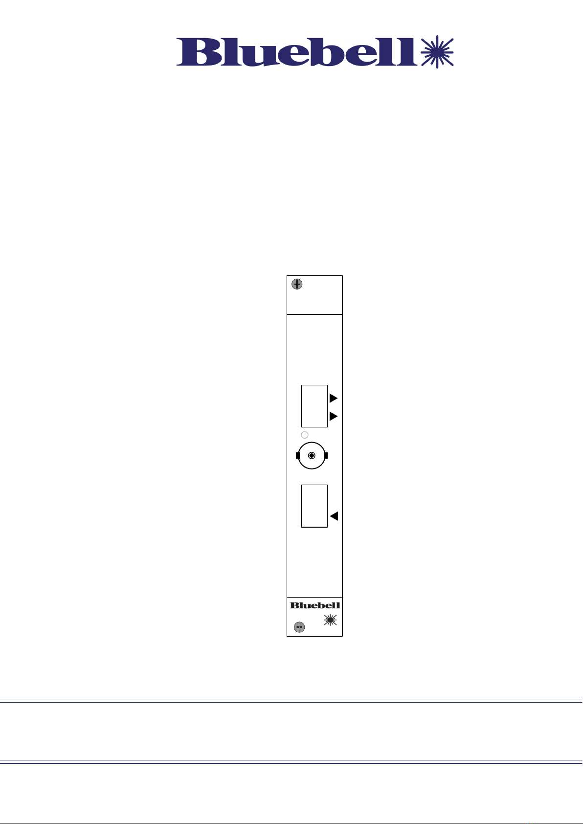
BC363 connections
BC363
S/ L
OUTPUT INPUTOUTPUT
1
2
4
3
Output SFP examples:
Singlemode dual channel video transmitter
Singlemode CWDM transmitter
Composite NTSC/PAL DIN
HDMI/DVI encoder
Input SFP examples:
Singlemode single channel video receiver
SDI coaxial receiver
HDMI/DVI decoder
Composite decoder
Example SFP
1. INPUT — SFP carrier for user’s choice of cartridge. When a dual fibre cartridge is fitted, the
input signal should be applied to the lower optical connector.
2. OUTPUT — SFP carrier for user’s choice of cartridge. When a dual fibre cartridge is fitted,
both optical connectors are active unless it is a transceiver, in which case only the upper
fibre port is active.
3. OUTPUT — standard 75 ohm BNC connector for SDI video, compliant with SMPTE
259/292/297/424 at data rates of between 270 Mb/s and 2.97 Gb/s. Also ASI-compatible.
4. S/L (‘signal loss’) — bi-colour LED; illuminates red to indicate loss of data lock and green to
indicate valid lock state.

BC363-OperationGuide-v1 7
System block diagram
BC363
SFP 1
Input
Input Output
Signal Detect on loss of signal
Serial Digital Output
Autosense
Reclocking
SFP 2
Output
Cable Driver
Factory default setting:
Reclocking on
The BC363 receives an incoming SDI or ASI signal at the INPUT SFP cartridge; this will
typically be via a single fibre-optic cable, but alternative SFP cartridges are available to allow
HDMI, DVI, etc., connectivity. After reclocking, the video signal is available for onward
distribution at both OUTPUT connectors. Again, an optical cartridge will typically be fitted in
the SFP carrier, though other connectivity options are available. The received and reclocked
signal is always available at the BNC connector.
BC363-OperationGuide-v1 8
SDI format compatibility
BC363 interfaces are intended for use with serial digital video (SDI) signals at data rates up
to 3 Gb/s. Standards supported are SD-SDI (SMPTE 259M-compliant at 270 Mb/s), HD-SDI
(SMPTE 292M-compliant at 1.483 and 1.485 Gb/s) and 3G-SDI (SMPTE 424M-compliant
at 2.967 and 2.970 Gb/s). ASI baseband streams at 270 Mb/s are also compatible.
Signals at these standards will be detected and the S/L LED will illuminate green to indicate
“locked”. These signals can be re-clocked.
The BC363 will also pass signals at other bit rates, such as MADI at 125 Mb/s and
other digital video formats at 143 Mb/s, 177 Mb/s, 360 Mb/s, and 540 Mb/s, but in these cases,
the S/L LED will illuminate red (“not locked”). These signals will not be re-clocked.
BC363 SFP combinations
Optical
Transmitter
SM/MM
Optical
Receiver
SM/MM
Optical
Transmitter
SM 1550 nm
Optical
Transmitter
CWDM
Composite
Encoder
Composite
Decoder
3G/HD/SD-SDI/
ASI
Transmitter
3G/HD/SD-SDI/
ASI
Receiver
3G, HD-SDI,
SD-SDI, ASI,
MADI
3G, HD-SDI,
SD-SDI, ASI,
MADI
3G, HD-SDI,
SD-SDI, ASI,
MADI
3G, HD-SDI,
SD-SDI,
ASI only
3G, HD-SDI,
SD-SDI,
ASI
3G, HD-SDI,
SD-SDI
3G, HD-SDI,
SD-SDI
3G, HD-SDI,
SD-SDI
3G, HD-SDI,
SD-SDI
3G, HD-SDI,
SD-SDI
3G, HD-SDI,
SD-SDI
3G, HD-SDI,
SD-SDI
3G, HD-SDI,
SD-SDI
3G, HD-SDI,
SD-SDI
3G, HD-SDI,
SD-SDI
3G, HD-SDI,
SD-SDI
3G, HD-SDI,
SD-SDI
3G, HD-SDI,
SD-SDI,
ASI
3G, HD-SDI,
SD-SDI,
ASI
3G, HD-SDI,
SD-SDI,
ASI
3G, HD-SDI,
SD-SDI only
3G, HD-SDI,
SD-SDI only
3G, HD-SDI,
SD-SDI only
3G, HD-SDI,
SD-SDI only
SD-SDI only
SD-SDI only
SD-SDI only
SD-SDI only
SD-SDI SD-SDI SD-SDI SD-SDISD-SDISD-SDISD-SDI
MADI only
MADIMADIMADIMADI
HDMI
Decoder
DVI
Decoder
MADI
Decoder
HDMI 1.4
Encoder
DVI 1.0
Encoder
MADI
Encoder
INPUT SFP1
OUTPUT SFP2
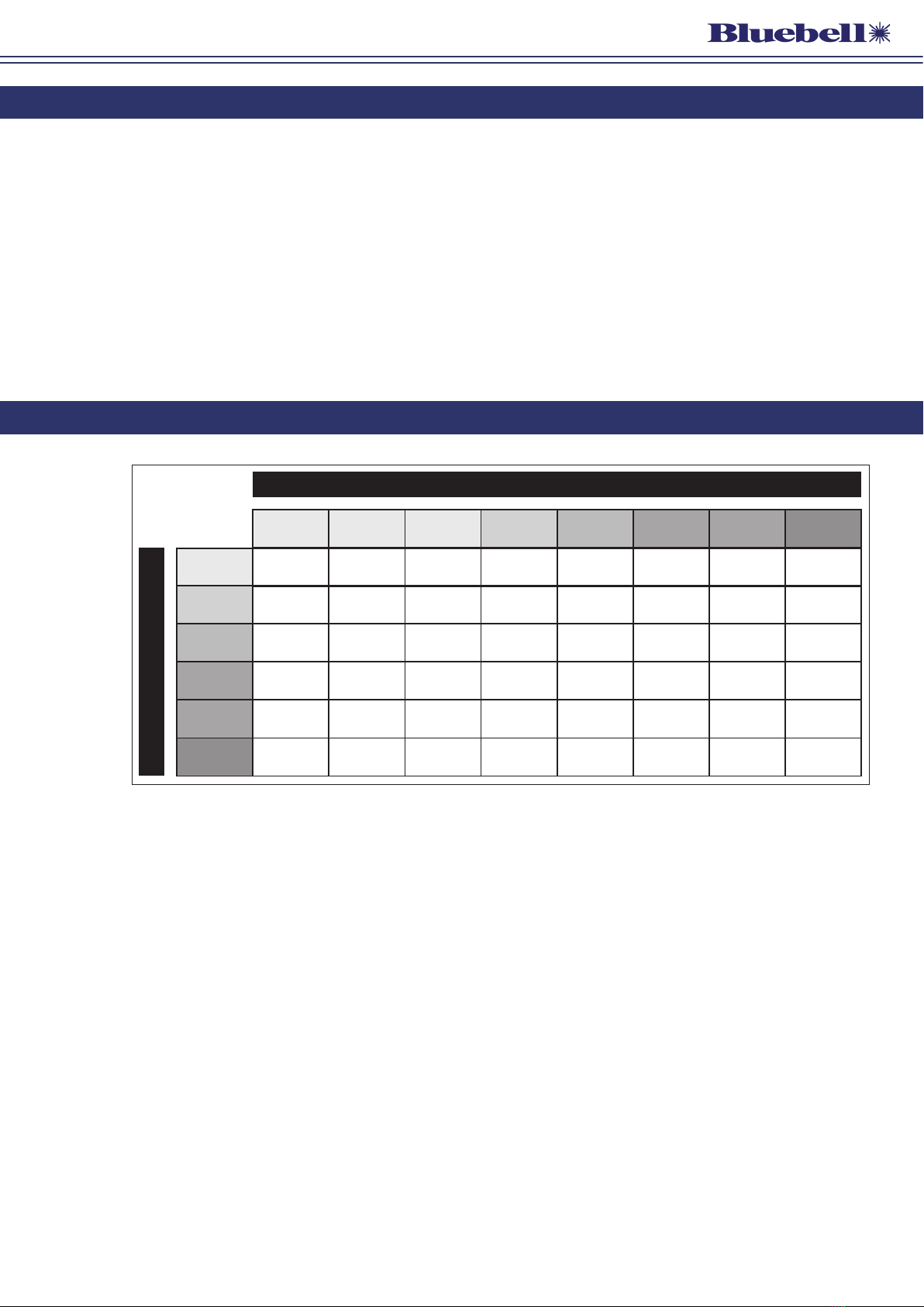
TheBC363 isa format converter whosefunctionality andapplication will alwaysbe determined
by the type of cartridges fitted into the INPUT and OUTPUT SFP carriers. The input signal will
always be available at the BNC OUTPUT connector regardless of the types of cartridge fitted.
The table above illustrates the possible combinations of input and output formats.
Cartridges supporting any of the formats listed vertically may be fitted to the INPUT SFP
carrier, and similarly, any of those listed horizontally to the OUTPUT carrier. The table
cells at the intersections of inputs and outputs indicate the format of the “native” internal
signal. Both SFPs must be capable of handling the internal signal. Where the word ‘only’ is
used, the OUTPUT SFP can only accept a subset of the possible INPUT SFP signals.
The signals sent to the OUTPUT SFP and OUTPUT BNC are simply buffered and optionally re-
clocked versions of the signal at the INPUT SFP. The card does not convert any signal types
but just re-generates them for the OUTPUT SFP, and will pass on any embedded audio that the
INPUT and OUTPUT SFPs can carry.
Please see also the tables of available cartridge types at “SFP Options” on page 13.

BC363-OperationGuide-v1 9
Configuration and setup options
BC363 cards have movable, internal PCB jumpers (“links”), whose positions modify the
interface’s operation. There are no other user adjustments.
There are two different versions of BC363 PCB: Issue 1 and Issue 2.
On Issue 1 cards, only one of the SFPs can be monitored at a time, and this selection is made
by the links LK2 and LK3. The SFP that is NOT to be monitored should not have a jumper fitted
to its associated link (LK2 for the INPUT SFP and LK3 for the OUTPUT SFP).
The SFP that is to be monitored should have a jumper fitted to its associated link, according to
the SFP type as indicated in the table below. If jumpers are fitted to both links (appropriate to
the type of SFP), then whether one or neither of the SFPs is reported correctly will depend on
the particular SFPs fitted. The default is that the input SFP will be monitored and so LK3 will
be set unlinked at the factory.
Issue 2 cards are able to read both SFPs separately, so both links LK2 and LK3 should have a
jumper fitted to select the type of SFP as indicated in the table below.
The table below summarises the jumper settings for both Issues of card. Factory default
settings are shown in Bold.
Jumper Setting Issue 1 PCBs Issue 2 PCBs
LK1 Pins 1, 2 linked Reclocking disabled* Reclocking disabled*
Pins 2, 3 linked Reclocking enabled Reclocking enabled
LK2
Pins 1, 2 linked When INPUT SFP is data type (MSA) When INPUT SFP is data type (MSA)
Pins 2, 3 linked When INPUT SFP is video type (non-MSA) When INPUT SFP is video type (non-
MSA)
No link fitted Disable INPUT SFP monitoring n/a
LK3
Pins 1, 2 linked When OUTPUT SFP is data type (MSA) When OUTPUT SFP is data type (MSA)
Pins 2, 3 linked When OUTPUT SFP is video type
(non-MSA)
When OUTPUT SFP is video type
(non-MSA)
No link fitted Disable OUTPUT SFP monitoring n/a
LK4 Pins 1, 2 linked (or no link) – EEPROM protected (or no link) – EEPROM protected
Pins 2, 3 linked For factory use only For factory use only
* When Reclocking is disabled, the S/L LED will permanently display red, indicating “not locked”.
BC363-OperationGuide-v1 10
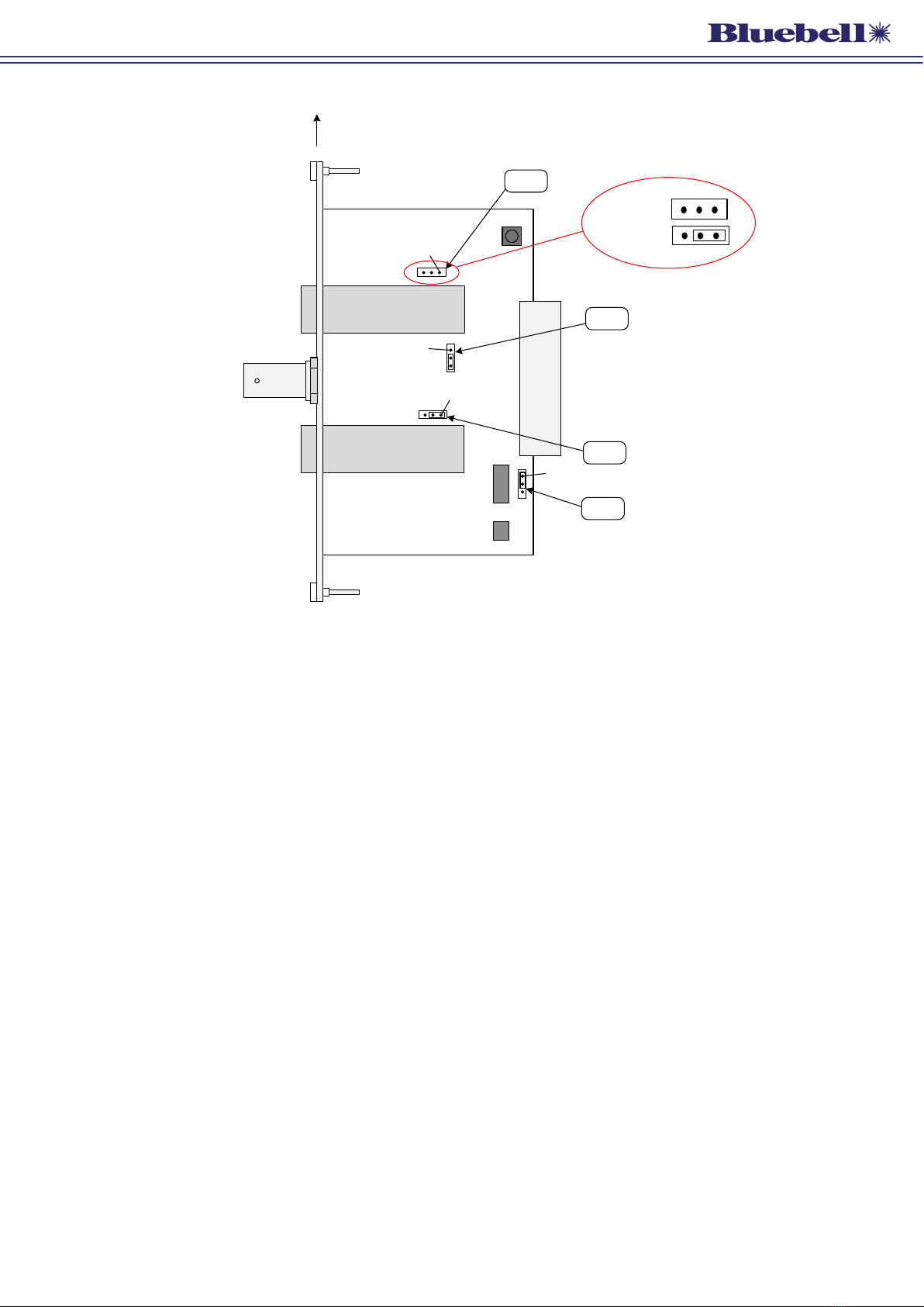
SFP
TOP
REAR
CONNECTOR
LK3
LK1
JUMPERS SHOWN IN ‘DEFAULT’
POSITIONS
SIMPLIFIED VIEW - ONLY PRIMARY
COMPONENTS SHOWN
LK2
BC363 – PCB layout
PIN 1
PIN 1
PIN 1
SFP
PIN 1
LK4
Issue 1 PCBs:
Issue 2 PCBs:
The diagrams above show the locations of the PCB jumpers. Note that on the PCB itself,
Pin 1 of each jumper is indicated by a bevelled corner on the silkscreen outline around the
header, and a square solder pad on the rear of the card.

BC363-OperationGuide-v1 11
External Monitoring
All modules in the Bluebell modular range can report their status to the rack in which they are
housed. The rack’s LEDs (two per module) will confirm correct operation (or otherwise), and if
the optional SNMP/Ethernet interface module is fitted, remote monitoring is available.
BC100/160 Frame Panel LEDs:
• Ch A: green = locked to signal at INPUT SFP connector
red = loss of lock of input signal, or locking disabled, or non-standard
video bitrate.
• Ch B: always off (no reporting on Ch B).
Monitoring via webpages:
“Overview” webpage:
• CH A LED: green = locked to signal from INPUT SFP
red = input signal not locked, or locking disabled, or non-standard video
bitrate.
• CH B LED: green = always (no errors reported on Ch B).
“
Frame Information
” webpage:
On cards with Issue 1 PCBs, the SFP selected by LK2 or LK3 is reported as “SFP 1”.
Nothing will be reported as “SFP 2”.
On cards with Issue 2 PCBs, the INPUT SFP is reported as “SFP 1”. The OUTPUT SFP
is reported as “SFP 2”.
Monitoring via SNMP:
• CH A Sig: good = locked to input signal.
fail = input signal not locked, or locking disabled, or non-standard video
bitrate.
• CH B Sig: good = always (no errors reported on Ch B).
On cards with Issue 1 PCBs, the SFP selected by LK2 or LK3 is reported as “sfp...”.
Nothing will be reported as “sfp2...”
On cards with Issue 2 PCBs, the INPUT SFP is reported as “sfp...”. The OUTPUT SFP is
reported as “sfp2...”.

BC363-OperationGuide-v1 12
Appendix
Specifications – BC363
Monitoring Output
Connector 1 x 75 ohm BNC per IEC 60169-8 Amendment 2
Standards supported* SMPTE 424M, SMPTE 292M, SMPTE 259M, SMPTE 297M, DVB-ASI
Return loss > 15 dB @ 1.485 Gb/s
DC Offset 0 ±0.5 V
Jitter <0.15 UI line equalised
Signal level 800 mV ±10%
Format Reclocked; may be bypassed via internal jumper
Other Output & Input
Physical SFP Module
Connector SFP Module dependent**
Signal detection Bicolour LED (green = lock, red = no lock)
Conformities
EMI/RFI Complies with 89/336/EEC
Electrical Complies with EN 61000-6-1, EN61000-6-2
Laser Safety Class 1 laser safety compliant
RoHS Complies with Directive 2002/95/EC
Physical
Depth 87 mm (inc. connectors)
Width 20 mm (4HP)
Height 129 mm (3RU)
Weight 100 g
Operating Temp -30°C to +70°C
Power 2.0 W
* The “Standards supported” are those that can be reclocked and for which the S/L LED will give a “locked”
indication. Other non-standard signals are also permitted.
** Unit functionality is defined by the SFP modules fitted. See diagram on page 8 for currently available
combinations.

BC363-OperationGuide-v1 13
SFP Options
The BC363’s functionality is entirely dependent on which type SFP cartridge is fitted to each of
the two carriers (INPUT and OUTPUT). Your BC363 card will be fitted with the SFP cartridges
that were specified at the time of ordering.
The tables below list some of the compatible SFP cartridges available at the time of printing;
others may become available over time. The application to which the BC363 may be put can
be changed at any time by fitting different cartridge in either or both the INPUT and OUTPUT
carriers. Please contact the Bluebell Sales Department with any specific requirements.
INPUT SFPs
SFP Part Ref. MSA? Description
Single/Dual Channel receivers:
VRS/S/SFP Non-MSA Singlemode single channel video wideband receiver
VR/S/SFP Non-MSA Singlemode dual channel video wideband receiver
VR/S/SFP/APD Non-MSA Singlemode dual channel video wideband APD receiver
Transceivers – standard wavelengths:
DTR/M/SFP MSA Multimode dual fibre transmitter 850 nm; wideband receiver
DTR/S/SFP MSA Singlemode dual fibre 40 km transmitter 1310 nm; wideband
receiver
SDI Coaxial DIN 1.0/2.3:
BB30CSRT-LN Non-MSA SDI Coaxial Transceiver, long reach, DIN
BB30CS2R-LN Non-MSA SDI Coaxial Dual Receiver, long reach, DIN
BB30CSRT-LNR Non-MSA SDI Coaxial Transceiver, long reach, reclocked, DIN
BB30CS2R-LNR Non-MSA SDI Coaxial Dual Receiver, long reach, reclocked, DIN
SDI Coaxial HD-BNC:
BB30HDRT-LN Non-MSA SDI Coaxial Transceiver, long reach, HD-BNC
BB30HDRT-LNR Non-MSA SDI Coaxial Transceiver, long reach, reclocked, HD-BNC
BB30HD2R-LNR Non-MSA SDI Coaxial Dual Receiver, long reach, reclocked, HD-BNC
Composite NTSC/PAL DIN:
BB30CSRT-AN Non-MSA COMPOSITE CODEC Coaxial Transceiver, DIN
BB30CS2R-AN Non-MSA COMPOSITE CODEC Coaxial Dual Receiver, DIN
Composite NTSC/PAL HD-BNC:
BB30HDRT-AN Non-MSA COMPOSITE CODEC Coaxial Transceiver, HD-BNC
BB30HD2R-AN Non-MSA COMPOSITE CODEC Coaxial Dual Receiver, HD-BNC
HDMI/DVI:
BB34TD1R-SN Non-MSA HDMI/DVI to SDI Receiver, Type D with retention clip
MADI:
BB06HD2R-MN-MADI Non-MSA MADI emSFPTM Coaxial Dual Receiver Medium reach, HD-BNC
BB06HDRT-MN-MADI Non-MSA MADI emSFPTM Coaxial Transceiver Medium reach, HD-BNC

BC363-OperationGuide-v1 14
OUTPUT SFPs
SFP Part Ref. MSA? Description
Single/Dual Channel transmitters – standard wavelengths:
VTS/S/SFP/13 Non-MSA Singlemode single channel video transmitter 1310 nm
VT/S/SFP/13/13 Non-MSA Singlemode dual channel video transmitter 1310/1310 nm
VT/S/SFP/13/15 Non-MSA Singlemode dual channel video transmitter 1310/1550 nm
VT/S/SFP/13/15/WDM Non-MSA Singlemode dual channel video single fibre transmitter
1310/1550 nm. Fitted with internal WDM MUX.
Dual channel transmitters – CWDM wavelengths:
VT/S/SFP/CWDM/27/29 Non-MSA Singlemode dual channel video CWDM transmitter 1270/1290 nm
VT/S/SFP/CWDM/31/33 Non-MSA Singlemode dual channel video CWDM transmitter 1310/1330 nm
VT/S/SFP/CWDM/35/37 Non-MSA Singlemode dual channel video CWDM transmitter 1350/1370 nm
VT/S/SFP/CWDM/39/41 Non-MSA Singlemode dual channel video CWDM transmitter 1390/1410 nm
VT/S/SFP/CWDM/47/49 Non-MSA Singlemode dual channel video CWDM transmitter 1470/1490 nm
VT/S/SFP/CWDM/51/53 Non-MSA Singlemode dual channel video CWDM transmitter 1510/1530 nm
VT/S/SFP/CWDM/55/57 Non-MSA Singlemode dual channel video CWDM transmitter 1550/1570 nm
VT/S/SFP/CWDM/59/61 Non-MSA Singlemode dual channel video CWDM transmitter 1590/1610 nm
Transceivers – standard wavelengths:
DTR/M/SFP MSA Multimode dual fibre transmitter 850 nm; wideband receiver
DTR/S/SFP MSA Singlemode dual fibre 40 km transmitter 1310 nm;
wideband receiver
Transceivers – CWDM wavelengths:
DTR/S/SFP/CWDM/27 MSA Singlemode CWDM transmitter 1270 nm; wideband receiver
DTR/S/SFP/CWDM/29 MSA Singlemode CWDM transmitter 1290 nm; wideband receiver
DTR/S/SFP/CWDM/31 MSA Singlemode CWDM transmitter 1310 nm; wideband receiver
DTR/S/SFP/CWDM/33 MSA Singlemode CWDM transmitter 1330 nm; wideband receiver
DTR/S/SFP/CWDM/35 MSA Singlemode CWDM transmitter 1350 nm; wideband receiver
DTR/S/SFP/CWDM/37 MSA Singlemode CWDM transmitter 1370 nm; wideband receiver
DTR/S/SFP/CWDM/39 MSA Singlemode CWDM transmitter 1390 nm; wideband receiver
DTR/S/SFP/CWDM/41 MSA Singlemode CWDM transmitter 1410 nm; wideband receiver
DTR/S/SFP/CWDM/47 MSA Singlemode CWDM transmitter 1470 nm; wideband receiver
DTR/S/SFP/CWDM/49 MSA Singlemode CWDM transmitter 1490 nm; wideband receiver
DTR/S/SFP/CWDM/51 MSA Singlemode CWDM transmitter 1510 nm; wideband receiver
DTR/S/SFP/CWDM/53 MSA Singlemode CWDM transmitter 1530 nm; wideband receiver
DTR/S/SFP/CWDM/55 MSA Singlemode CWDM transmitter 1550 nm; wideband receiver
DTR/S/SFP/CWDM/57 MSA Singlemode CWDM transmitter 1570 nm; wideband receiver
DTR/S/SFP/CWDM/59 MSA Singlemode CWDM transmitter 1590 nm; wideband receiver
DTR/S/SFP/CWDM/61 MSA Singlemode CWDM transmitter 1610 nm; wideband receiver
SDI coaxial DIN 1.0/2.3:
BB30CS2T-LN Non-MSA SDI Coaxial Dual Transmitter, long reach, DIN
BB30CSRT-LN Non-MSA SDI Coaxial Transceiver, long reach, DIN
BB30CS2T-LNR Non-MSA SDI Coaxial Dual Transmitter, long reach, reclocked, DIN
BB30CSRT-LNR Non-MSA SDI Coaxial Transceiver, long reach, reclocked, DIN

BC363-OperationGuide-v1 15
OUTPUT SFPs
SFP Part Ref. MSA? Description
SDI coaxial HD-BNC:
BB30HD2T-LN Non-MSA SDI Coaxial Dual Transmitter, long reach, HD-BNC
BB30HDRT-LN Non-MSA SDI Coaxial Transceiver, long reach, HD-BNC
BB30CS2T-LNR Non-MSA SDI Coaxial Dual Transmitter, long reach, reclocked, HD-BNC
BB30CSRT-LNR Non-MSA SDI Coaxial Transceiver, long reach, reclocked, HD-BNC
Composite NTSC/PAL DIN:
BB30CS2T-AN Non-MSA COMPOSITE CODEC Coaxial Dual Transmitter, DIN
BB30CSRT-AN Non-MSA COMPOSITE CODEC Coaxial Transceiver, DIN
Composite NTSC/PAL HD-BNC:
BB30HD2T-AN Non-MSA COMPOSITE CODEC Coaxial Dual Transmitter, HD-BNC
BB30HDRT-AN Non-MSA COMPOSITE CODEC Coaxial Transceiver, HD-BNC
HDMI/DVI:
BB34TD1T-SN Non-MSA SDI to HDMI/DVI Transmitter, Type D with retention clip
MADI:
BB06HD2T-MN-MADI Non-MSA MADI emSFPTM Coaxial Dual Transmitter, medium reach,
HD-BNC
BB06HDRT-MN-MADI Non-MSA MADI emSFPTM Coaxial Transceiver, medium reach, HD-BNC
NOTE: When a transceiver cartridge is fitted to the OUTPUT SFP carrier, only one transmission channel is
available: this will always be the upper port of the pair.
Table of contents
Other Bluebell Recording Equipment manuals


Popular Recording Equipment manuals by other brands

TRIVIEW
TRIVIEW TDR-3604R Installation and operation manual

Cressi
Cressi CARTESIO NEON GOA Guide

Monacor
Monacor PA-24FR instruction manual

Bosch
Bosch D8125MUX Installation and operation guide

Kawai
Kawai Standard MIDI Files Compatible Sequencer... Operation guide

TC Electronic
TC Electronic NOVA System user manual


