bluefin Master Vision THBF805 User manual


Installation Manual
Description
0
8
13- 22
Power pe
b
b
,
x
F

Installation Manual
Specications
°°°°
°°°°
° °
° °
°°°
°

Installation Tips
9
•
N
ear hot or cold air ducts
• In direct sunlight
•
O
n an outside ad
j
acent
wall
• In areas that do not
require conditioning
•
N
ear dead spots or drafts
(in corners or behind doors)
•
N
ear concealed chimneys
or pipes

Subbase Installation
®
@�
/
/
,
,
Installation Tips
•Installation Tip:
= Electrical Hazard
•Mercury Notice
-
e

4
Sun 8.nn�M
·UU WAKE

Installation Tips
Battery Installation
�
@
Important:
I �
L
/
'
0

Installation Tips
About The Badge
+

1.sv AAA0 ! � lSV AAA
&'
t·fr
8 •
111111111111111111
At
° O -
,
0
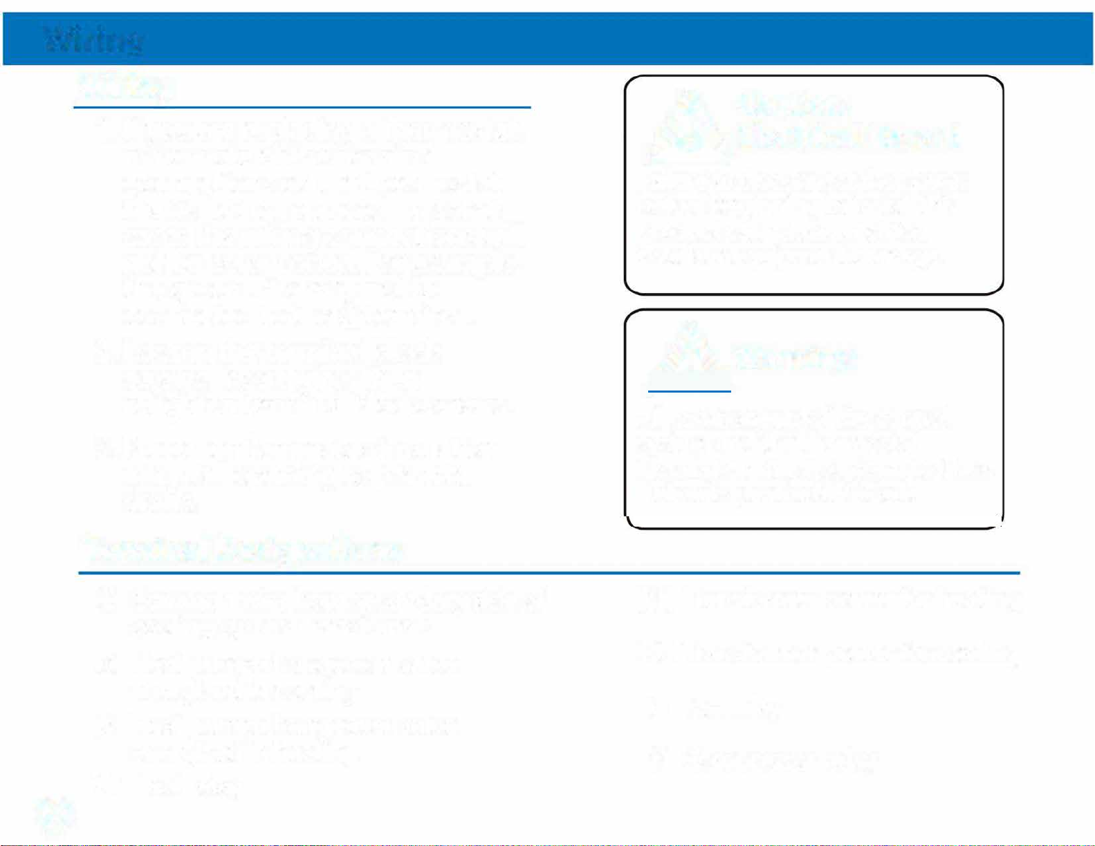
Wiring
0
Wiring
Terminal Designations
A Caution:
� Electrical Hazard
A
warning:
C RH
0
B
RC
Y

Wiring Tips
RH & RC Terminals
H P S (With NO AUX or
eat ump ystems Emergency Heat)
Wiring
CTerminal
Wire Specications
Installation Tip:
Max Torque = 6in-lbs.
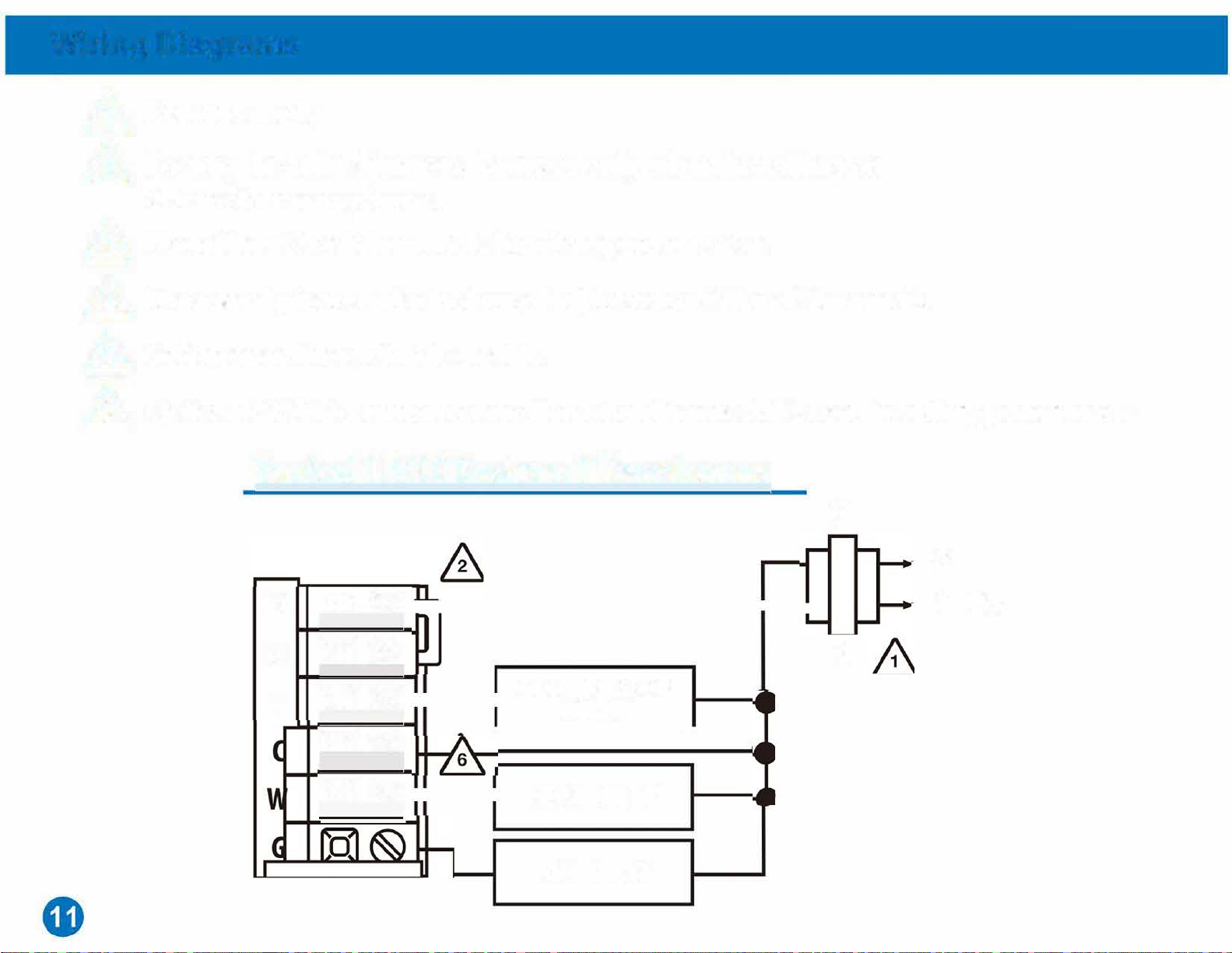
Wiring Diagrams
RC
-----
RH @
V
COMPRESSOR
RELAY
HEAT REL
FAN RELAY
C
L2
L1 HOT
R
-
RC
RH
V
C
G
Typil 1 H/1 C Heat Pump System &
C
& �L2
�L1 HOT
&
R
�
&6
Wiring Diagrams
0
B

Technician Setup
1. Press MENU button
2. Press and hold TECHNICIAN SETUP button for 3 seconds. This 3 second delay is
designed so that homeowners do not accidentally access the installer settings.
3. Congure the installer options as desired using the table below.
4. Use the or keys to change settings and the NEXT STEP or PREV
STEP key to move from one step to another. Note: Only press DONE key when you
want to exit the Technician Setup options.
Tech Setup Steps LCD Will Show Adjustment Options Default
1
I� I�
Room
Temperature
Calibration
°
°
°
OFF
0

Technician Setup
u,-
[□MP PROTECTS
nn
u,'
S�JING
0[
-
U.�
I I • I I
OFF
ON
0.5
e

Technician Setup
Tech Setup Steps LCD Will Show Adjustment Options Default
n,_. o[
U. I
,,o[
,.�
°
°
°
°
°
°
0.4
32°

Technician Setup
12 or 24
Hour Clock
F R SET °
,
□
0[°
.- oc
: 2 H
HOUR [OD< SETTING 12 Hour
Clock

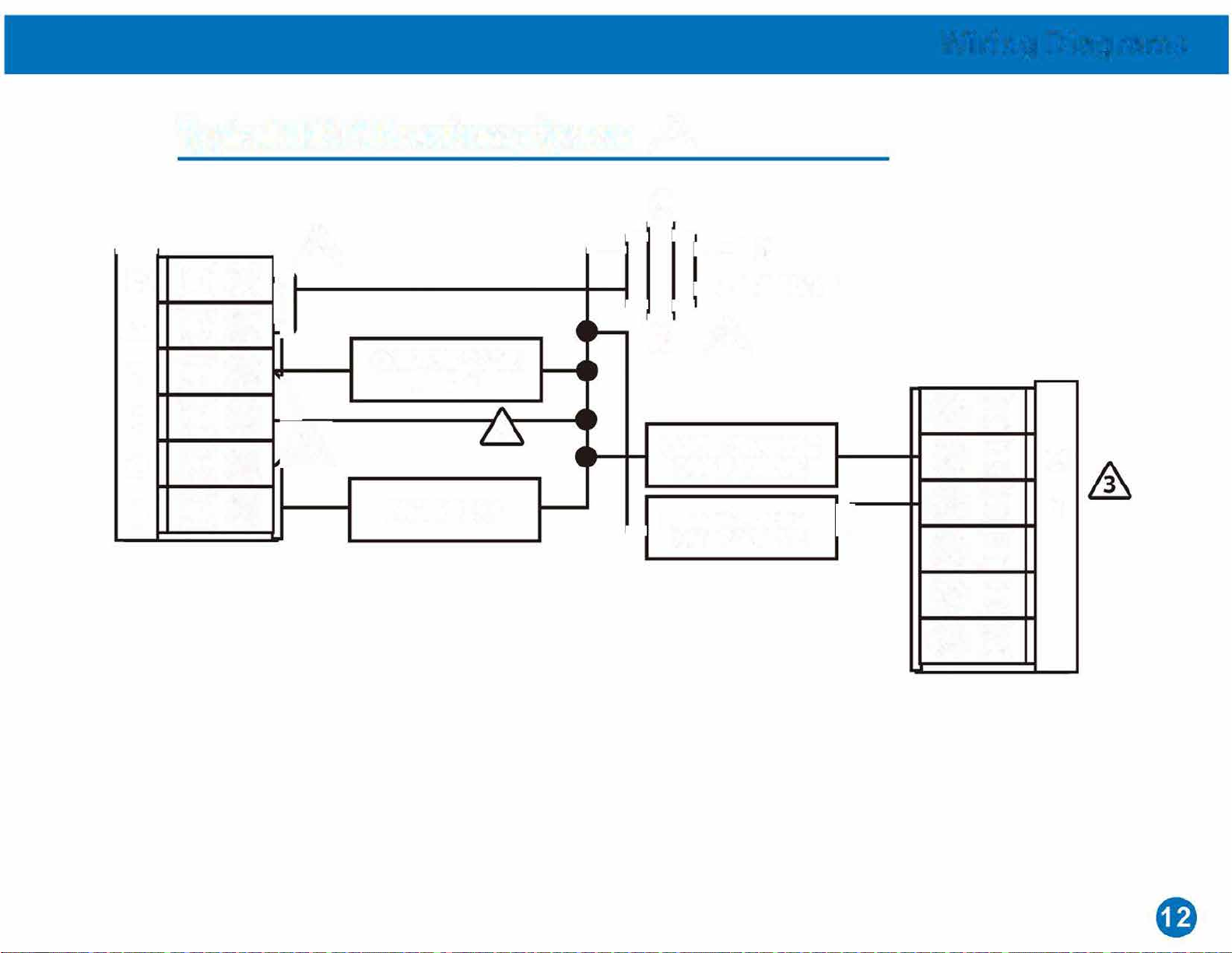
Wiring Diagrams
C
RC
RH
V
C 6
w
G
REMOVE JUMPER C
� L2
RC
RH R 1
V
C
�·
w
�-
G
C
R

y
W HEAT RELAY
G
C
L2
L1 HOT
R&
Wiring Diagrams
C
L2
_
Ll HOT
R
y � COMPRESSOR
� RELAY
FAN RELAY

Technician Setup
Tech Setup Steps LCD Will Show Adjustment Options Default
Fan
Operation
Morning
Recovery
Program
Options
□
nn
u,'
□
GAS
ON
5d
Table of contents
Other bluefin Thermostat manuals


Popular Thermostat manuals by other brands


MMA
MMA Evosense sprint Series Installation instruction

DEVI
DEVI devireg 316 installation instructions

Braeburn
Braeburn Builder 2200 user manual

Venstar
Venstar ColorTouch T6800 Owner's manual and installation instructions

Onyx Controls
Onyx Controls ONX908PIT-V1-S1-F3/B Installation and operation instruction manual

Honeywell
Honeywell Digital Round T8775A Product data


