Declaration
EP600 ESS (Energy Storage System) overview
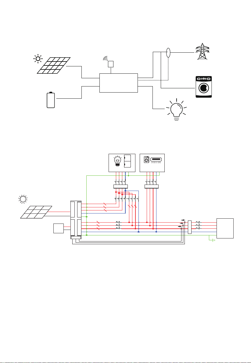
DC coupling
AC coupling
AC-DC coupling
Stacking EP600 ESS
Place the base firmly on the ground
Move units onto the base
Attach the mounting brackets
Electrical connections
Connect the grounding cables
Connect the GRID and BACKUP cables
Install the AC cable protection case
Connect the CT signal cable
Connect the battery power cables
Connect the communication cables between EP600 (LINK
PORT2) and B500 (TO PCS)
Connect the battery expansion cables between B500s
Install the IoT controller
Connect the PV cables
Attach the plastic covers to EP600
Connect to the main panel
Power on the ESS
BLUETTI App control
Introduction
Firmware upgrade
More information
Contents
1
2
2.1
2.2
2.3
3
3.1
3.2
3.3
4
4.1
4.2
4.3
4.4
4.5
4.6
4.7
4.8
4.9
4.10
4.11
5
6
6.1
6.2
7
04
04
05
06
07
08
08
08
08
10
10
10
12
12
13
15
16
17
18
19
19
26
26
26
27
27