Bluetti EP500 User manual

EP500 POWER STATION
Please read this manual before use and follow its guidance. Keep this manual for future reference.

User Manual
Please read this manual before use and follow its guidance. Keep this manual for future reference.

Contents/Inhalt
Deutsch.....................................................43-84
01. Einführung in EP500 .............................. 43
02. Allgemeine Sicherheitshinweisen .....
............................................................................................ 44
03. Was ist im Lieferumfang? ................. 48
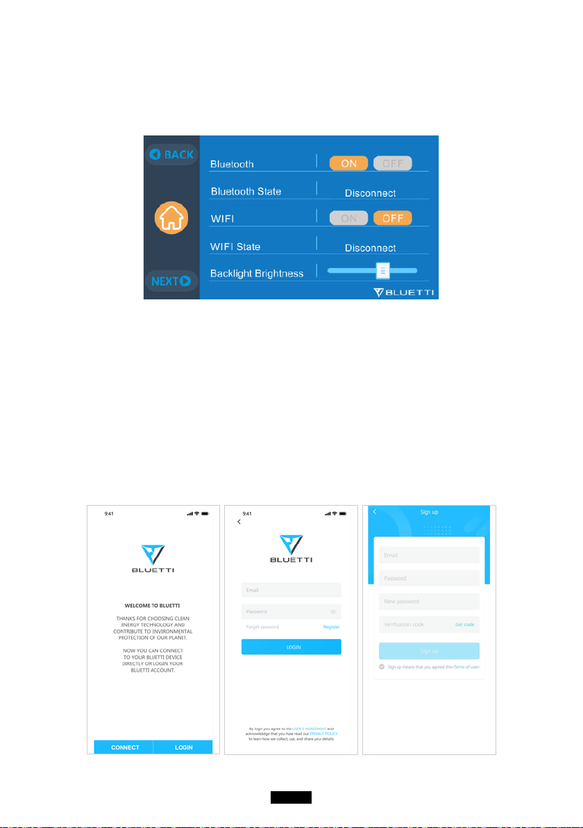
04. APP-Benutzerhandbuch .................. 49
05. Eigenschaften der EP500.....................53
06. Ein- &Ausschalten ......................................54
07. Benutzeroberfläche.................................. 55
08. Wie laden sie die EP500 auf
(Eingang).....................................................................62
09. Entladen (Ausgang) ............................... 66
10. UPS ......................................................................... 69
11. Split-Phase Funktion .................................74
12. Technische Spezifikation ..................... 76
13. Lagerung und Wartung ....................... 78
14. Fehlerbehebung ........................................ 78
15. FAQ (Häufig gestellte Fragen) ........ 83
16. Erklärung ............................................................84
English....................................................... 01-40
01. EP500 Introduction ................................... 01
02. General Safety Instructions .............. 02
03. What`s in the Box .................................... 06
04. APP User Guide ......................................... 07
05. Features of the EP50................................. 11
06. Start up & Power off ...................................12
07. User Interface ................................................. 13
08. How to charge the EP500 (INPUT) ...
.............................................................................................20
09. Discharge (OUTPUT) .............................. 24
10. UPS ......................................................................... 27
11. Split Phase Function .................................. 31
12. Technical Specification .......................... 33
13. Storage and Maintenance .................. 35
14. Troubleshooting .......................................... 35
15. FAQ (Frequently Asked Questions) ....
............................................................................................ 38
16. Declaration ...................................................... 40

EN-01
Just Power On
01. EP500 Introduction
1.1. Introduction
• BLUETTI is proud to take the energy storage world by storm with the release
of its first home energy storage system series - the EP500. With four smooth-
rolling transport wheels, the EP500 was not designed to be a large solar
battery mounted on the wall or in the garage. The BLUETTI EP500 was not only
designed to be a "No Installation Needed", plug-and-play mobile UPS that can
easily be moved to a desired location when necessary. But also a power backup
system that ensures available emergency power when power outages occurs.
• The EP500 system uses a dual-core controller (ARM controller + DSP controller)
which combines digital and analog signals perfectly to manage and control the
AC Charger module, the MPPT module, the AC Inverter module, the DC-to-DC
module, and the Battery module.
• This product integrates a solar charge controller, AC charge controller, AC
inverter, lithium battery and battery management system into one. It converts
clean and environmentally friendly solar energy and grid electricity into clean
electricity and sends it to all of your connected loads in your home.
• The EP500 Power Station system is suitable for areas with energy shortages or
unstable power. And also supplies power to disaster emergency areas without
electricity such as isolated islands and border posts.
( EP500 grid-tie home
power back up system )

EN-02
BLUETTI
1.2. Abbreviation
• BMS: Battery Management System
• MPPT: Maximum Power Point Tracking
• UPS: Uninterruptible Power Supply
• AC: Alternating Current
• DC: Direct Current
• PV: Solar Panel(s) Charging (Photovoltaic)
• Grid: Home Power Supplied by Utility
• T500: 500W Additional Adapter
• DOD: Depth of Discharge
• ECO Mode: A power saving mode for the EP500. In this mode, the AC output
ports are automatically turned off if the load is less than 20W over a span of 4
hours.
02. General Safety Instructions
Please read this manual before operating.
• A licensed electrician is required to install the grid-tied power system as it
involves connecting the wires of critical loads from your main electrical box to
the BLUETTI Sub Panel (Optional Purchase).
• DO NOT place the power station near heat sources. It is prohibited to place the
equipment in an environment with flammable, explosive gas, or smoke. It is also
prohibited to operate the equipment in this environment.
• DO NOT attempt to replace the internal battery or any other component of the
equipment by anyone other than authorized personnel. There are no enduser
serviceable components.
• DO NOT operate in wet conditions. If the equipment becomes wet, please let the
unit dry completely before using.
• Please ensure proper ventilation while in use and do not obstruct fan openings.
Inadequate ventilation may cause permanent damage to the equipment.
• DO NOT stack anything on top of the power station while in storage or while in
use. DO NOT move the unit while operating as vibrations and sudden impacts

EN-03
Just Power On
may lead to poor connectivity to hardware inside.
• Warning: DO NOT insert foreign objects into any ports of the EP500 (both AC &
DC & ventilation holes). The power station generates the same potentially lethal
AC power as a household wall outlet. Please use carefully and keep children
away from it.
• In case of fire, only a dry powder fire extinguisher is suitable for the product.
• For safety purposes, please use only the original charger and cables designed for
the equipment. We are not liable for damage caused by third-party equipment
and may render your warranty invalid.
2.1. Installation (for grid-tie system)
• Before touching any conductor surface or terminal, measure the voltage of the
contact point to confirm that there is no danger of electric shock.
• After the equipment is installed, packaging materials such as cartons, foam,
plastics, cable ties, etc. should be removed from the equipment area.
• Except those who are authorized to operate the equipment, please keep others
away.
• The handling and usage of any tools should be insulated and protected from
shock.
• All wiring holes need to be sealed. Use fire-resistant mud to seal the wiring holes
that have been routed and use the cover of the cabinet.
• It is strictly forbidden to alter, damage or obscure the logo and nameplate on the
equipment.
• When installing the device, please use the appropriate tools to tighten any
screws.
• Live operation is strictly prohibited during installation.
• Paint scratches during equipment transportation and installation must be
repaired in a timely manner. Long-term scratches that are exposed may result in
damages.
• Before starting initial operations, the equipment should be secured onto a floor
or other permanent objects, such as walls or mounting brackets.
• It is prohibited to clean any electrical components inside and outside the cabinet
with water.
• Do not change or modify the structure, installation sequence, etc. of the
equipment without prior authorization.

EN-04
BLUETTI
2.1.1. Personal Safety
• During the operation of the equipment, if a malfunction that may cause personal
injury or equipment damage is found, it should be powered off immediately.
• Please do not power on the device if the device has not been properly installed
or confirmed by all relevant personnel.
2.1.2. Personnel Requirements
• The personnel responsible for the installation and maintenance of the
equipment must first undergo rigorous training to understand various safety
precautions and be able to grasp the correct method of operation.
• Trained personnel are personnel who have undergone corresponding technical
training and have the necessary experience to be aware of the dangers that are
present during the operation of the unit and can take measures to reduce the
dangers to him or herself and upon others.
• The replacement of equipment or parts (including software) must be done by
professionals or by authorized personnel only.
2.1.3. Anti-static requirements
When installing the sub-panel with your main panel, you must wear anti-static
gloves or an anti-static wrist strap before touching the device. The other end of
the anti-static wrist strap should be properly grounded. Do not touch any bare
components directly with your hands.
2.1.4. Drilling
The following safety precautions are to be considered when drilling holes on the
wall or into the ground:
• It is strictly forbidden to drill holes into the equipment. Drilling will alter and
damage the electromagnetic shielding performance of the equipment, internal
components, and possibly cables. The risk of metal shavings entering the device
can cause short circuits.
• Wear goggles and protective gloves when drilling holes.
• The equipment should be shielded and protected during the drilling process to
prevent debris from falling into the equipment. After drilling, any and all debris
which may have landed on the equipment should be removed and cleaned in a
timely manner.

EN-05
Just Power On
2.2. Installation environment requirements
• When the equipment is running, please do not block the vents or the heat
dissipation system in order to prevent high temperatures and/or fires.
• The equipment should be installed in an area away from liquids. It is forbidden to
install it near or below water pipes, air outlets and other locations that are prone
to water condensation.
• It is forbidden to install the unit underneath HVAC vents, pipes, windows or
other similar areas that are prone to water leaks in order to prevent liquids from
entering into the equipment. Failure to do so may result in equipment failure
resulting from a short circuit.
• If liquid is found inside the device, please turn off the power immediately and
notify the administrator.
• The equipment room must be properly insulated and the walls and floors must
be damp-proof.

EN-06
BLUETTI
03. What`s in the Box
Standard Accessories
No. Category Quantity
1EP500 Power Station 1
2AC Charging Cable 1
3PV Charging Cable 1
4User Manual 1
5Warranty Card 1
6Certificate of QC PASS 1
Additional Purchase Accessories
Sold on BLUETTIPOWER.COM
No. Category
1Split Phase Fusion Box
2Output Cable for Split Phase Fusion Box
3Communication Cable for Split Phase Fusion Box
412V/30A RV Cable
5Generator Charging Cable
6Sub Panel
7PV Step Down Module
8Additional T500 Adapter

EN-07
Just Power On
04. APP User Guide
Please make sure the Bluetooth & Wi-Fi State is “ON” before connecting EP500
with BLUETTI App.
( Main Interface - Settings - Next - Next - Next )
Step 1:
• Search for “BLUETTI” in the App Store (for IOS devices) or Google Play (for Fill the
following screens with your related information in order to continue. Android
devices) to download the BLUETTI App to remotely control your EP500.
The EP500 can be controlled either via Bluetooth or Wi-Fi network. In order
to access the EP500, please launch the BLUETTI App once downloaded and
installed, and tap the “LOGIN” icon to register your BLUETTI account.
Fill the following screens with your related information in order to continue.

EN-08
BLUETTI
• Check your email account you used in the BLUETTI App for the verification code
sent from BLUETTI and fill in the activation code located within the email to
activate your BLUETTI account.
Step 2:
• Scan the unique QR code on the EP500 to add the unit to your device list in the
App, and fill it with the details of your 2.4G Wi-Fi network to activate the Wi-Fi of
the EP500 for data syncing and remote control.

EN-09
Just Power On
• For Bluetooth Connections, click ‘’CONNECT’’ at the homepage to connect the
EP500 with your phone via Bluetooth. Select the serial number of your device(s).
Please press ‘’settings-product info’’ on your EP500 to view the SN number of
your unit.
• The basic information of your EP500 can be viewed after the unit has connected
with the App successfully. Press the ‘’gear icon’’ to customize the current
working mode and parameters of your EP500 under “Settings”.

EN-10
BLUETTI
• The BLUETTI App supports a “Firmware Update” function which allows access to
the latest software upgrades for continued features, improvements and fixes.
NOTE: Please keep your phone within 5m/16.4ft of the EP500 in order to reduce
connectivity issues during update.
Also, please follow the instructions below if the iOS version of the BLUETTI APP
fails to connect to the Internet. Go into your iOS "Settings" and scroll down until
the BLUETTI icon shows up. Tap the BLUETTI icon and verify that "Wireless and
Data" permissions are enabled.
User cannot turn on EP500 via BLUETTI App.

EN-11
Just Power On
05. Features of the EP500
1
9
13
10
11
12
7 8 6
2
3
4
5
12V/30A Port
12V/10A Cigarette Lighter Port
12V/10A DC5521 Ports
USB-C (PD3.0 protocol supported)
USB-A
Wireless Charging Pad (QI protocol
supported)
Power Button
Main Touchscreen
AC Output Ports
AC Input Port
PV/T500 Input Port
Communication Interface
Main Battery Switch

EN-12
BLUETTI
06. Start up & Power off
(Back)
(Front)
• Turn on the main power switch located on the back of EP500.
• Power On: Short press of the power button. The power button indicator will
illuminate.
• Power Off: Long press of the power button for 2 seconds. The power button
indicator light will turn off.
• The DC power switch and AC power switch are accessible via the Touchscreen
LCD. Press the “DC ON/OFF” button and/or “AC ON/OFF” button on the screen
to turn ON/OFF the DC and AC outputs.
• The EP500 will turn on automatically from Power Off status when either grid
charging and/or PV charging voltage is applied to the unit.

EN-13
Just Power On
07. User Interface
7.1. Home Page
Tip: The LCD display is a resistive touchscreen. It is recommended when operating
the touchscreen that you press lightly with the edge off your fingernail until it
"beeps" when it registers a press. (NOTE: Touchscreen sounds can be disabled in
the Settings menu).
e f g
k
l
ih j
a
b
c
d
. Homepage
. Settings
. Data
. Alarm
. PV Charging Information
. BMS Information
. Date/Time
. DC load Information
. DC ON/OFF
. AC ON/OFF
. AC load Information
. AC Charging Information
a
b
c
d
e
f
g
h
i
j
k
l
7.2. Settings
• You can customize the working mode of EP500 and tweak the equipment's
parameters such as language, voltage, frequency, current (UPS Grid-Tie Mode),
working type, date/time, etc.
• Click the Settings Button in the homepage to enter the setting interface.
7.2.1. AC Output Voltage & Frequency
• Below are a list of standard output voltages and frequencies for 5 regions. You

EN-14
BLUETTI
may click on the screen to set the parameters as needed.
• NOTE: Please check the output voltage, frequency, and date/time BEFORE
using for the first time. The EP500 100-120V AC version cannot be set to 220-
240V AC output and vice-versa.
Output frequency and voltage can only be changed when the AC is OFF (tap
the AC icon at main interface to turn off AC output if it is ON).
• DC Input Source: PV for normal solar charging, OTHERS for D300S charging.
• JP Output: 100V/50Hz
• US Output: 120V/60Hz
• AU Output: 240V/50Hz
• EU/UK Output: 230V/50Hz
7.2.2. Language Setting & ECO Mode
Tap the “English” or the “Japanese” icon to set the default system language to be
displayed on your EP500.
ECO: When ECO is turned ON, if the AC output load is less than 20W over a span
of 4 hours, the AC ports will be shutoff to conserve energy.

EN-15
Just Power On
7.2.3. Machine Type (for split phase setting, exclusive for 100-120V Version)
“Single Phase” is set as the default machine type if you are operating a single
EP500. This is the only and correct setting if a single EP500 is being used.
Machine type is used to enable "Split Phase". Split Phase is used for connecting
two EP500 units (exclusive for the 100-120V version) by bonding them effectively
into one larger power system to double the output power, voltage, and capacity.
Please refer to the Split Phase setting section for more detailed information.
7.2.4. Working Mode
Tip: The EP500 defaults to Standard UPS Mode.
There are a total of 4 working modes you can select in settings:
Standard UPS Mode: The default working mode including Online and Offline
(Interactive) modes.
PV Priority Mode: Recommended for areas with stable grid power.
Time Control Mode: Suitable for areas with peak and off-peak time-of-use rates in
order to save money.
Customized Mode: Customize your own working parameters.
For more details on each UPS Mode setting, please check the chapter 10. UPS.
7.2.5. Max. Grid Input Current
• Please check the specifications of your grid power supply, sockets, connections,

EN-16
BLUETTI
wires, etc. to determine the maximum allowable current that can be drawn by
the EP500. BLUETTI is not liable for any damages, injuries, or any other legal
ramifications incurred directly or indirectly from changes made to this setting.
• Max. Grid Input Current: Sets the the maximum allowable current from the grid
connection.
Note: This setting is only applied when the EP500 has been connected to the
grid. The default Max. Grid Input Current: 15A.
• Safety Password of Max. Current:
159873
7.2.6. Date and time & Touch Sound & Backlight Brightness
• Tap each respective date and time setting in order to set the date and time as
applicable to your local time zone.
• Tap to Enable/Disable touch sounds.
• You may change the Backlight Brightness of the Touchscreen LCD by using the
slider on the screen.

EN-17
Just Power On
7.2.7. Bluetooth & Wi-Fi Connection
The Bluetooth and Wi-Fi connection can be turned ON or OFF by tapping the ON
and OFF icon for either function.
7.3. Data
In the Data section, you may view Product Info, Inverter & Charger Info, BMS
Maintenance, and Alarm/Fault History by selecting each respective button.
Other manuals for EP500
2
Table of contents
Languages:
Other Bluetti Power Supply manuals

Bluetti
Bluetti AC180 User manual

Bluetti
Bluetti EB55 User manual

Bluetti
Bluetti EP500Pro User manual

Bluetti
Bluetti AC70 User manual

Bluetti
Bluetti EP500 User manual

Bluetti
Bluetti AC180P User manual

Bluetti
Bluetti EP500Pro User manual

Bluetti
Bluetti AC2A User manual

Bluetti
Bluetti B300 User manual

Bluetti
Bluetti B80 User manual

Bluetti
Bluetti EB70S User manual

Bluetti
Bluetti AC200MAX User manual

Bluetti
Bluetti AC2P User manual

Bluetti
Bluetti AC60 User manual

Bluetti
Bluetti EP500Pro User manual

Bluetti
Bluetti AC300 User manual

Bluetti
Bluetti EB70S User manual

Bluetti
Bluetti AC200MAX User manual

Bluetti
Bluetti EB70 716Wh User manual

Bluetti
Bluetti AC60P User manual