BMW Group Tester One User manual

Initial Print Date: 2/06
Table of Contents
Subject Page
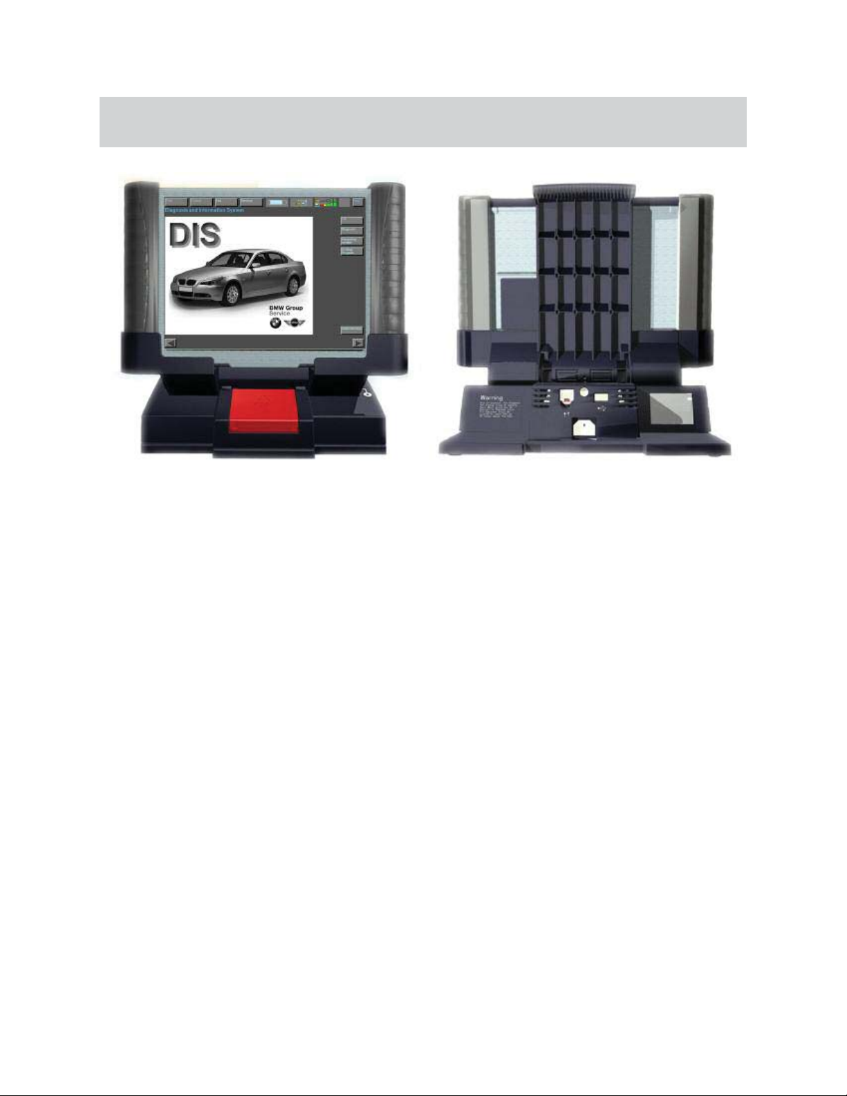
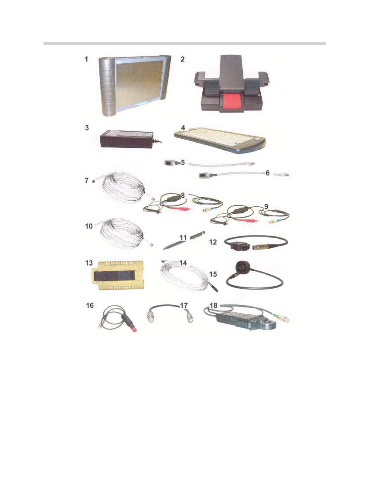
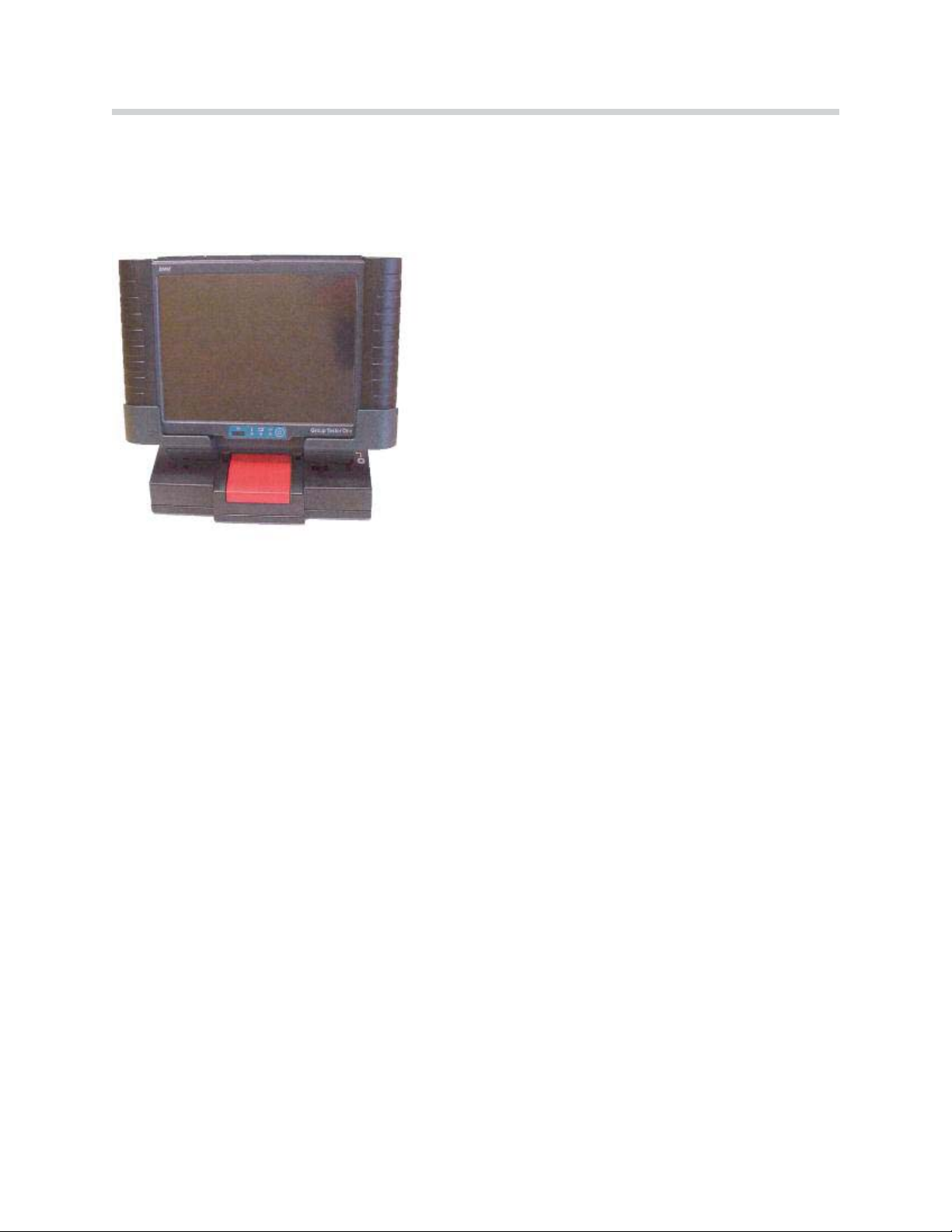
Group Tester One (GT1) . . . . . . . . . . . . . . . . . . . . . . . . . . . . . . . . . . . . . . . .4
Control Panel . . . . . . . . . . . . . . . . . . . . . . . . . . . . . . . . . . . . . . . . . . . . . . . . . .6
Monitor . . . . . . . . . . . . . . . . . . . . . . . . . . . . . . . . . . . . . . . . . . . . . . . . . . . . . . . .6
Control Block . . . . . . . . . . . . . . . . . . . . . . . . . . . . . . . . . . . . . . . . . . . . . . . . . .6
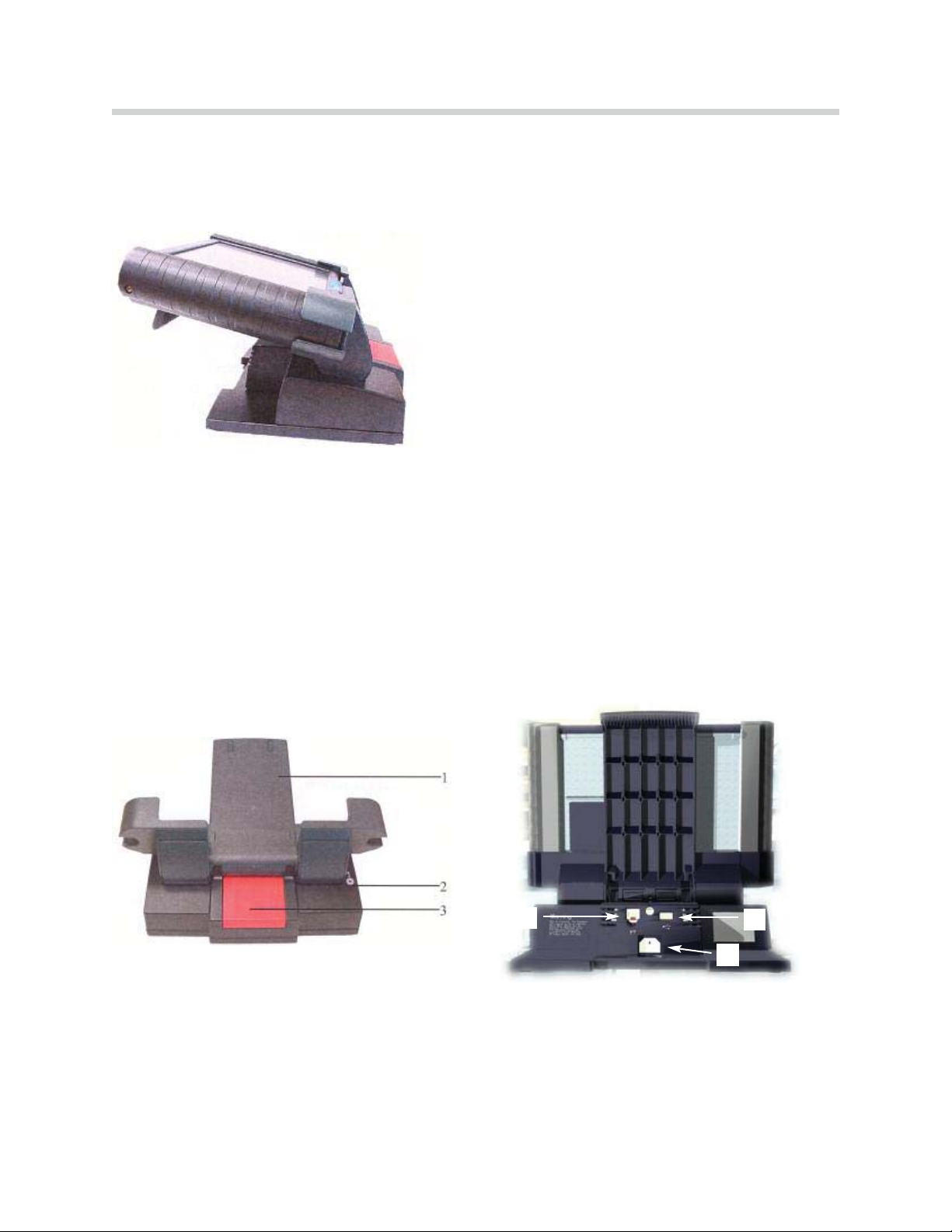
Control Panel Connections . . . . . . . . . . . . . . . . . . . . . . . . . . . . . . . . . . . . . .7
Power Supply . . . . . . . . . . . . . . . . . . . . . . . . . . . . . . . . . . . . . . . . . . . . . . . . . .7
DVD Drive . . . . . . . . . . . . . . . . . . . . . . . . . . . . . . . . . . . . . . . . . . . . . . . . . . . . .8
Docking Station . . . . . . . . . . . . . . . . . . . . . . . . . . . . . . . . . . . . . . . . . . . . . . . .8
Bench Power Unit . . . . . . . . . . . . . . . . . . . . . . . . . . . . . . . . . . . . . . . . . . . . . .9
Optical Keyboard . . . . . . . . . . . . . . . . . . . . . . . . . . . . . . . . . . . . . . . . . . . . . . .9
LAN Control Panel Cable (Crossed) . . . . . . . . . . . . . . . . . . . . . . . . . . . . .10
LAN Control Panel Adapter (Uncrossed) . . . . . . . . . . . . . . . . . . . . . . . . .10
LAN Control Panel Cable . . . . . . . . . . . . . . . . . . . . . . . . . . . . . . . . . . . . . . .10
MFK1 and MFK2 . . . . . . . . . . . . . . . . . . . . . . . . . . . . . . . . . . . . . . . . . . . . .11
Multi-Function Test Cable-MFK #1 . . . . . . . . . . . . . . . . . . . . . . . . . . .11
Multi-Function Test Cable-MFK #2 . . . . . . . . . . . . . . . . . . . . . . . . . . .11
Touch Pen . . . . . . . . . . . . . . . . . . . . . . . . . . . . . . . . . . . . . . . . . . . . . . . . . . . .12
OBD Diagnostic Cable . . . . . . . . . . . . . . . . . . . . . . . . . . . . . . . . . . . . . . . . .12
Diagnostic Head . . . . . . . . . . . . . . . . . . . . . . . . . . . . . . . . . . . . . . . . . . . . . .12
Vehicle Battery Adapter Cable . . . . . . . . . . . . . . . . . . . . . . . . . . . . . . . . . .13
Ammeter Clamp with Adapter . . . . . . . . . . . . . . . . . . . . . . . . . . . . . . . . . .13
Battery . . . . . . . . . . . . . . . . . . . . . . . . . . . . . . . . . . . . . . . . . . . . . . . . . . . . . . .14
Replacing the Battery . . . . . . . . . . . . . . . . . . . . . . . . . . . . . . . . . . . . . . .14
Diagnosing with the GT1 . . . . . . . . . . . . . . . . . . . . . . . . . . . . . . . . . . . . .15
GT1 Troubleshooting . . . . . . . . . . . . . . . . . . . . . . . . . . . . . . . . . . . . . . . . .16
Control Panel . . . . . . . . . . . . . . . . . . . . . . . . . . . . . . . . . . . . . . . . . . . . . . . . .16
Touch Screen . . . . . . . . . . . . . . . . . . . . . . . . . . . . . . . . . . . . . . . . . . . . . . . . .17
Plug-in Connections . . . . . . . . . . . . . . . . . . . . . . . . . . . . . . . . . . . . . . . . . . .17
Printer . . . . . . . . . . . . . . . . . . . . . . . . . . . . . . . . . . . . . . . . . . . . . . . . . . . . . . .18
Accessories . . . . . . . . . . . . . . . . . . . . . . . . . . . . . . . . . . . . . . . . . . . . . . . . . .18
Docking Station . . . . . . . . . . . . . . . . . . . . . . . . . . . . . . . . . . . . . . . . . . . . . . .19
Fault Codes . . . . . . . . . . . . . . . . . . . . . . . . . . . . . . . . . . . . . . . . . . . . . . . . . . .19
Diagnostic Head . . . . . . . . . . . . . . . . . . . . . . . . . . . . . . . . . . . . . . . . . . . . . .20
Group Tester One (GT1)
Revision Date:

Subject Page
Measurements Interface Box (MIB) . . . . . . . . . . . . . . . . . . . . . . . . . . . .21
Front Panel . . . . . . . . . . . . . . . . . . . . . . . . . . . . . . . . . . . . . . . . . . . . . . . . . . .22
Rear Panel . . . . . . . . . . . . . . . . . . . . . . . . . . . . . . . . . . . . . . . . . . . . . . . . . . . .22
GT1 Trolley . . . . . . . . . . . . . . . . . . . . . . . . . . . . . . . . . . . . . . . . . . . . . . . . . .23

3
Group Tester One
Group Tester One
Model: All
Production: All
After completion of this module you will be able to:
Identify the components of the GT1.
Demonstrate how to properly connect the diagnostic head via hardwire.

4
Group Tester One
The Group Tester One (GT1) is a portable diagnostic tools. It has the same processor as
the DISplus; a Pentium III, with 256 MB RAM and a 20 GB harddrive.
Other features include:
12.1TFT color display, 1024 x 768 resolution
Integrated PCMCIA card reader
Integrated chip card reader
Touch screen - same as DISplus
Workshop grade case
ASM-technology motherboard
Temperature operating range from 35ºF to 105ºF
2.5 hours of operation with a fully charged battery.
Can be powered by vehicle battery.
Weighs 7.7 lbs.
Group Tester One (GT1)

5
Group Tester One
1. Control Panel
2. Docking Station
3. Bench Power Unit (not used)
4. Optical Keyboard
5. LAN Control Panel Cable (Crossed)
6. LAN Control Panel Adapter (Uncrossed)
7. LAN Control Panel Cable (same design as 10)
8. Multifunction Cable MFK 1
9. Multifunction Cable MFK 2
10. LAN Docking Station Cable (same design as 7)
11. Touch Pen
12. Diagnostic Cable - OBD
13. Diagnostic Head
14. LAN Diagnostic Head Cable
15. Diagnostic Cable - 20 pin (not used)
16. Vehicle Battery Adapter Cable
17. Size 2 Adapter (for 50 A clamp)
18. Ammeter Clamp 50 A
Components of the GT1

6
Group Tester One
Control Panel
The control panel is the central component of the GT1. The operating system and the
application programs are stored here.
Monitor
The surface of the monitor is covered by a touch-sensitive plastic sheet that senses the
pressure of a finger or the touch pen and transfers it to the system.
Note: Use only your finger or the touch pen supplied to operate the touch
screen. If other objects are used, it may damage the GT1 Screen.
Control Block
The main control block of the GT1 control panel is located under the center of the touch-
screen. It consists of 1 on/off switch, 3 LEDs and the infrared receiver port. The infrared
port is the connection to the wireless keyboard used during programming.
The On/Off switch is used to switch the control panel on and off or to initiate a forced
switch-off. If a fault occurs that causes the unit to lock-up, you can shut down the unit
by holding down the on/off button for 5 seconds. This may cause the loss of operating
software, necessitating a reinstall (use only in an emergency).
The status of the switch does not affect the charging operation.
Located on the front of the Control Panel:
- PCMCIA interface (radio card slot in
left handle)
- Monitor with touch capabilities
- Control Block
- Battery Compartment (in right handle)

7
Group Tester One
The temperatureLED will glow red when the control panel is overheated. The control
panel will shut down approximately 10 seconds later. See the Owners Manual for restart
procedures.
The batteryLED will glow yellow during charging. It will switch off to signify the battery
is fully charged. It will flash yellow if excessive temperatures continue.
The operationLED will glow green when using an external power source, glow orange
when using the internal battery. A flashing orange LED signifies a discharged battery.
Alternately flashing orange/green LED denotes that the internal battery is defective or has
been removed.
Control Panel Connections
TOP Bottom
Power Supply
The control panel is supplied power from one of three voltage sources:
Internally from the battery (approximately 2.5 hours of operating time).
Externally from the bench power unit or the docking station.
Externally from the vehicle electrical system.
1. IR Interface
2. Temperature LED
3. Battery LED
4. Operation LED
5. ON/OFF Switch
1. DVD drive - DVD and CD-ROM compatible
2. VGA - external monitor connection
3. COM - future application
4. LAN - network or diagnostic head connection
5. USB (2) - future applications (approved PostScript printer)
6. Audio in - microphone
7. Audio out - speakers or headphones
8. Firewire - multimedia functions, future applications
9. Base Measurement - MFK 1 and MFK 2 or
External power supply from vehicle electrical system
1. Docking station interface
2. Bench power supply connection.
An optional power supply when not
using the docking station (not for MINI)

8
Group Tester One
DVD Drive
The DVD Drive is accessible from the top of the control panel. It accommodates DVDs
and CD-ROMs for installing programs, applications or updates of the control panel.
Note: When you open and close the DVD drive the control panel must be in the 14°
inclination position as shown, otherwise the drive tray or the disc may be
damaged. The suspension system for the drive is optimized for 14°. Do not
use the DVD unless the control panel is attached to the docking station.
Docking Station
The Docking Station is intended for stationary operation, it replaces the bench power unit
and provides the power supply. The Docking Station also provides the interfaces for con-
nection to a USB device and the LAN Network.
1. Docking interface for the Control Panel
2. Hinge - used to change viewing angle
3. Hinge Release
1. LAN connection
2. USB port
3. Power cord
12
3

9
Group Tester One
Bench Power Unit
As an alternative to the docking station, the bench power unit may be used to power the
control panel. The bench power unit consists of the built in connecting cable on the con-
trol panel, the power unit itself and a separate power cable. When the control panel
receives power from the bench power unit, the internal battery is simultaneously
charged.
Optical Keyboard
The keyboard uses an Infrared link to communicate with the GT1 control panel. It is used
only for service programs and can not be used in place of the virtual keyboard of the con-
trol panel. The keyboard must always face the control panel when in use and must be
less than 1 meter away from the control panel (IR). The keyboard uses 4 AA batteries as
an internal power supply.
Old batteries can leak and damage the keyboard. Always
keep fresh batteries in the keyboard (or remove when not
in use).
If more than one GT1 is in use in the workshop, the optical keyboard should be config-
ured to a specific GT1 control panel as follows:
1. Press and hold the identification key while pointing the keyboard at the control panel.
2. Press a numeric key, 0-7 on the keyboard. The control panel will now respond only
to commands from that keyboard.
If necessary the identification can be changed at any time following the above instructions.
CAUTION!!!

10
Group Tester One
LAN Control Panel Cable (Crossed)
The LAN control panel adapter (crossed) is approximately 30 cm long with a RJ45 con-
nector and a RJ45 socket. It is identified by a black (yellow on early units) stripe near the
socket and a label reading LAN Adapter BT X.This crossed cable is needed to be able
to communicate between the diagnostic head and the GT1.
LAN Control Panel Adapter (Uncrossed)
The LAN control panel adapter (uncrossed) is approximately 30 cm long with a RJ45
socket and a RJ45 connector. It can be identified by a gray stripe near the socket and a
label reading LAN Adapter 1:1.
LAN Control Panel Cable
The LAN diagnostic head cable is 10 meters long and has a RJ45 connector and an
orange plug connector.
LAN Cable Crossed
LAN Cable Uncrossed
Lan Cable (orange color coded end)

11
Group Tester One
MFK1 and MFK2
The MFK1 and MFK2 cables are the main leads used for measurements. They are simi-
lar in appearance, but have different measurement capabilities.
Only one cable, either MFK1 or MFK2 (visual markings) may be connected to the control
panel at one time unless a Measurement Interface Box (MIB) is used.
Both Both large positive cable ends of MFK 1 and MFK 2 include a button used to hold
the measured value on the display screen.
Multi-Function Test Cable-MFK #1
MFK 1 is used to measure:
Voltage - up to 50 Volts
Current - up to 2 Amps
Resistance
Diode Testing
Frequency
Period
Duty Cycle
Pulse Duration
Oscilloscope Measurements
Multi-Function Test Cable-MFK #2
MFK 2 is used to measure:
Voltage - up to 500 Volts
Frequency
Period
Duty Cycle
Pulse Duration
Oscilloscope Measurements
MFK1
MFK2

12
Group Tester One
Touch Pen
The Touch Pen is an ergonomic operating aid for the touch screen that makes it easier to
operate the displays.
OBD Diagnostic Cable
The Diagnostic Cable is used to connect the diagnostic head to a vehicle via the OBD II
diagnostic connector (upper right).
Diagnostic Head
The Diagnostic Head enables operation of the diagnostic interface via either radio or
cable communication.
1. Connection for Voltage Measurements
2. LED 1 (Power)
3. Connection for Voltage Measurements
4. LED 2 (Status)
5. Connection for LAN Cable
6. Connection for TD Cable
7. LED 3 (Excess Temperature)
8. Connection for Diagnostic or OBD Cable
LED 1 G reen LED 2Yellow LED 3Red Function Rem arks
ON ON ON Initialization R ecorderButton Green
ON OFF OFF Pow erUp
ON Flashing O FF Standby
ON ON OFF C onnected
Flashing ON OFF SelfTestorUpdate
Flashing E xcess Tem peratureFault

13
Group Tester One
Vehicle Battery Adapter Cable
The vehicle battery adapter cable is used while in the vehicle as a power supply for the
GT1. This cable does not charge the GT1s internal battery.
Ammeter Clamp with Adapter
The ammeter clamp and adapter can be used to measure the amperage of a circuit
inductively. There are two amperage clamp available: one measures up to 50 amps, the
other up to 1000 amps.
1. Recorder Button (For Future Use)
2. Nine Pin Interface (For Future Use)

14
Group Tester One
Battery
Power is supplied by the integrated battery when the control panel is not connected to an
external power source. The battery must be charged to insure uninterrupted use of the
control panel as a mobile test unit. The battery is charged automatically as soon as the
control panel is placed in the docking station or connected to the bench power supply.
While the battery is being charged the BatteryLED illuminates in yellow.
To achieve the longest possible service life for the integrated battery, it must be fully
charged, then discharged for normal use. Once a month the battery should be formed
which entails fully discharging the battery, then fully recharging it.
To formthe battery:
Disconnect the bench power unit from the control panel or undock from the docking
station or disconnect the docking station from a power source.
Fully discharge the battery, by leaving the control panel ONuntil all the LEDs are
out.
Dock the control panel or supply power to the docking station or connect the bench
power unit.
Charging is complete when the BatteryLED goes out.
Note: Always replace a defective battery with a new battery. Never operate the
control panel with out a battery (it acts as a buffer). Sudden interruption of
power my cause the control panel to loose the installed operating system.
Replacing the Battery
1. Switch off power and undock control panel.
2. Remove screw on right hand handle.
3. Pull off handle.
4. Remove battery.
5. Press down on the retainer for the connector
and carefully remove connector.
6. Connect new battery.
7. Insert new battery in handle.
8. Reinstall handle on control panel.
9. Completely charge new battery.

Diagnosing with the GT1
(hardwired to the diagnostic head)
15
Group Tester One
For hardwire connection three cables must be used:
LAN control panel adapter UNCROSSED
LAN control panel adapter CROSSED
LAN Diagnostic head cable
The three cables MUST be connected in the particular order shown below.
1. Diagnostic Head
2. Control Panel
3. Docking Station
4. LAN Control panel adapter UNCROSSED
5. LAN Control panel adapter CROSSED
6. LAN Diagnostic Head Cable

16
Group Tester One
Control Panel
Note: The power supply to the control panel cannot be measured at the open
docking contact because the power is through-connected via a proximi-
ty switch only when the control panel is docked.
Forced Switch-Off may be used only in the case of spe-
cial faults. Continued use of this feature may cause oper-
ating system failure and device shut down. Normal shut
off is performed by pressing the ON/OFF switch for
2 seconds.
Sym ptom PossibleCauses Rem edy
The system “c rashes”;the
hourglass no longerchanges
back tothe cursor arrow ;no
operation p ossible
InternalFaultIf‘normal’sw itch-offnotp ossible,use aforced sw itch-off
(press the on/offsw itch forapprox.5 seconds)toswitch the
controlpaneloffand on again.
Withthe controlpanel
docked,the “O p e ration”
LED lightsuporange.
Docking station pow er
supplyisinterrupted.
ControlPanelisnot
supplied withpowervia
the docking contact.
C heck whetherpow erispresent.Insertthe pow erplug
correctly.
C heck the sp ring contactsfordirtorforeign objects.
To setup acorrectconnection,undock and then redock
the controlpaneltow orthree times(also see S ection 7.3).
Ifno faults can be determined,send aFaultR eportFax.
“T e m p e rature” LED lightsup
red;controlpanelsw itches
off.
Excess internal
tem peraturecircuit
breakeractivated.
Movethe controlpanelto a coolerroom and allow itto cool
dow n adequately.S w itch the controlpanelon again.
Ifthe “T e m p e rature” LED flashes yellow wit
houtthe
presence ofhigh am bienttem perature,send aFaultReport
Fax.
“B a ttery” LED flashes yellow
for10 seconds on startup;
controlpaneldoes notstart.
Afterthe controlpanel
shutsitselfoff,thereis
stillexcess tem perature.
Movethe controlpanelto a coolerroom and allow itto cool
dow n adequately.S w itch the controlpanelon again.
Ifthe “b a ttery” LED flashes yellow withoutthe presence of
high am bienttem perature,send aFaultR eportFax.
System does notpow erup
com pletely;g ets‘stuck’with
an errorm essage.
Internalrun error Sw itch the controlpaneloff(press the on/offsw itch for5
seconds =forced sw itch off)and then on again.
Ifthe system stillfreezes,you mustreinstallthe Base CD in
accordance w ith Secti
on 3.5.3.
Ifthisfaultoccursrepeatedly,send aFaultR eportFax.
Aftercom pletedischarge and
docking atthe docking
station,the system does not
pow erup.
Profound discharge of
the battery.
Afteraprofound discharge and docking atthe docking
station,you mustwaitapprox.3minutes beforethe system
can be pow ered up
GT1 Troubleshooting
CAUTION!!!

17
Group Tester One
Touch Screen
Important: Only use finger or the touch pen to operate the screen. Screen
damage may result otherwise.
Plug-in Connections
Important: Never use force to insert the connectors. The connectors on the
measuring and diagnostic cables are marked with a red dot that
must be aligned with a corresponding dot on the socket.
Sym ptom PossibleCauses Rem edy
The curso r does notrespond
(does notfollow finger
contact).
Touch controller
defective orsystem
‘crashed’.
Sw itch the controlpaneloff(press the on/offsw itch for5
seconds =forced sw itch-off)and then on again.
Ifthe faultpersistsoroccursmorefrequently,
send aFault
ReportFax.
The touch screen rem ains
dark;no errorm essage by
m eans on LED .
Touch screen isinthe
energy-saving m ode.
B acklighting failure.
Notafault.Thescreen imagereappears w hen the touch
screen istouched.
Ifyou glance sidew ays atthe touch screen,yo u can detect
vague characters.
Send aFaultR eportFax.
The curso r arrow isnot
located beneaththe pointof
touch (touch offset)
Touch the controllerset
incorrectly.
The touch controllerm ustbe calibrated inthe
“A d m inistration”window .Press the “C a librating touch
screen” button,enterthe p assw ordandf
ollow the
instructions thataredisplayed.
Ifthisdoesnoteliminatethe problem ,send aFaultReport
Fax.
Incorrectpixelcolors Individualtransistors
defective.
Individualpixelsofincorrectcolorsaretolerable. Ifthe
entirescreen row s orcolum ns areincorrect,send aFault
ReportFax.
Sym ptom PossibleCauses Rem edy
50 Aammeterclip cannotbe
connected
C onnectorsonthe
am m eterclipdonotfitin
the socket.
Use the size 2 ad ap ter
Cable connection viaLAN
interface todiagnostic head
interrupted
Plug-in connections on
LAN adapter defective
C heck thatthe plug-in connections arecorrectly seated and
undam aged.C heck whetherthe plug-in connection viathe
LAN controlpaneladapter(uncrossed)has been
established.

18
Group Tester One
Printer
Accessories
Sym ptom PossibleCauses Rem edy
LocalPrinterdoes notprint Printerconnected to
docking station,control
panelundocked.
Printerisdefective.
Dock the controlpanelorinsertthe USB cableonthe
printerinthe controlpanel.C heck thatthe connection is
correctly seated.
Inthe “A d m inist
ration”window ,press the “S e lf-test”button
and selectthe “P rinterconnection”function from the m enu
disp layed. The printershouldprinta page withthe heading
“PS”.Ifthisdoesnotoccur,check the cable connection to
the printer.
NetworkPrinterdoes not
print.
Networkprinter
connected viaLAN cable
todocking station;
controlpanelundocked.
Radiolink todiagnostic
head established
Cablelink todiagnostic
head established.
PrinterDefective.
Dock the controlpanel.
Disconnectthe cable connection tothe diagnostic head
and established a connection tothe networkprinterin
accordance with Section 4.4.8.
Disconnectthe cable connection tothe diagnostic head
and established a connection tothe networkprinterin
accordance with Section 4.4.8.
Inthe “A d m inistration”window ,press the “s e lf-test”button
and selectthe “p rinterconnection”function from the m enu
disp layed. The printershouldprinta page withthe heading
“PS”. Ifthisdoesnotoccur,chack whetherthe correctIP
address forthe printerisentered inthe “A d m inistration –
Networkconfiguration”window .
Sym ptom PossibleCauses Rem edy
No m easurem ents possible
withMFK1.
M easuring head defective. In“Administration”,run aself-testofthe MFK1.
Ifan errorm essage isissued regarding the m easurem ent
system orm easuring cable,send aFaultReportFax.
No m easurem ents possible
withMFK2.
M easuring head defective. In“Administration”,run aself-testofthe MFK2.
Ifan errorm essage isissued regarding the m easurem ent
system orm easuring cable,send aFaultReportFax.
No inputpossibleviathe
opticalkeyboard.
No IR connection possible
orbatteries discharged.
C heck whetherthe transm itand receive w indow s ofthe
infrared connection arecovered. C hange the distance
betw een the devices. Replace the batteries inthe optical
keyboard.
Ifno connection can be set
up,send aFaultR eportFax.

19
Group Tester One
Docking Station
Fault Codes
Sym ptom PossibleCauses Rem edy
No pow ersup plytothe
controlpanel(“O p e ration”
LED does notlightup in
green on docking when
sw itched on).
No pow ersup plyor
pow ersup plyplug
disconnected.
Docking contactsdirty
Foreign objectprevents
the perfectseating ofthe
plug-incontacts.
Proximityswitch is
defecti
ve,does not
through-connectpow er.
Pow ersupplyunit
defective
LED defective
Insertthe pow ersup plyplug.Press the on/offsw itch.
Carefullyclean the contactsonthe docking station witha
lint-free cloth.
Rem ove the foreign object.
Send aFaultR eportFax
“B a ttery” LED does notlight
up orange whensw itch off.
Batteryisfullycharged.
Docking contactsdirty.
Pow ersupplyunit
defective.
LED defective.
NotaFault.
Carefullyclean the contactsonthe docking station witha
lint-free cloth.
Send aFaultFax
Send aFaultR eportFax
Codes Fault Group
000 System error from UNIX operating system
100 Fault in the measurement system, internal
200 Fault in the EDIC application
300 Fault in the system technology
400 Fault in the TOROS application
500 Fault in the measurement system application
800 Run error
900 Internal error

20
Group Tester One
Diagnostic Head
Sym ptom PossibleCauses Rem edy
No connection possible
(LED 1ondiagnostic head
isdark).
No Pow ersupplyofthe
diagnostic head viavehicle
electricalsystem s.
Firstcheck the plug-incontacton the BM W orOBD
diagnostic cableandits connection tothe vehicle.
Sw itch on the ignition.
Ifthe LED stilld oes notlight
up,send aFaultReportFax.
C onnection tothe
diagnostic head not
possibleorfaulty(LED 2
flashes yellow );no
diagnostic head is
recognized (see
“A d m inistration,Diagnostic
H ead Allocation”w indow ).
The diagnostic head
cannotbe connected.
Interference due to
excessive distance from
the vehicle;inthe case of
radiolink,mayalso b e due
toexternalradiosources or
absorption.
Diagnostic head software
defective.
IncorrectIPaddress when
the diagnostic head was
changed.
Radio cardinthe
diagnostic head defective.
Radio cardinthe control
panelisdefective.
C heck the correctconnection ofthe cables atthe diagnostic
head.
Changethe location ofthe diagnostic head and,ifnecessary,
ofthe controlpanel.
Ifthisdoesnotrem edy the fault,change the connection typ e.
Ifthereisstillno connection,send aFaultReportFax.
Performareinstallation in accordance with Section 7.7
C heck the IPaddress inthe “A d m inistration,Network
configuration”window .
Ifp ossible,use the second diagnostic head to check the radio
link.Ifthe connection can be established,the cardinthe first
diagnostic head isdefective.Send aFaultReportFax.
Ifp ossible,use the second diagnostic head to check the radio
link. Ifno connection can be established withthis head either,
the cardinthe controlpanelmightbe defective.
Using asuitabletool(such as ascrew driver),prythe coveroff
the radio cardslotinthe lefthandleofthe controlpanel(see
fig.7.1);you willthen se one green and one yellow LED on the
radioboard. Ifthe green LED islit,the radioboardisOK.If
the yellow LED isflashing rapidly, datatransm ission isbeing
formedcorrectly.
Ifthe LED s areinanyotherstate,send aFaultReportFax.
LED 3Flashing Red Interiortem peratureofthe
diagnostic head istoo
high.
Terminatethe diagnosis.Terminatethe connection and allow
the diagnostic head to cooladequatelybeforeusing itagain.
LED 1 flashing rapidlyGeneralfaultinthe
diagnostic head.
Send aFaultReportFax.
“R ecorder”button on the
back lightsup ingreen.
Onlywhile booting. N otaFault.
Thisbutton has notfunction atthistime.
This manual suits for next models
1
Table of contents