BN Products SIGMA DCM 40 Operating instructions
1
SIGMA
DCM 40 MECHANICAL REBAR CUTTING
MACHINE
OPERATING AND MAINTENANCE MANUAL
Supplied by
BN Products-USA, LLC
3450 Sabin Brown Rd. Wickenburg, AZ 85390 (800) 992-3833 or (928) 684-2813

2
TABLE OF CONTENTS
Heading : Page No:
1. Machine Assembly. 4
1.1.Machine assembly. 4
1.2.Sequence of machine operating procedures. 4
2. Technical data. 6
3. Equipment to accompany the machine. 6
4. Correct and wrong cutting forms 7
5. Disallowed operations on the machine 8
6. Warranty conditions: 9
7. Protectors to be used during operation of the machine. 10
7.1. Protective clothing. 10
7.2. Work clothing. 10
8. Transportation of the machine: 10
9. Checks & adjustments on the machine and
Blade replacement. 11
9.1 .V-Belt adjustment. 11
9.2. Demounting of V-Belt. 12
9.3. Blade replacement. 12
10.Maintenance of the Machine:
10.1. Daily maintenance of the machine. 13
10.2. Weekly maintenance of the machine 13
10.3. Monthly maintenance of the machine. 14
10.4. 6-Month maintenance of the machine. 14
10.5. Annual maintenance of the machine. 14
11.Fault analyses and remedies: 15
12.Electrical diagram. 17
13.Materials list. 18
14.Earthing connection 23
3
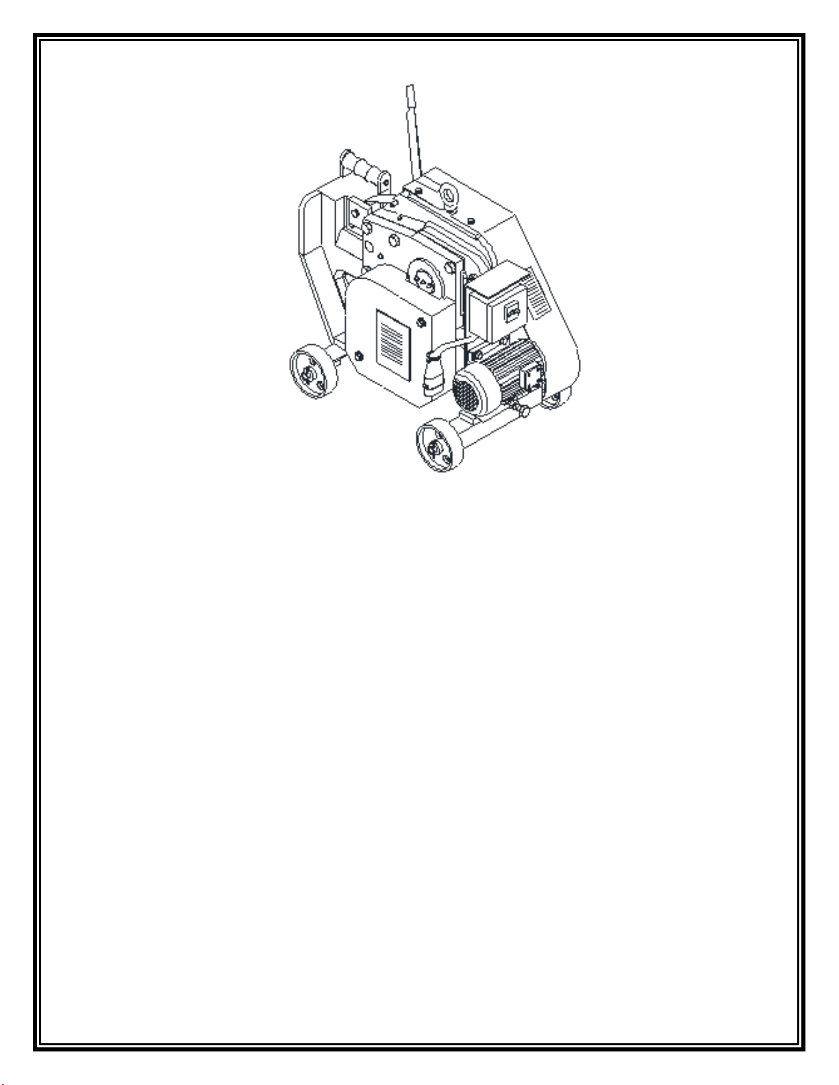
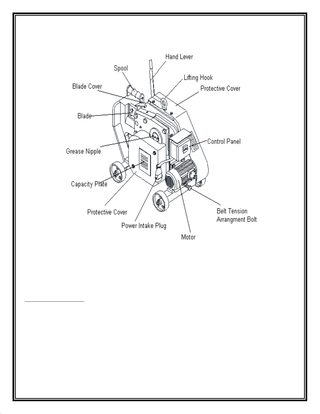
DCM 40 MECHANICAL REBAR CUTTING MACHINE :
DCM 40 Mechanical Rebar cutting machine is manufactured only for the purposes of
cutting the Rebar. The use of the machine for other purposes is not permitted. The machine
can be easily transported within the short distances under the site conditions by the help of
the wheels.
Important warnings:
•Please read the operation and maintenance manual thoroughly.
•The machine should be operated by the trained people.
•The machine should be shut off and the electrical connection will be cut off during
maintenance and lubrication of the machine, blade replacement and belt tension
adjustments are conducted.
•The maintenance and lubrication requirements of the machine should be observed.
4
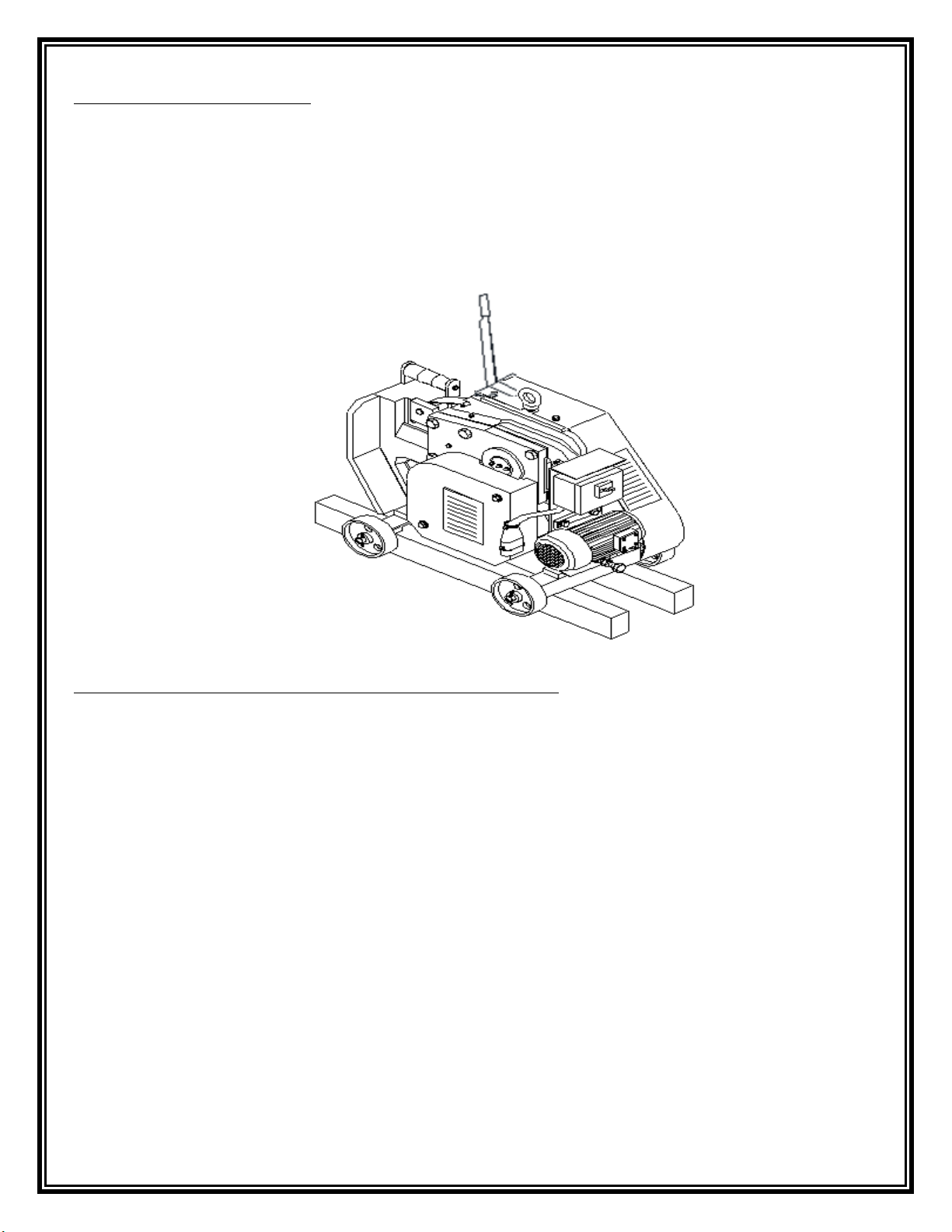
1.1 Machine Assembly:
•The machine is to be balanced by feeding with wedges underneath in a manner to
disconnect the wheels from the ground on a smooth surface. (see Figure 1)
•The electrical connection of the machine should be installed by the authorized people.
Operating voltage should be 415 V. See page 23.
•The earthing should be provided for the safety purposes. The machine cannot be
operated without the earthing connection. See page 23.
1.2 Sequence of machine operating procedures :
•Make sure that the machine is installed in accordance with the assembly rules.
•Plug on the power supply cord (4 X 4 sqmm) the feeding line of main power.
•Grounding is made for safety. Do not operate machine without grounded power.
•Switch on the machine and check if the direction of rotation is as per indicated arrow. If
not you have to change the terminal of phases by means of qualified Electrician.
•Please study the Capacity Plate of machine which indicates no of rebar’s corresponding
to dia of rebar.
•Lift the protective shield of the machine & place the rebar to be cut close the protective
shield. Adjust the retainer position so that rebar to be cut is held between fixed &
Movable blade.
•In Case the rebar are more than one. Place one bar above the other. (Indicated In Fig 4)
•Press the foot pedal once and cutting will take place.

5
Start- Stop Buttons :
Figure : 2
Machine cutting capacity :
Diameter Of Rebar
650 N/mm2
850 N/mm2
Ø40(#11) X 1
Ø32(#10) X 1
Ø32(#10) X 1
Ø25(#8) X 1
Ø25(#8) X 1
Ø16(#5) X 1
Ø12(#4) X 4
Ø12(#4) X 3
Ø10(#3) X 4
Ø10(#3) X 3
Ø6(#2) X 6
Ø6(#2) X 5

6
2. TECHNICAL DATA
•Machine Type: DCM 40
•Machine Designation: Mechanical Rebar Cutting Machine
Blade Size:
Width: 85 mm
Length: 85 mm
Thickness: 20 mm
Belt Used:
V-belt: A-49
Machine Dimensions:
Width: 560 mm
Length: 1020 mm
Height: 750 mm
Weight: 350 kg
Motor specifications:
Motor power: 5.5 Kw
Motor Revolution: 1730 rpm
Motor Supply: 220/460 V
Frequency: 60 Hz
3. EQUIPMENT TO ACCOMPANY THE MACHINE
•Allen Key 14mm 1 Piece
•500 cm grease pump 1 Piece
•Cutting Blade 2 Piece
7
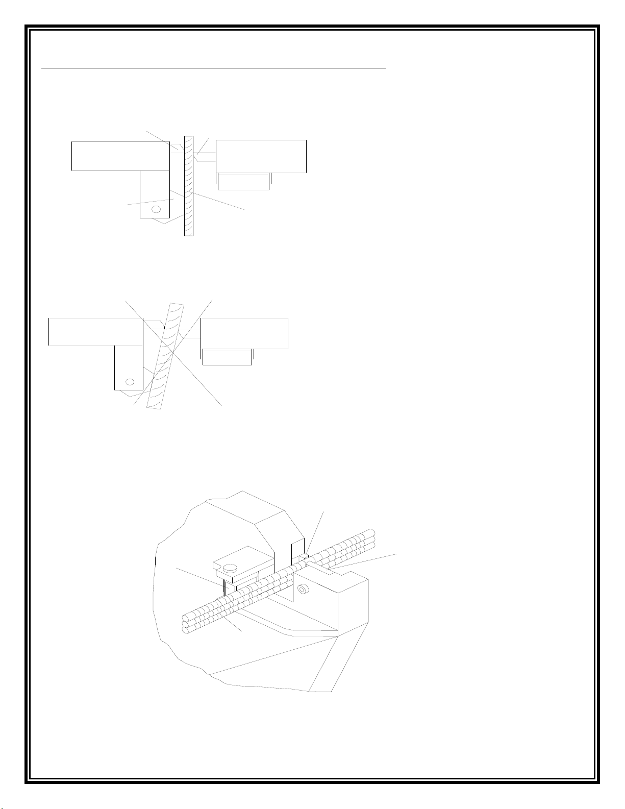
4. Correct placement of the steel between the blades:
Figure: 3
CORRECT CUTTING
Wrong placement of the steel between the blades:
WRONG CUTTING
For multi-cutting operations, place one steel on the top of the other in an amount indicated
in the capacity plate. Figure: 4
SHIELD
STEEL
MOVABLE
BLADE
FIXED
BLADE
MOVABLE BLADE
FIXED BLADE
SHIELD
STEEL

8
5. DISALLOWED OPERATIONS ON THE MACHINE:
▼No cutting work should be conducted without closing the Protective Shield.
▼The machine will be powered off and the electrical system will be switched off
during a blade replacement or maintenance work.
▼No one should be allowed to stand in front of the machine during a cutting
work.
▼The limbs should be kept away from the cutting blades.
▼At any given time the hammer, meter, compass, lever and similar construction apparatus
should not be inserted in between the blades when the machine is running.
▼The machine should not be started up if it is wet.
▼The Rebar Dia and corresponding numbers of rebar as indicated in the capacity plate of
the machine should be strictly observed for cutting purposes.
▼The Rebar to be cut should be held against the fixed blade and retainer.
▼In case of rebar to be cut are more than one always put them one on the top of other
▼The machine should not be started up when the cover of the switch box is open.
▼The default settings of the thermal current adjustment field as provided by the
machine manufacturer should not be tempered with.
▼The machine should not be operated without the earthing connection.
▼The machine should not be started when the protective covers are in
disassembled position.
▼The unauthorized and untrained people should not be permitted to work on the
machine.
▼The machine should not be operated without lubricants.
▼The warning labels affixed on the machine should not be torn down.
▼No cutting should be applied by using blunt and cracked blades.
▼ The machine should not be cleaned by applying air.

9
6. WARRANTY CONDITIONS:
The manufacturer accepts the warranty and liability only if the following conditions are
observed
▼The Guards fitted on the machine are never removed.
▼The warning signals are observed.
▼The machine is not operated without lubricants.
▼The machine is not started without installing the earthing connection.
▼Only the genuine spare parts from manufacture should be used for the
replacement of the malfunctioned parts of the machine.
▼The conditions specified as the safety measures are observed.
▼The disallowed operations are avoided.
▼The machine is installed in accordance with the assembly conditions.
▼The machine is operated by the trained and authorized people.
▼No of rebars corresponding to rebar dia as indicated in capacity plate are
observed.
▼The electrical connection is installed by the authorized and competent people.
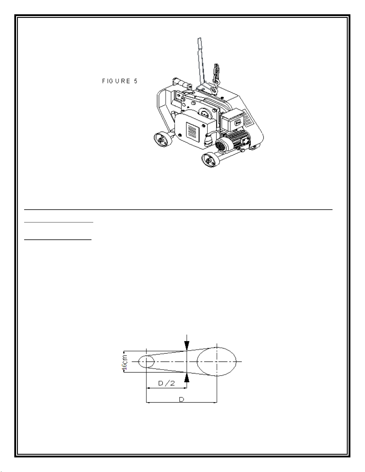
▼The machine is carried in accordance with the handling conditions (See Figure 5
▼ For multi-cutting purposes, bars are put one on the top of the other.
▼The machine is serviced in accordance with the maintenance conditions.
.

10
7. PROTECTORS TO BE USED DURING OPERATION OF THE MACHINE
7.1The protective clothing:
•Hard hat
•Glasses
•Safety Shoes
•Gloves
The above mentioned protectors are to be used. Otherwise, there is a risk of injury and body
harm.
7.2 Work clothing:
The objects having the risk of getting caught and seized up while working on the machine are
listed below, which may cause injury if not observed.
Long hair, dress with long sleeves, jewelry on arm, aprons with long bottoms, jewelry
protruding from the body.
8. TRANSPORTATION OF THE MACHINE
The machine should be carried and transported by means of the forklift, traveling crane or
EOT cranes. The forklift may only be used when the machine is enclosed in the box. To carry
the machine in the boxed situation, a wedge should be inserted underneath the machine in a
manner not allowing the wheels of the machine to contact with the box surface or the wheels
will be pulled out. The steel rope chain and polyester sling shot should be used for lifting the
machine. The lifting from the box ring on the machine should be used for lifting without a
box. The experienced expert people and subcontractors should be employed in the lifting
works.
WARNING!!!
The machine should be moved without vibration. The machine should not be carried in the
wet places. Any parts lost or damaged during the transportation process should be notified to
the manufacturer in the form of a report
•When using the lifting and handling equipment, the maximum carrying capacity of
these equipments will be taken into consideration.
•The weight gravity center of the equipment should be taken into consideration during
the lifting.
•The warning signals on all of the handling equipments should be observed.
11
9. CHECKS & ADJUSTMENTS ON THE MACHINE AND BLADE
REPLACEMENT
9.1 Belt adjustment:
The V-belts placed on the machine are loosened over time. Also the belt adjustment is
necessary as it will be misadjusted after the belt replacements. If the belt is loose, it causes
noise during the running of the machine and shortens the life time of the belt. The machine
fails to cut if the belt is too loose. However, it may cause the roller bearings on the motor
and body to warm up if the belt is set very tightly. The tightness of the belt should be
adjusted from the motor adjustment bolt, so that the distance between the two sides of the
belt should be 9 cm when it is pressed at the middle of both of the pulley centers.

12
9.2 Sequence of demounting of the V-belt from the machine:
1. Demount the protective cover at the pulley side of the machine.
2. Loosen the motor connection bolt.
3. Unscrew the nut of the motor adjustment bolt.
4. Make the pulleys close to each other by turning the motor adjustment bolt.
5. Remove the V-belt firstly from the small pulley and then from the bigger one.
6. To fit the belt in position, fit it firstly to the big pulley and then to the smaller one.
7.Set the tension of the belt by means of the motor tension bolt.
8. Tighten the motor connection bolt.
9. Complete the belt replacement process by fastening the protective cover.
Şekil : 8
9.3. Blade replacement
Remove first the movable blade and then the stationery blade while replacing the blades.
Ensure that the cutting edges are matching each other while fitting the blades.
FIGURE 9
:
Figure 8:
V- BELT
MOTOR ADJUSTMENT BOLT
PULLEYS

13
10. MAINTENANCE OF THE MACHINE:
It is of great importance that the maintenance is performed properly in order to increase the
service life of the machine and ensure a safe cutting work. We recommend that each user
installs a reliable system for the control and maintenance of the machine. The following
instructions are provided only for reference purposes. The machine should always be
lubricated with grease.
10.1 Daily Maintenance of the Machine:
•Check the machine for the noise when running.
•If the machine is operated in open air conditions, protect from rain when it is
rainy.
•Clean the blade spaces with a brush.
•Check the blades for bluntness and cracks, and replace if necessary.
10.2 Weekly Maintenance of the Machine:
•Replace the broken grease nipples fitted on the machine with the new ones.
•Lubricate the machine with the grease pump using the grease nipples fitted on the
machine.
•Check the blade bolts for tightness.
•Check the machine belts for their tensions
10.3 Monthly Maintenance of the Machine:
•Check the bolt connections on the machine for their tightness.
•Demount the protective covers of the machine and lubricate the movable
sections of the gear parts, engagement parts and foot pedal.
•Demount the protective cover and clean the steel shaving if any accumulated
between the movable sections.
10.4 6- Month Maintenance of the Machine:

14
•Demount the protective covers of the machine and remove the
contaminated oil on the movable parts and re-lubricate them.
•Check the movable running gears, engagers and carriers, machine bodies
and machine components for bluntness, breaks and cracks.
•Check if cavities are formed due to wear on the bronze bearings of the
machine, and replace the bronze bearings if so.
•Check the roller bearings of the machine for proper functioning
•For the proper functioning of machine it is necessary to change all the
roller & Bronze bearing every six month.
10.5. Annual Maintenance of the Machine:
•Check if cavities are formed due to wear on the bronze bearings of the
machine, and replace the bronze bearings if so.
•Check the roller bearings of the machine for proper functioning and replace if
necessary.

15
11. FAULTS AND REMEDIES:
The faults to arise during the operation of the machine and their reasons and remedies are
NO
FAULT
DESCRIPTION
REMEDY
1.
The power switch is
interrupted frequently
1. The power switch may be
interrupted due to overheating of
the motor.
2. There may be a short circuit in
the machine or installation.
3. The motor protection switch may
be malfunctioned and does not
activate the starters.
1. Check the belts for their
tightness.
2. Check if there is a short circuit.
.
3. Check the power switch.
Replace it if defective.
2.
The machine does not
start up
1. There may be an interruption in
the cabling.
2. There may be a
short circuit in
The motor.
3. The electrical network to
which the machine is connected fails
to receive phase
1. Check the cabling connections.
2. Check if there is a short circuit
by cutting off the electrical
connection of the machine.
3. Check the fuses on the
electrical panel.
3.
The machine fails to cut.
1. The belts may be loose or torn.
2. The engagement is not active.
3. The gear is broken off.
4. The eccentric axle or lever may
be broken off.
5. The cut steel is not in the
required size or strength.
1. Check the belts.
2. Replace the engagement
driving springs.
3. Check the gears.
4. Check the eccentric axle or
lever.
5.Check the cut steel acc. to the
cutting capacity plate
1. The engagement threads may be
worn.
2. The belts may be loose.
1. Replace the engagement.
2. Check the belt for its tightness.

16
4.
Machine is noisy when
running.
3. The roller bearings may be
failed.
4. The machine is not lubricated
enough.
5. The motor fan cover may be
crushed.
3. Check the roller bearings.
4. Check and lubricate the machine.
5. Check the motor fan cover.
5.
The machine frequently
causes the blade bolt to
be broken off.
1. The bearings to which the blades
are connected may be widened.
1. Check the blade connecting
points and repair if necessary.

17
12. ELECTRICAL DIAGRAM:

18
13. MATERIALS LIST:
No
Part Number
Part Name
Quantity
1
DCM40-01
Main Body
1
2
DCM40-02
Roller Bearing(6309 ZZ)
2
3
DCM40-03
Helix Pinion Gear
1
4
DCM40-04
10 X 10 X 94 Wedge
1
5
DCM40-05
Roller Bearing(6211 ZZ)
1
6
DCM40-06
Helix Gear
1
7
DCM40-07
Roller Bearing (6313 ZZ)
1
8
DCM40-08
Spur Pinion
1
9
DCM40-09
12 X 12 X 38 Wedge
1
10
DCM40-10
Washer M16
1
11
DCM40-11
Allen Screw M16 X 40 Lg
1
12
DCM40-12
Eccentric Shaft
1
13
DCM40-13
Carrying Arm
1
14
DCM40-14
Carrying Arm Bush
1
15
DCM40-15
Blade Carrier
1
16
DCM40-16
Blade
2
17
DCM40-17
Allen Screw M16 X25
1
18
DCM40-18
Cover Bush
1
19
DCM42-19
Cover Plate
1
20
DCM40-20
Bush Retaining Plate
1
21
DCM40-21
Allen CSK M6 X 20Lg
4
22
DCM40-22
Hex Screw M20 X 65 Lg
6
23
DCM40-23
Protective Cover RH
1
24
DCM40-24
Hex Nut M10
14
25
DCM40-25
Housing Bush
1
26
DCM40-26
Spur Gear Bush
1
27
DCM40-27
Spur Gear
1
28
DCM40-28
Spur Gear Insert
1
29
DCM40-29
Allen Screw M8 X 50 Lg
4
30
DCM40-30
Ring
1
31
DCM40-31
External Circlip Dai 75
1
32
DCM40-32
Clutch
1

19
33
DCM40-33
Engagement Pin
1
34
DCM40-34
Clutch Spring
1
35
DCM40-35
Spring Retaining Cover
1
36
DCM40-36
Allen CSK M10 X 35
2
37
DCM40-37
Pulley A2-7”
1
38
DCM40-38
Motor Connection Stand
1
39
DCM40-39
Hex Screw M20 X 100
1
40
DCM40-40
Hex Nut M20
1
41
DCM40-41
Hex Nut M16
2
42
DCM40-42
Hex Screw M16 X 100
1
43
DCM40-43
Electric Motor 5.5Kw ,1730
Rpm,220/460V, 60 Hz
1
44
DCM40-44
8 X 10 X 36 wedge
1
45
DCM40-45
Pulley A2-5”
1
46
DCM40-46
Grub Screw M10 X 20
1
47
DCM40-47
V-Belt A49
2
48
DCM40-48
Flywheel
1
49
DCM40-49
Washer M12
1
50
DCM40-50
Allen Screw M12 X 40
1
51
DCM42-51
Axle Segment
1
52
DCM40-52
External Circlip Dia 20
3
53
DCM40-53
Allen Screw M16 X 80
1
54
DCM40-54
Wedge
1
55
DCM40-55
Spool Pin
1
56
DCM40-56
Spool Bracket
1
57
DCM40-57
Spool/Roller
1
58
DCM42-58
Blade Protective Cover
1
59
DCM40-59
Hex Screw M10 X 50
1
60
DCM40-60
Axle
1
61
DCM40-61
Retainer
1
62
DCM40-62
Lock Pin
1
63
DCM40-63
Stud M10
1
64
DCM40-64
Needle Bearing
1

20
65
DCM40-65
Hand Lever
1
66
DCM40-66
Spring
1
67
DCM40-67
Disengagement Mechanism
1
68
DCM40-68
Disengagement Pin
1
69
DCM40-69
Disengagement Spring
1
70
DCM40-70
Disengagement Block
1
71
DCM40-71
Spacer Dia 20 X 21 Lg
1
72
DCM40-72
Lever
1
73
DCM40-73
Protective Cover LH
1
74
DCM40-74
Hex Screw M10 X 15
4
75
DCM40-75
Mounting Angle
2
76
DCM40-76
Wheel
4
77
DCM40-77
Washer Dia 50
4
78
DCM40-78
Starter
1
Table of contents
Other BN Products Cutter manuals


Popular Cutter manuals by other brands


Intec
Intec ColorCut SC6500 installation instructions

Elliott
Elliott PTTC Series Operating and maintenance instructions

Hitachi
Hitachi CM5SB Handling instructions

Wacker Neuson
Wacker Neuson RCP 20 Operator's manual

Central Forge
Central Forge 41711 Assembly & operating instructions

Makita
Makita 4112HS instruction manual