Intec ColorCut SC6500 User manual

ColorCut SC6500
Unpack and Installation Instructions
Doc number: T09375_EN_B
Date: 3January 2024

3 January 2024
SC6500 1-1 Installation Procedure
1.1 Unpack Instructions.................................................................................................. 1-2
1.2 Installation Requirements......................................................................................... 1-4
1.2.1 Minimum space requirements.................................................................. 1-4
1.2.2 Power Requirements................................................................................ 1-5
1.2.3 Workstation Hardware Requirements...................................................... 1-5
1.3 Installation Precautions............................................................................................. 1-6
1.4 ColorCut Pro Installation........................................................................................... 1-8
1.4.1 Accessory check......................................................................................1-8
1.4.2 Cutter preparation....................................................................................1-9
1.4.3 Fuse replacement (if required)............................................................... 1-13
1.4.4 Tool Carriage and Tools installation ....................................................... 1-14
1.5 Software installation................................................................................................ 1-16
1.5.1 ColorCut Pro Installation........................................................................ 1-16
1.5.2 ColorCut Pro Activation..........................................................................1-20
1.6 Connecting and powering on the cutter..................................................................1-21
1.6.1 Turning on the cutter..............................................................................1-21
1.6.2 Connecting to computer.........................................................................1-21
1.6.3 USBorEthernetConnectionconrmation ............................................. 1-22
1.7 Checking the installation......................................................................................... 1-23
1.7.1 Test Cut..................................................................................................1-23
1.7.2 Calibration of the Vision3 sensor offset to the Cutting Blade................. 1-25
1 Unpack and Installation Instructions
3 January 2024
SC6500 1-2 Installation Procedure
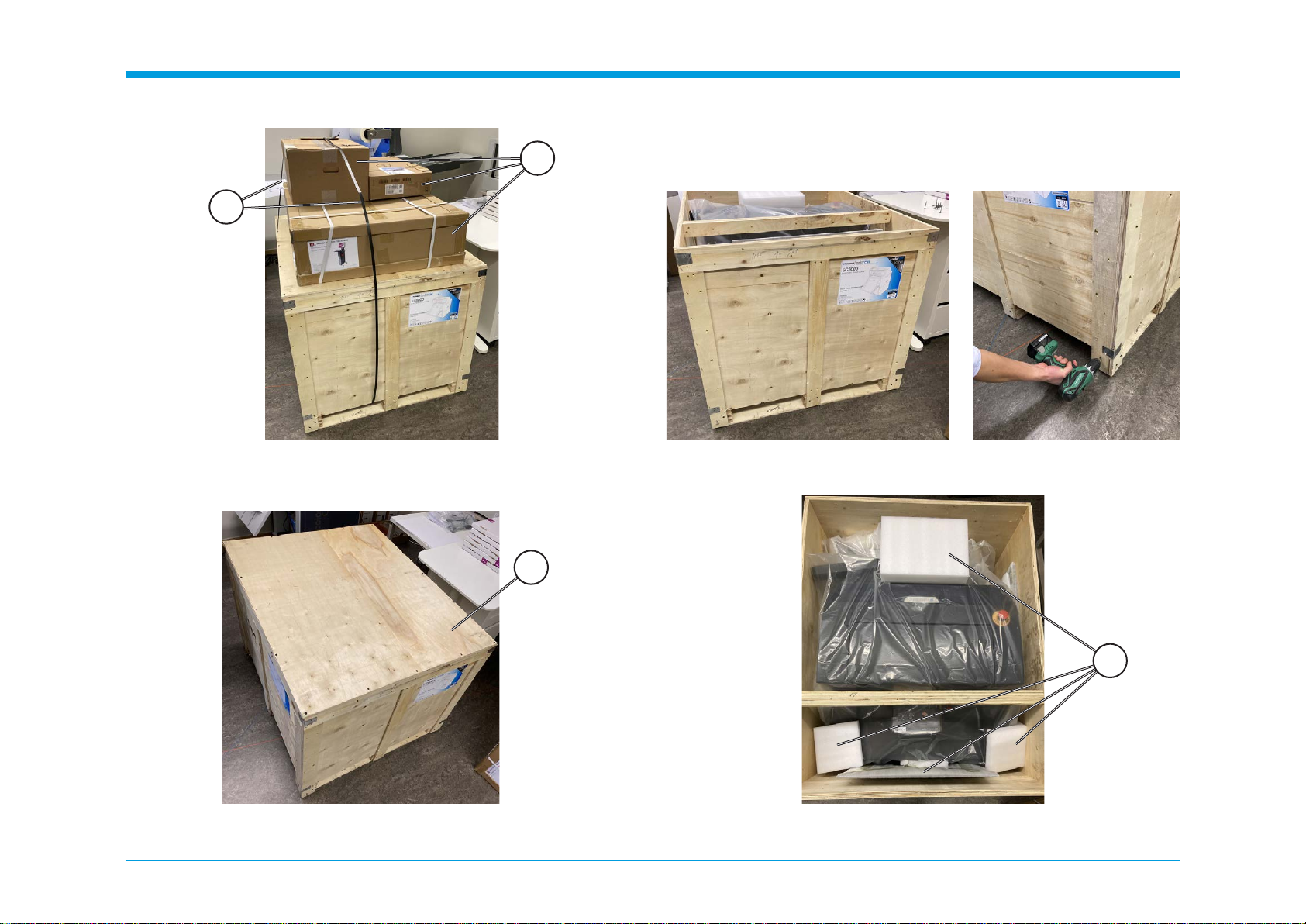
1.1 Unpack Instructions
1. Remove the straps [A] and boxes [B] on top of the main crate.
2. Remove black screws on top of the lid and remove the lid [C].
3. Remove black screws along the bottom of the crate.
4. Remove all the loose pieces [D] inside the box.
D
C
A
B

3 January 2024
SC6500 1-3 Installation Procedure
5. Lift the crate [E] up to remove it.
6. Remove the plastic wrap [F].
E
F
Intentionally blank

3 January 2024
SC6500 1-4 Installation Procedure
1.2 Installation Requirements
1.2.1 Minimum space requirements
1. Working Space is different to Machine dimensions.
2. EnsurethereissufcientspaceattherearoftheSC6500toeasilyload
sheets and adjust the media side guides.
3. EnsurethereissufcientspaceabovetheSC6500toeasilypressthe
Emergency Stop Switch in case of a problem.
4. Ensure there is space by the side of the machine to operate the control
panel and the feeder control button.
5. Ensure there is space for the retractable exit tray to be opened, without
causing an obstruction to walkways.
Exit tray

3 January 2024
SC6500 1-5 Installation Procedure
1.2.2 Power Requirements
1.
Ensure that a power outlet is available nearby the system, fused to
withstand the system’s combined rated current.
2.
The current consumption can be seen on the machine labels. For example:
if the machine label says “100-240 V, 3.4-1.7A” then the rated current is
3.4 A at 100 V and 1.7 A at 240 V.
3. Make sure to route power cords to avoid people from tripping on them.
4. Avoid using excessively long extension cords.
5. Make sure the machine is grounded.
1.2.3 Workstation Hardware Requirements
Compatible Vector Programs
Adobe Illustrator® * Corel Draw® **
PC Windows CS6; CC
CC 2014
CC 2015
CC 2017
CC 2018
CC 2019
CC 2020
CC 2021
CC 2022
CC 2023
X4 - X8
2017 - 2023
Mac OS CC 2017
CC 2018
CC 2019
CC 2020
CC 2021
CC 2022
CC 2023
*Does not support illegal copies of Adobe Illustrator
**Full version only. Does not support “Home and Student”, “Essentials” edition or illegal
copies of CorelDRAW
1. Multicore Intel processor with 64-bit support
2. Windows 10 Professional / Windows 11 Professional x64 bit
3.
4 GB of RAM (8 GB recommended (As supplied with ColorCut Pro
Server Station))
4. Minimum display resolution: 1024x900
5. Recommended Display Resolution: 1280x960 or higher.
(Screens with resolutions such as: 1152x900, 1024x900, 1280x960,
1440x900, 1440x960, 1440x1024, 1440x1080, 1600x900, 1600x1080,
1600x1280, 1920x1080 or higher)
6. 2x available USB Ports (Note KB & Mouse often use a port each so
factor this in)
PC directly connected to ColorCut must have Wi-Fi capability for Direct con-
nection to Vision3 Camera Sensor. (for PC users with no Wi-Fi currently a
USB Wi-Fi dongle included)
Compatible OS Versions
PC Windows 10 Pro or 11 Pro – 64 bit
Mac OS version 10.11 (El Capitan) - Mac OS version 13 (Ventura)

3 January 2024
SC6500 1-6 Installation Procedure
1.3 Installation Precautions
Safety measures
Please read the information and safety measures carefully prior to installation
and initial operation of the unit.
• Do not place any magnetic objects in the vicinity of the cutting head;
otherwise uniform contact pressure may not be ensured.
• Do not remove the connection cable to the computer while cutting is in
progress.
• Relieve the pressure on the pressure rollers when not in use by moving
the pressure lever up.
• Donotopenorreachintotheunitwhenitisconnectedtoelectricitysupply.
• Neveropenthecasing and do not makeanymodicationstotheunit
yourself.
• Ensure that neither liquids nor metal objects are put inside the SC6500.
• Ensure that the wall socket used is grounded.
• Ensure that the connected voltage (100-240V) does not deviate by more
than ±10%. Otherwise install a voltage stabiliser.
• Remove the power plug from the unit if it will not be in use for a longer
period of time.
• Never reach into the unit in the vicinity of the blade holder during the
cutting operation.
• Stop any cutting jobs in progress before re-adjusting the blade holder.
• AlwaysensurethattheAutoSheetCutterremainsinaccessibletochildren
during operation and never leave the unit or individual parts of it switched
on without supervision.
• Do not touch the tip of the cutting blade to avoid injury.
• Alwaysplacetheunitonastablebaseorusethesuppliedstandtoprevent
it from falling down.
•
Disconnect from the power supply during thunderstorms; it can be
damaged or destroyed by electrical surges caused by lightning.
• Do not sit or step on the stacker tray. Stacker will break or machine will
tilt over. The maximums load for the stacker tray is 15 kg.
• Do not open covers while the machine is running.
• Do not move machine while the machine is running.
• Becautiouswhenthetoplidisopen.Priortoaccessingtheinterior,always
ensure that the cutter is turned off and disconnected from power supply.
• This equipment is not suitable for use in locations where children are
likely to be present.
• Do not use emergency stop button for regular operation of the Cutter.
The emergency stop button is designed for immediate stop solely for
emergency situations to ensure the safety of all individuals involved.
To reset the emergency stop button rotate it clockwise direction and pull it
back upwards to its original position. The emergency stop button should
onlybe resetafteraddressing andresolvingtheemergencycondition that
triggered its activation.
Emergency stop button
3 January 2024
SC6500 1-7 Installation Procedure
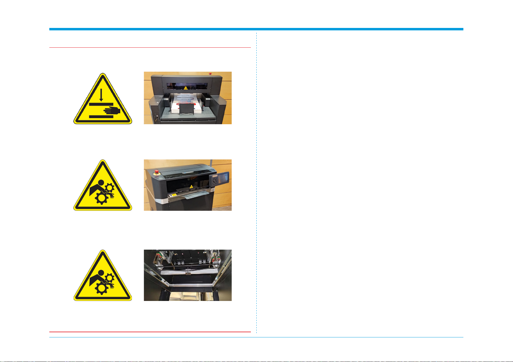
Warning: PINCH / CRUSHING HAZARD!
There are “Pinch Hazard” stickers on the SC6500 to remind the user to pay
extra caution when the machine is running:
• Do not ever put your hand under vacuum belt area while machine main
switchisON.Vacuumfeedbeltgoesupanddown.Handorngerscan
be crushed.
• Paperloadtablegoesupanddown.Donotloadwhilemachineisrunning.
• Keepngersandhandsawayfromthemovingcarriage.Thecarriage
change direction quick and have lot of force.
• Keep the cover closed while running.
• Keep hair away from the outfeed area. Hair entanglement hazard.
• Keepngersandhandsaway frommovingpartsunderneathintopof
the storage area.
Safety measures, continued

3 January 2024
SC6500 1-8 Installation Procedure
1.4 ColorCut Pro Installation
1.4.1 Accessory check
Item Qty Description
11 Left Side Frame
21 Front Filler Strip
31 Right Side Frame
41 Central Support Brace
51 Internal Shelf
61 Front Door
71 Base
81Accessory box (incl. USB Cable, Ethernet Cable, Power Cord,
Calibration Pen Tools, Blade Holder, Creasing Tool & Blades)
91Stand Assembly Box (incl. Allen (hex) key, Spanner, Allen Bolts
(hex), Washers, nuts, screws)
10 1 Tag Reduction Plate
4
5
8
6
7
9
1
10
2 3
3 January 2024
SC6500 1-9 Installation Procedure
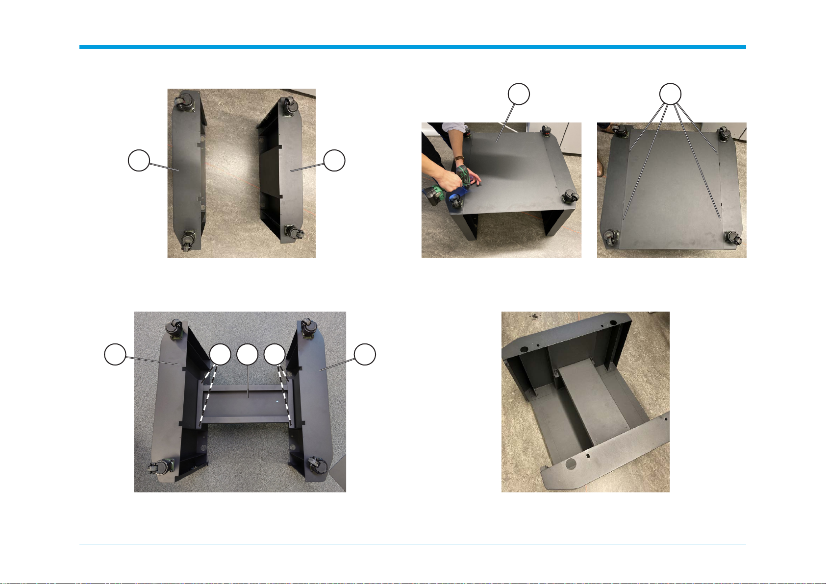
1.4.2 Cutter preparation
1.
Take the side frame pieces [A] and place them with the casters upwards.
3. Placethebasepanel[D]ontothebottomofthestand,alignallxing
holes and screw it loosely in place using remaining type screws (4x) [E],
then fully tighten all screws.
4. Turn the assembly over with casters on the ground.2.
Place the Central Support Brace [B] in between the side frame pieces [A].
Using the Allen screws (4x) and washers (4x) hand tighten the support
bracetothesideframes[C],thenusingallenwrenchfullytightenallxings.
A
A BC C A
D E
A

3 January 2024
SC6500 1-10 Installation Procedure
5. PlacetheInternalShelf[F]ontheCentralSupportBrace,alignallxing
holes and screw it loosely in place with supplied screws (4x) [G], then
fully tighten all four screws.
6.
On the left side of the unit locate two holes for door piece. Locate bottom
pin and top sprung pin on the door piece. 8. Push down the sprung loaded pin [J] on the door, slide the hinge into
the frame. Once positioned, gently release so the pin locates in the hole.
F
H
I
J
G
7. Place the bottom pin [H] of the door into the bottom slot [I].
3 January 2024
SC6500 1-11 Installation Procedure
Caution:
It is recommended that minimum of four people carry out this task.
Caution:
Avoid topple risk!
Cutter must be bolted securely to the cabinet stand.
Warning:
Do not lift the unit from the bottom but use the handles [K] on the sides!
Pinch risk:
Keep ngers away from base of cutter when being lowered!
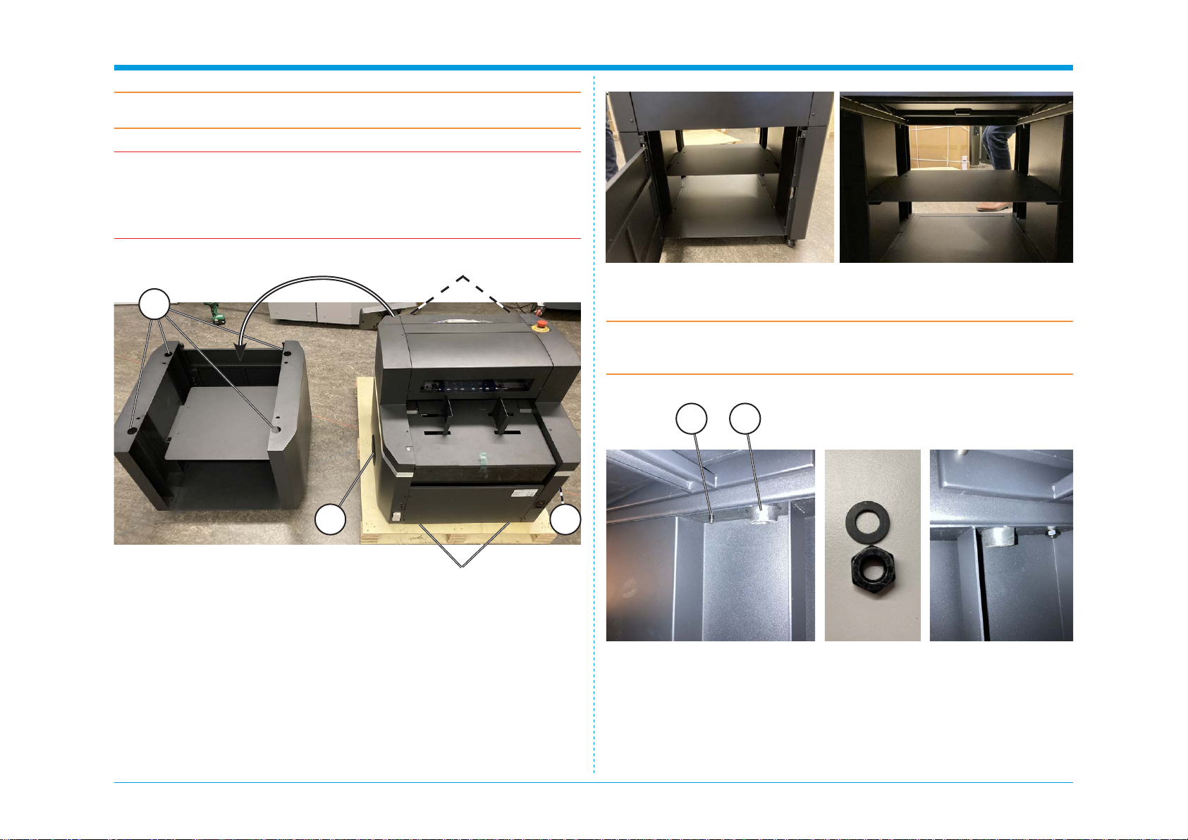
9. Remove the front drawer for easier access for lifting the unit.
10. The main unit has rubber feet (4x) [L] that match with holes (4x) [M] on
the support unit; these serve as guides to ensure that the main unit is
properly placed on top. Carefully lift the main unit by handles [K] with
one person on each side and one at front and back and place it onto
the support unit.
11.
Once the top half of the cutter is on the stand, secure the top to the stand.
To do so open the door and reach inside the machine.
12.
Locate screws (4x) [N] on the sides and install washers (4x) and nuts (4x).
LN
K K
M
Lifting point
Lifting point

3 January 2024
SC6500 1-12 Installation Procedure
14. On the outfeed side locate screws (2x) [Q].
Q
R
13. Retrieve Front Filler Strip [O] and install it above the door with screws
(2x) [P].
OPP
15. Retrieve Tag Reduction Plate [R] from accessory box and slide it on to
the screws (2x) [Q].
Note:
Tag Reduction Plate is a removable extension that provides more sup-
port to the sheet being moved back and forth. This means the sheet stays
atterandsectionsofthecutoutarelesslikelytopopoutofthesheet.This
allows for less tabs or in some cases, no tabs will be required at all, hence
increasing productivity of the machine. See operator manual for more details.
3 January 2024
SC6500 1-13 Installation Procedure
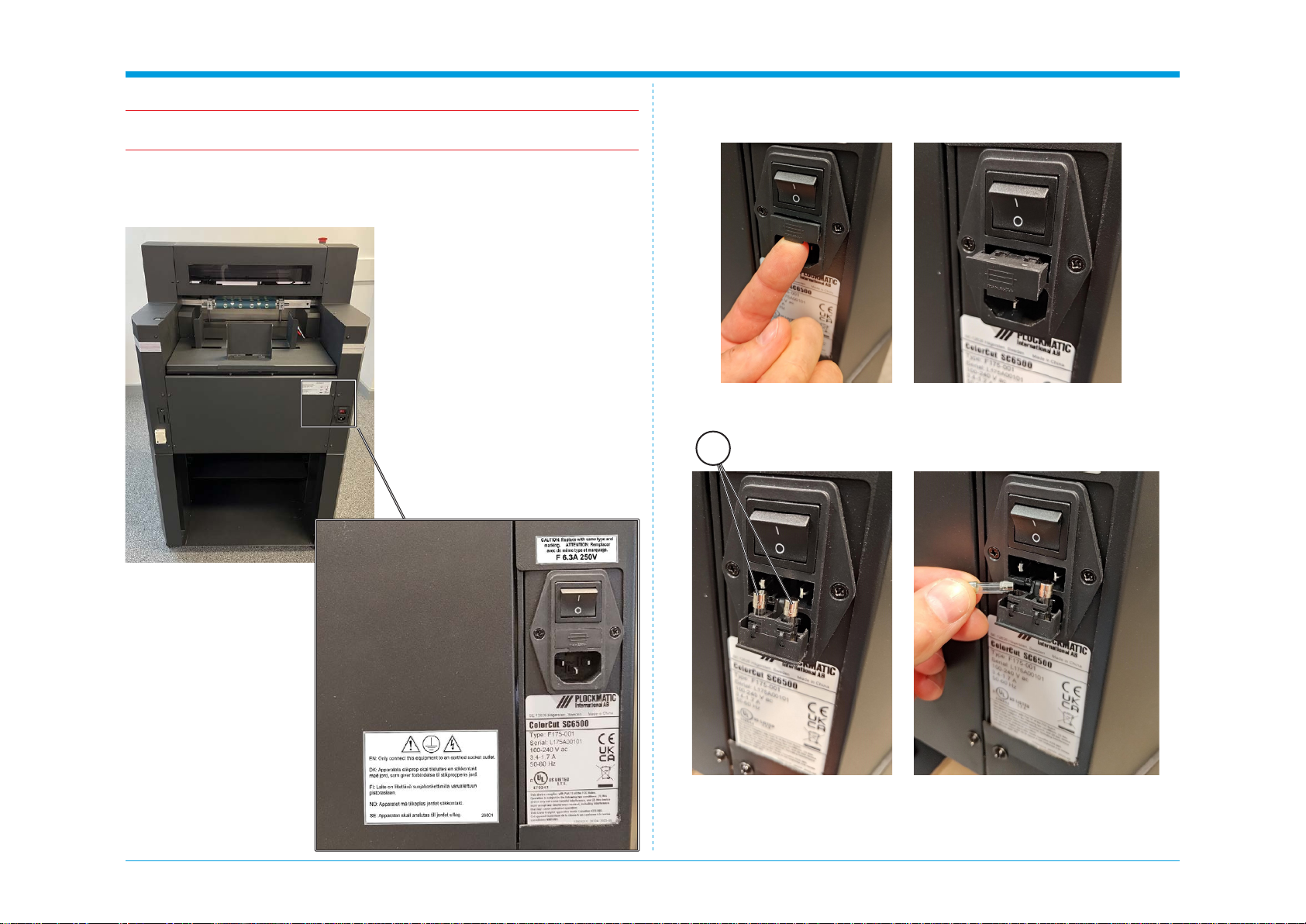
1.4.3 Fuse replacement (if required)
Warning:
Make sure the power cord is unplugged before replacing the fuse!
The SC6500 is shipped with a F 6.3 A fuse installed.
This fuse works in 100-240 Vac environments.
Procedure:
1. Opentheinletlterfuseholdercover.
2. Replace the fuses [A] (2x).
A
3 January 2024
SC6500 1-14 Installation Procedure
Bracket to hold tool
Tool Holder
Bracket to hold tool
Top
Side
Tool Holder
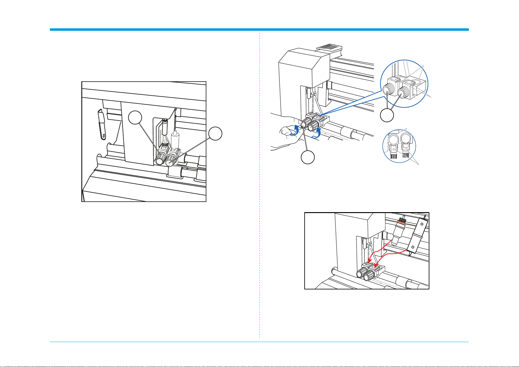
1.4.4 Tool Carriage and Tools installation
The tool carriage is mounted on a bar, located at the front of your SC6500
cutter that spans across the cutting area. TheTool carriage contains two tool
holders, each independently controllable. Each Tool holder enables you to
installorswitcheasilyandefcientlybetweenarangeoftools.
These tools may include a blade holder, or multiple blade holders if required,
a creasing tool and a pen for calibration.
EachToolholderhasadifferentdiameter.Position1’stoolsdonottinPosi-
tion2.ThesuppliedBladeHolderisdesignedtotinToolposition1.Youwill
require a different (optional) Blade Holder for Tool Position 2 to mount two
cutting blades simultaneously.
ConverselythecreasingtoolsuppliedisdesignedtotspecicallyinTool
Position 2.
Therefore; Tool Holder Position 1 [A] is typically the primary position for the
blade holder and cutting blade. Tool Holder Position 2 [B] is typically used
with the Creasing Tool.
Tools installation
1.
To install a tool into your ColorCut SC6500 loosen the tool holder’s thumb
screw[C]sufcientlytoenableabladeholderorcalibrationpentobe
insertedinToolposition1uptoitsange(OrCreasingToolinposition2).
2.
Push the Blade Holder or Calibration Pen all the way into the tool
holder position 1 until the tools’ ange completely touches the up-
per part of the holder.
Push the creasing tool all the way into tool position 2, until the creasing
toolangecompletetouchestheupperpartofthetoolholder.
A
B
C
C

3 January 2024
SC6500 1-15 Installation Procedure
3.
Make sure that the tool bracket is engaged on top of the tool’s
ange,andthentightenthescrew.
It is important, the Bracket to hold the Tool, is over the Flange as this
will hold the tool down. (If the Flange is above the bracket that holds the
tool, the tool height will be incorrect and the tool may gradually move up
during operation).
4. AfterttingtheBladeToolinposition1,repeatthesameprocessforthe
Creasing Tool in Position 2.
Flange
Bracket to
hold tool Tool holder
NO
YES
Intentionally blank

3 January 2024
SC6500 1-16 Installation Procedure
1.5 Software installation
The ColorCut Pro software is a professional cutting package that creates
cutting les directly from Illustrator or CorelDRAW using the vector lines
you have drawn, ColorCut Pro communicates directly with your cutter and
ultimately cuts your jobs.
There are two installation versions of ColorCut Pro, a plug-in (which requires
Adobe Illustrator® (MAC or PC) or CorelDRAW® (PC)) which creates the cut-
ting jobs directly from your vector lines and can either send your jobs directly
tothecutter(PConly)orcreateacutlethatcanberetrievedatanytime
using a QR code (automatically added to the sheet) (MAC & PC clients) then
users can cut a different computer (acting as a production server).
ColorCut Pro Software for your ColorCut Cutter is supplied on the included
CD, however it may also be downloaded from Plockmatic Customer Center.
Note: ColorCut Pro requires a Minimum display resolution: 960×830.
1.5.1 ColorCut Pro Installation
1. Run the installation program: SetupColorCutPro.exe
Thesetupprogramrequiresvariousconrmationsfortheinstallationofthe
program.
On some computers you could be asked the system administrator’s pass-
word to execute the installation, in the case you do not have this information;
contact the technician who administrates your system.
2. To start the installation of the ColorCut Pro software, click the [Next>]
button.
3.
By default the ColorCut Pro software will automatically install intoAdobe
Illustrator if it is installed on your computer.
4.
If you haveAdobe Illustrator, then the installation has completed and click
[No] on the dialogue box asking you if you wish to review the CorelDRAW
installation instructions.
5. If you have CorelDRAW, skip to the next page.
3 January 2024
SC6500 1-17 Installation Procedure
6. If you haveAdobe Illustrator, then the installation has nished; go to
Section 1.5.2.
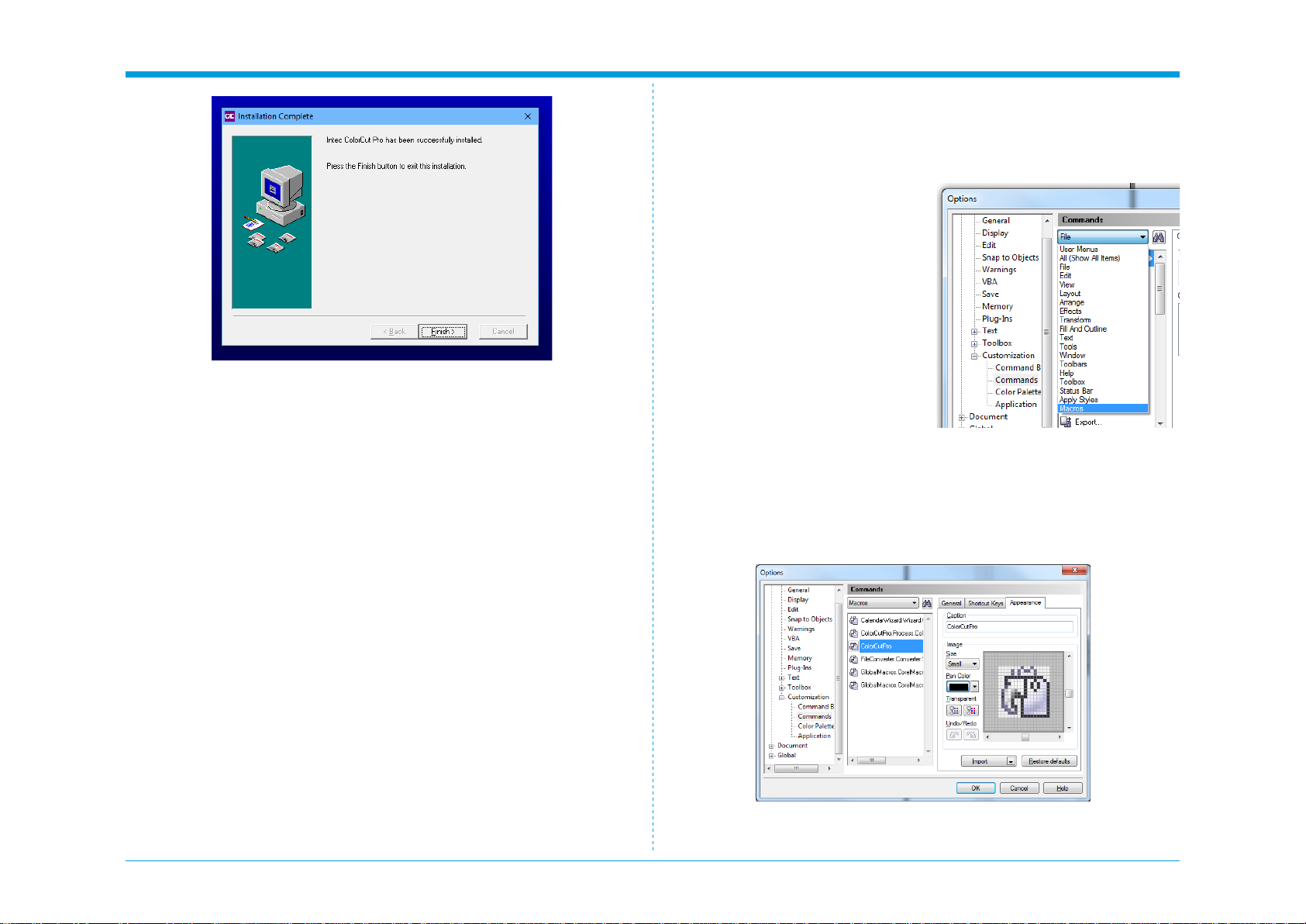
1.
Open CorelDRAW then click on the
Tools menu, and select Options.
2.
From the Options dialogue box,
select: Customization and under
this, click Commands
3.
In the panel on the right, select
macros from the drop down menu.
4. Select either:
- colorcutpro.process.
colorcutproall
- colorcutpro.process.colorcutpro
ColorCut Pro installation for CorelDraw
Skip this section if you have installed ColorCut Pro for Adobe Illustrator.
As part of the ColorCut Pro installation, the plug-in’s to CorelDRAW are
installed, however you need to add a shortcut into CorelDRAW.
The ‘colorcutpro.process.colorcutproall’ version exports the entire drawing
however the desired way to work is with layers
The ‘colorcutpro.process.colorcutpro’ version only exports the currently se-
lected layer. Unless you want to export the entire drawing. If you are unsure,
we recommend using the ‘colorcutpro.process.colorcutpro’ version.
5.
On the appearance tab menu (Under caption), change the name to
ColorCutPro. This is the name that will appear on the menu.

3 January 2024
SC6500 1-18 Installation Procedure
6. On Appearance tab, click [Import].
7. From the [Import] drop down, select [Files] at the bottom.
8. Navigate to:
For 32bit users of CorelDRAW C:\Program Files (x86)\PlockMatic Group\ColorCutPro 5
For 64bit users of CorelDRAW C:\Program Files\PlockMatic Group\ColorCutPro
and select the icon as shown.
The le path may alter.
9. Open Shortcut Keys Tab. Place the mouse cursor at New Shortcut Key
inputledandclickthenholddowntheAltkeyandtypeC.
10. To add ColorCutPro icon to your tool bar click on the ColorCutPro Com-
mand from the Macro list, press and hold the left mouse button and drag
the icon next to the printer icon on the tool bar and release.
3 January 2024
SC6500 1-19 Installation Procedure
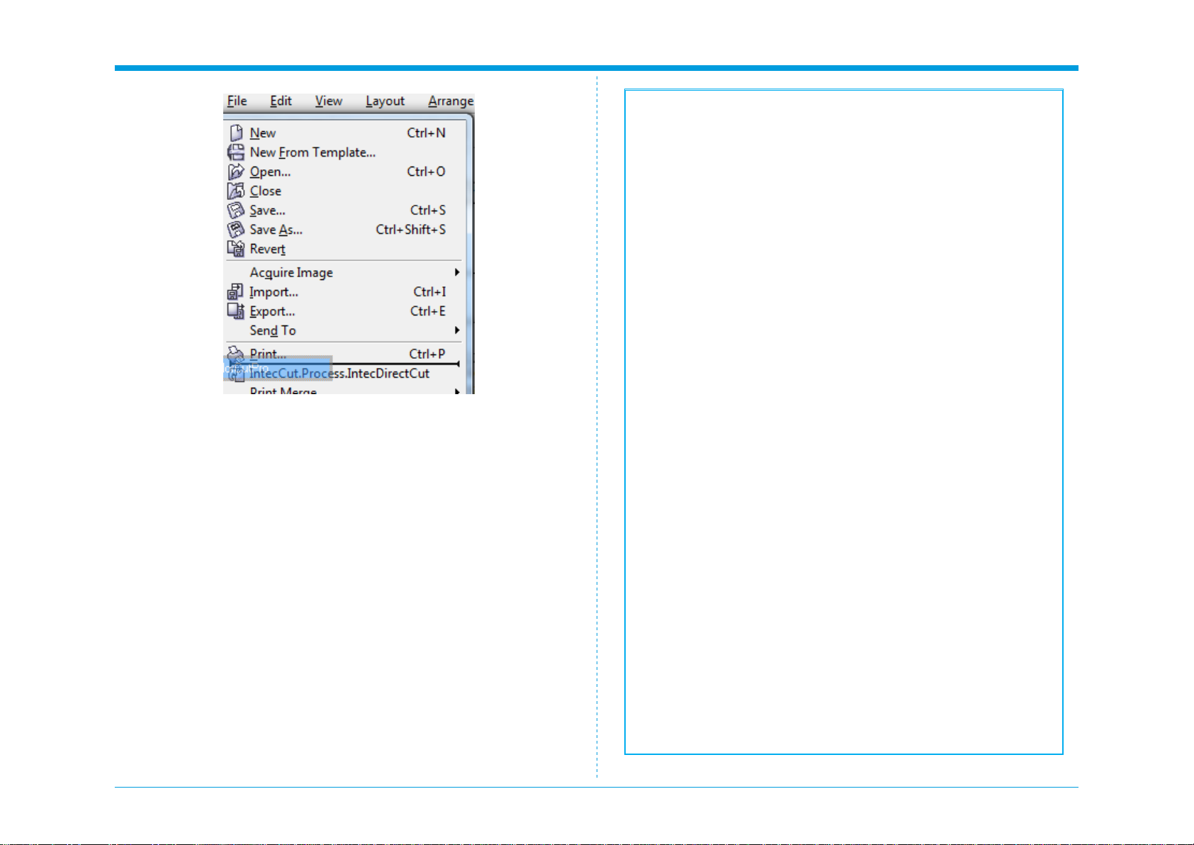
11.
To add the ColorCut Pro plug-in to your File Menu next to the Print item,
press and hold on the Command name again at point, Click and hold the
left mouse button and drag the icon until you position the mouse over
FileMenu,whichwillpopopentheledrop-downmenu.
12.
Then move the mouse to next to the print button without releasing it and
letgoofthemousebutton.YoushouldnowseetheColorCutPromenu
option appear.
Installation of CorelDRAW is now complete, continue on to the next section.
Intentionally blank
Table of contents
Other Intec Cutter manuals


Popular Cutter manuals by other brands


Huskie Tools
Huskie Tools S-16 Operating instructions manual

Tracmaster
Tracmaster CAMON TC12 OPERATING INSTRUCTIONS & SAFETY NOTES OPERATING INSTRUC

SPEWE
SPEWE 212SL-30 operating instructions

VEVOR
VEVOR k110D manual

Partner
Partner K950 RING Workshop manual

Alpha Professional Tools
Alpha Professional Tools AWS-110 instruction manual


