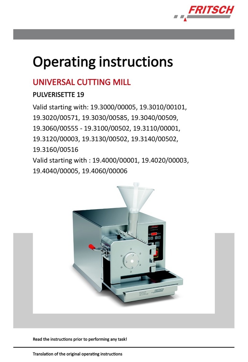
Fritsch PULVERISETTE 19 User manual

UNIVERSAL CUTTING MILL
PULVERISETTE 19
Operating instructions
Valid starting with: 19.10xx/0100
Read the instructions prior to performing any task!
Translation of the original operating instructions

Version 09/2014 Index 010
Fritsch GmbH
Milling and Sizing
Industriestraße 8
55743 Idar-Oberstein
Telephone: +49 (0)6784/ 70-0
Fax: +49 (0)6784/ 70-11
Email: [email protected]
Internet: www.fritsch.de

Certifications and CE conformity
Fritsch GmbH has been certified by the TÜV-Zertifizierungsgemeinschaft
e.V.
An audit certified that Fritsch GmbH conforms to the requirements of
the DIN EN ISO 9001:2008.
The enclosed Conformity Declaration lists the guidelines the FRITSCH
instrument conforms to, to be able to bear the CE mark.
Certification
CE Conformity
Certifications and CE conformity
- 3 -

Table of contents
1Basic structure............................................................................... 7
2 Safety information and use........................................................... 9
2.1 Requirements for the user..................................................... 9
2.2 Scope of application............................................................... 9
2.2.1 Operating principle........................................................... 10
2.3 Obligations of the operator................................................. 10
2.4 Information on hazards and symbols used in this manual.. 11
2.5 Device safety information.................................................... 13
2.6 Protective equipment.......................................................... 14
2.6.1 Opening the cutting mill without mains connection........ 15
2.7 Hazardous points................................................................. 15
2.8 Electrical safety.................................................................... 16
2.8.1 General information......................................................... 16
2.8.2 Protection against restart................................................. 17
2.8.3 Direction of rotation detection......................................... 17
2.8.4 Overload protection.......................................................... 17
3 Technical data.............................................................................. 18
3.1 Dimensions.......................................................................... 18
3.2 Weight.................................................................................. 18
3.3 Operating noise.................................................................... 18
3.4 Voltage................................................................................. 18
3.5 Current consumption........................................................... 18
3.6 Power consumption............................................................. 18
3.7 Motor shaft power in accordance with VDE 0530, EN
60034................................................................................... 19
3.8 Electrical fuses..................................................................... 19
3.9 Material................................................................................ 19
3.10 Final fineness..................................................................... 19
3.11 Speed................................................................................. 19
4 Installation................................................................................... 20
4.1 Transport............................................................................. 20
4.2 Unpacking............................................................................ 20
4.3 Setting up............................................................................. 20
4.4 Ambient conditions.............................................................. 20
4.5 Fastening the Universal Cutting Mill.................................... 21
4.6 Selecting and converting the funnels................................... 21
4.6.1 Selecting the funnel.......................................................... 21
4.6.2 Converting from standard funnel to protected funnel..... 22
4.6.3 Converting from protected funnel to standard funnel..... 23
4.7 Electrical connection............................................................ 24
Table of contents
- 4 -

5 Initial start-up.............................................................................. 25
5.1 Before switching on for the first time.................................. 25
5.2 Switching on......................................................................... 26
5.3 Function check..................................................................... 26
5.4 Switching off........................................................................ 27
6 Using the device........................................................................... 28
6.1 Preparing a comminution.................................................... 28
6.1.1 Opening the cutting mill................................................... 28
6.1.2 Inserting / changing the fixed knives................................ 29
6.1.2.1 Installation position of the fixed knives......................... 30
6.1.2.2 Installation position of the fixed knives with tungsten
carbide cutting edge...................................................... 30
6.1.3 Setting the gap width of the knives.................................. 31
6.1.4 Inserting / changing a rotor.............................................. 32
6.1.5 Inserting / changing a sieve cassette................................ 33
6.1.5.1 Selecting the sieve cassette........................................... 34
6.1.6 Closing the cutting mill..................................................... 34
6.1.7 Checking if the rotor is turning freely............................... 35
6.2 Comminution procedure with standard funnel................... 35
6.2.1 Using the plunger.............................................................. 36
6.3 Comminution procedure with the protected funnel........... 36
6.4 Overload of the cutting mill................................................. 37
6.5 Sample exhaust system with cyclone separator.................. 39
7 Cleaning........................................................................................ 42
7.1 Housing................................................................................ 42
7.2 Cutting chamber.................................................................. 42
7.3 Funnel.................................................................................. 43
7.3.1 Standard funnel................................................................ 43
7.3.2 Protected funnel............................................................... 44
7.3.2.1 Removing sample pusher............................................... 44
7.3.2.2 Removing the plunger.................................................... 45
7.4 Collecting vessel................................................................... 45
7.5 Sample exhaust system with cyclone separator.................. 46
7.6 Cleaning the filter foam mat................................................ 46
8 Maintenance................................................................................ 47
9Repairs......................................................................................... 52
9.1 Checklist for troubleshooting............................................... 52
10 Disposal........................................................................................ 54
11 Guarantee terms.......................................................................... 55
12 Exclusion of liability..................................................................... 57
13 Safety logbook............................................................................. 59
Table of contents
- 5 -

1 Basic structure
1 Standard funnel
2 Upper part of housing
3 Rotor
4 Fixed knife 1
5 Fixed knife 2
6 Closing lid
7 Sieve cassette
8 Collecting vessel
9 Fixed knife 2
10 Lower part of housing
11 Lock
12 U-profile
13 Latch clamp
14 Motor cover
15 Safety switch
15* Safety switch bracket
Basic structure
- 7 -

1 Standard funnel
14 Motor cover
18 Ventilation grid
19 Control switch
20 Mains plug
21 Funnel lid
22 Protected funnel
23 Plunger (protected funnel)
24 Sample pusher
26 Plunger (standard funnel)
34 Start button
35 Stop button
Basic structure
- 8 -

2 Safety information and use
2.1 Requirements for the user
This operating manual is intended for persons assigned with operating
and monitoring the Fritsch PULVERISETTE 19. The operating manual and
especially its safety instructions are to be observed by all persons
working on or with this device. In addition, the applicable rules and regu-
lations for accident prevention at the installation site are to be observed.
Always keep the operating manual at the installation site of the PULVERI-
SETTE 19.
People with health problems or under the influence of medication,
drugs, alcohol or exhaustion must not operate this device.
The PULVERISETTE 19 may only be operated by authorised persons and
serviced or repaired by trained specialists. All commissioning, mainte-
nance and repair work may only be carried out by technically qualified
personnel. Qualified personnel are persons who, because of their educa-
tion, experience and training as well as their knowledge of relevant
standards, regulations, accident prevention guidelines and operating
conditions, are authorised by those responsible for the safety of the
machine to carry out the required work and are able to recognize and
avoid possible hazards as defined for skilled workers in IEC 364.
In order to prevent hazards to users, follow the instructions in this
manual.
Malfunctions that impair the safety of persons, the PULVERISETTE 19 or
other material property must be rectified immediately. The following
information serves both the personal safety of operating personnel as
well as the safety of the products described and any devices connected
to them: All maintenance and repair work may only be performed by
technically qualified personnel.
This operating manual is not a complete technical description. Only the
details required for operation and maintaining usability are described.
Fritsch has prepared and reviewed this operating manual with the
greatest care. However, no guarantee is made for its completeness or
accuracy.
Subject to technical modifications.
2.2 Scope of application
The Universal Cutting Mill can be used for the fast comminution of soft,
medium-hard, brittle, tough and fibrous materials like:
Sheet rubber, plastics, refuse-derived fuel, dry meat, leather, wood, coal,
malt, paper/cardboard, peat, animal feed, pasta, tablets, leaves, pellets,
spices, fabric, straw, maize, bones, roots, tobacco...
Safety information and use
- 9 -

2.2.1 Operating principle
The material is fed through a funnel (example in image with standard
funnel) into the cutting chamber. There, rotating knives (3) in combina-
tion with fixed knives (4,5,9) cut the material. The fine ground material
falls through a sieve cassette (7) into the collecting vessel (8).
For fine comminution, the sample exhaust system can be used with
cyclone separator (optional accessory 45.5900.00).
2.3 Obligations of the operator
Before using the PULVERISETTE 19, this manual is to be carefully read
and understood. The use of the PULVERISETTE 19 requires technical
knowledge; only commercial use is permitted.
The operating personnel must be familiar with the content of the oper-
ating manual. For this reason, it is very important that these persons
actually receive the present operating manual. Ensure that the operating
manual is always near the device.
The PULVERISETTE 19 may exclusively be used within the scope of appli-
cations set down in this manual and within the framework of guidelines
put forth in this manual. In case of non-compliance or improper use, the
customer assumes full liability for the functional capability of the PUL-
VERISETTE 19 and for any damage or injury arising from failure to fulfil
this obligation.
By using the PULVERISETTE 19 the customer agrees with this and recog-
nizes that defects, malfunctions or errors cannot be completely
excluded. To prevent risk of damage to persons or property or of other
direct or indirect damage, resulting from this or other causes, the cus-
tomer must implement sufficient and comprehensive safety measures
for working with the PULVERISETTE 19.
Neither compliance with this manual nor the conditions and methods
used during installation, operation, use and maintenance of the PUL-
VERISETTE 19 can be monitored by Fritsch GmbH. Improper execution of
the installation can result in property damage and thus endanger per-
sons. Therefore, we assume absolutely no responsibility or liability for
loss, damage or costs that result from errors at installation, improper
operation or improper use or improper maintenance or are in any way
connected to these.
Safety information and use
- 10 -

The applicable accident prevention guidelines must be complied with.
Generally applicable legal and other obligatory regulations regarding
environmental protection must be observed.
2.4 Information on hazards and symbols used in this manual
Safety information in this manual is designated by symbols. Safety infor-
mation is introduced by keywords that express the extent of the hazard.
DANGER!
This symbol and keyword combination points out a directly
hazardous situation that can result in death or serious
injury if not avoided.
WARNING!
This symbol and keyword combination points out a possibly
hazardous situation that can result in death or serious
injury if not avoided.
CAUTION!
This symbol and keyword combination points out a possibly
hazardous situation that can result in slight or minor injury
if not avoided.
NOTICE!
This symbol and keyword combination points out a possibly
hazardous situation that can result in property damage if
not avoided.
To call attention to specific hazards, the following symbols are used in
the safety information:
DANGER!
This symbol and keyword combination points out a directly
hazardous situation due to electrical current. Ignoring infor-
mation with this designation will result in serious or fatal
injury.
Safety information
Special safety information
Safety information and use
- 11 -

DANGER!
This symbol and keyword combination designates contents
and instructions for proper use of the machine in explosive
areas or with explosive substances. Ignoring information
with this designation will result in serious or fatal injury.
DANGER!
This symbol and keyword combination designates contents
and instructions for proper use of the machine with com-
bustible substances. Ignoring information with this designa-
tion will result in serious or fatal injury.
WARNING!
This symbol and keyword combination points out a directly
hazardous situation due to movable parts. Ignoring infor-
mation with this designation can result in hand injuries.
WARNING!
This symbol and keyword combination points out a directly
hazardous situation due to hot surfaces. Ignoring informa-
tion with this designation can result in serious burn injuries
due to skin contact with hot surfaces.
Safety information can refer to specific, individual procedure instruc-
tions. Such safety information is embedded in the procedure instructions
so that the text can be read without interruption as the procedure is
being carried out. The keywords described above are used.
Example:
1. Loosen screw.
2.
CAUTION!
Risk of entrapment at the lid.
Close the lid carefully.
3. Tighten screw.
Safety information in the procedure
instructions
Safety information and use
- 12 -

This symbol emphasises useful tips and recommendations
as wells as information for efficient operation without mal‐
function.
To emphasise procedure instructions, results, lists, references and other
elements, the following designations are used in this manual:
Designation Explanation
1., 2., 3. ...
Step-by-step procedure instructions
ðResults of steps in the procedure
References to sections in this manual and rele-
vant documentation
Lists without a specific order
[Button] Operating elements (e.g. push button, switch),
display elements (e.g. signal lamps)
‘Display’ Screen elements (e.g. buttons, function key
assignment)
2.5 Device safety information
nOnly use original accessories and original spare parts. Failure to
observe this instruction can compromise the safety of the machine.
nAccident-proof conduct is to be strictly followed during all work.
nComply with all currently applicable national and international acci-
dent prevention guidelines.
CAUTION!
Wear hearing protection!
If a noise level of 85 dB(A) is reached or exceeded, ear pro-
tection should be worn to prevent hearing damage.
WARNING!
The maximum accepted concentration (MAC) levels of the
relevant safety guidelines must be observed; if necessary,
ventilation must be provided or the machine must be oper-
ated under an extractor hood.
Tips and recommendations
Further designations
Please observe!
Safety information and use
- 13 -

DANGER!
Explosion hazard!
– When Comminution oxidizable substances, e.g. metals
or coal, there is a risk of spontaneous combustion (dust
explosion) if the share of fine particles exceeds a cer-
tain percentage. When Comminution these kinds of
substances, special safety measures must be taken and
the work must be supervised from a specialist.
–The PULVERISETTE 19 is not explosion protected and is
not designed to comminute explosive materials.
nDo not remove the information signs.
NOTICE!
Immediately replace damaged or illegible information signs.
nUnauthorised alteration of the PULVERISETTE 19 will void Fritsch's
declaration of conformity to European directives and void the guar-
antee.
nOnly use the PULVERISETTE 19 when it is in proper working order, as
intended and in a safety- and hazard-conscious manner adhering to
the operating manual. In particular, immediately rectify any malfunc-
tions that could pose a safety hazard.
nIf, after reading the operating manual, there are still questions or
problems, please do not hesitate to contact our specialised per-
sonnel.
2.6 Protective equipment
nProtective equipment is to be used as intended and may not be disa-
bled or removed.
nAll protective equipment is to be regularly checked for integrity and
proper functioning.
nThe Universal Cutting Mill is equipped with a safety lock (11) which
also protects the operator. This locks the front closing lid (6) during
operation.
nThe safety switches (11, 15) prevent operation of the Universal Cut-
ting Mill, if the cutting chamber is not closed or a collecting vessel (8)
has not been inserted.
nDo not operate the device without a funnel (1 or 22)!
Funnels (1, 22) are mechanical safety devices that enable hazard-
free filling.
nWhen changing the funnels (1, 22), disconnect the device from the
mains and install the new funnel (1, 22) immediately! (
Ä
‘Selecting
and converting the funnels’ on page 21)
nMotor safety switch (
Ä
‘Overload of the cutting mill’ on page 37)
Safety information and use
- 14 -

2.6.1 Opening the cutting mill without mains connection
DANGER!
The lock must only be released manually when the closing
lid is closed.
The latch clamp of the door must be locked!
1. Insert the supplied triangular key into the bore hole under the
safety lock (11) and turn it clockwise.
2. The closing lid (6) can be opened after opening the latch clamp
(13).
3. At this time, it is not possible to switch on the Universal Cutting
Mill. To switch it on, the safety lock (11) must be activated by
turning the triangular key to the left, the closing lid (6) must be
closed and the latch clamp (13) in locked position.
2.7 Hazardous points
nThe closing lid (6) can be lifted out of the hinges. When opening the
upper part of the housing (2) it is possible to leave the closing lid (6)
in the hinge. If this is the case, ensure that the closing lid (6) does
not lift out of the hinge when opening the upper part of the housing
(2).
Safety information and use
- 15 -

nWhen opening the upper part of the housing (2), there is an initial
resistance.
nMake sure that the closing lid (6) is fully open!
nWhen opening the upper part of the housing (2), slowly swivel it
open until the upper part of the housing (2) is resting on the rubber
buffer - do not let it fall down heavily.
nCrushing hazard when closing the upper part of the housing (2).
Close it slowly!
nAfter checking if the rotor (3) is turning freely (
Ä
‘Checking if the
rotor is turning freely’ on page 35), the required hexagon socket
screw key must be removed immediately.
2.8 Electrical safety
2.8.1 General information
nThe switch (19) on the back is not a main switch but rather a control
switch. Therefore the mains plug (20) must be plugged out in order
to safely disconnect the supply voltage.
nSwitch the control switch (19) on the back of the Universal Cutting
Mill to 0, if the device is to be idle for a longer period of time (e.g.
overnight).
Safety information and use
- 16 -

2.8.2 Protection against restart
In the case of power failure during operation or after switching off with
the control switch (19), the closing lid (6) is locked. The lock (11) is
opened when power returns. However, for safety reasons the cutting
mill does not restart.
2.8.3 Direction of rotation detection
A unit for detection of the direction of rotation is installed in devices
with a three-phase motor:
If the STOP button (35) lights up red after connecting to a three-phase
power system and switching the control switch (19) to AUTO, the direc-
tion of rotation must be corrected. To do this, two phases in the mains
plug must be reversed.
Ä
‘Electrical connection’ on page 24.
2.8.4 Overload protection
nThe motor protection switch switches off if overload occurs.
Ä
‘Overload of the cutting mill’ on page 37. The STOP button lights
up red.
Safety information and use
- 17 -

3 Technical data
3.1 Dimensions
440 mm x 550 mm x 630 mm
(width x depth x height)
3.2 Weight
n56 - 65 kg (net)
n86 - 95 kg (gross)
3.3 Operating noise
The noise level is approx. 78 dB (A) when idle and 95 dB (A) when idle
incl. cyclone separator. The value fluctuates strongly depending on the
comminution material.
3.4 Voltage
n400V / 3~
n230V / 1~
n100-120V / 1~
3.5 Current consumption
n16A for 400V / 3~ motor
n16A for 230V / 1~ motor
n15A for 100-120V / 1~ motor
(
Ä
‘Electrical connection’ on page 24)
Transient overvoltage according to overvoltage category II is per-
mitted.
3.6 Power consumption
n3240 W for 400V / 3~ motor
n2000 W for 400V / 3~ motor
n2200 W for 230V / 1~ motor
n1850 W for 100-120V / 1~ motor
Technical data
- 18 -

3.7 Motor shaft power in accordance with VDE 0530, EN 60034
n2.2 kW for 400V / 3~ motor
n1.5 kW for 400V / 3~ motor
n1.5 kW for 230V / 1~ motor
n1.1 kW for 100-120V / 1~ motor
3.8 Electrical fuses
nCircuit breaker in device
nMicro-fuse in device
nMotor safety switch (
Ä
‘Overload of the cutting mill’ on page 37)
nDirection of rotation detection in three-phase model (
Ä
‘Electrical
safety’ on page 16)
3.9 Material
Depending on material and funnel (1, 22) up to 70 x 80 mm. Harder
material max. 10 mm.
Batchwise feeding!
Throughput
Depending on material property and sieve used, up to 60 l/h.
3.10 Final fineness
Achievable average final fineness depending on sieve insert, 0.2 - 6 mm.
3.11 Speed
50 Hz 60 Hz Order No.:
302 - 1168 rpm/min 19.108x.00
2800 - 3400 rpm/min 19.10x0.00
Feed size
Technical data
- 19 -

4 Installation
4.1 Transport
nTransport on transport palette with a forklift or pallet truck.
nWhen lifting the device hold it underneath at the back and front
only. Do not lift it using the plastic cover.
CAUTION!
When lifting off, at least 2 persons are required!
4.2 Unpacking
nPull out the nails that fasten the crate to the transport pallet.
nLift the crate off the transport pallet.
nCompare the contents of the delivery with your order.
4.3 Setting up
n4 screws connect the cutting mill to the transport pallet.
Remove the 4 screws.
nLift the cutting mill off the transport pallet.
CAUTION!
When lifting off, at least 2 persons are required!
4.4 Ambient conditions
nThe device may only be operated indoors.
nThe surrounding air may not carry any electrically conductive dust.
nThe room temperature should be between 5 and 40 °C.
nAltitudes up to 2000 m NN.
nMaximum relative humidity 80% for temperatures up to 31 °C, line-
arly decreasing down to 50% relative humidity at 40 °C.
nDegree of pollution 2 according to IEC 664.
Installation
- 20 -
Other manuals for PULVERISETTE 19
2
Table of contents
Other Fritsch Cutter manuals
Popular Cutter manuals by other brands

Craftsman
Craftsman CompuCarve 133.217540 Operator's manual

Carpenter MFG. Co., Inc.
Carpenter MFG. Co., Inc. Compu-Strip 93 Operator's manual

Sunrise Electronic Technology
Sunrise Electronic Technology Skycut Series C with SignMaster manual

Holmatro
Holmatro PCU50 manual

WOLFF
WOLFF WO 330 Translation of the original instruction

Makita
Makita CP100D instruction manual

WOLFF
WOLFF Linocut manual

Hypertherm
Hypertherm HyPerformance Plasma HPR400 instruction manual

Ingersoll-Rand
Ingersoll-Rand 326 Operation and maintenance manual

Baileigh Industrial
Baileigh Industrial TN-800 Operator's manual

Ellison
Ellison AllStar Instructions for use

Jenlis
Jenlis Weed Razer Pro product manual