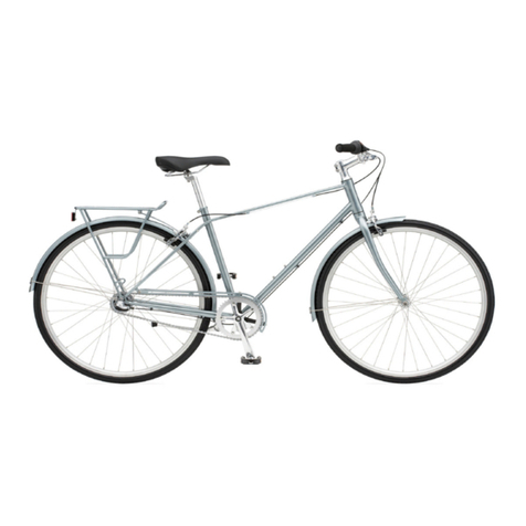
Bobbin Daytripper User manual

How to assemble your Adult bike
1"

Introduction
A ‘New bike day’ is always a good day.
Congratulations on your new Bobbin bike.
Here’s our step by step guide to assembling your new
Bobbin. Allow 30-60 minutes to put your bike
together and have it ready to ride.
Happy Cycling!
2"
Pages
3. List of Tools
4. Unpacking
6. Fitting Mudguard
9. Attaching Front Wheel
11. Handlebar
13. Kickstand
14. Saddle
17. Pedals
18. Bell
19. Reflectors
20. Brakes
24. Gears
26. Check List
27. Maintenance

Tools
You will need a few tools for the job:
• 4mm, 5mm and 6mm Allen keys
• 15mm and two 10mm spanners
• Phillips screwdriver
• Scissors
• Pump
• Bike grease
3"

UNPACKING
• Stand the bike box upright in a well-lit space big
enough for you to work in, and with a flat surface
handy for placing tools and parts
• Using the scissors remove and discard all the
large staples from the top (this will prevent them
scratching either you or the paintwork
as you remove the bike)
• Open the top of the box and pull the bike out.
The bike will look something like this picture.
• Place the bike on the floor between you and the
box with the bike standing on its rear wheel and
front forks, chain side closest to you
4"

UNPACKING (continued)
• Taking care not to scratch the paintwork,
remove all the packaging and put it in the
empty box. Check the packaging first for any
small parts
• Turn the forks the right way around
(front brake points forwards), your bike now
looks something like this:
5"

FRONT MUDGUARD FITTING
If your Bobbin has a 10mm nut behind the fork:
• Unfasten the nut, then fasten the mudguard tab
behind the fork like this. Use a 10mm spanner
• Some of our bikes don’t have brakes attached to the fork.
A bolt goes straight through. You’ll need another 10mm
spanner to hold this bolt at the front while you tighten it at
the back
6"

FRONT MUDGUARD FITTING (continued)
If your Bobbin has a 5mm recessed Allen bolt:
• Use a 5mm Allen key, unfasten the bolt,
then fasten the mudguard tab in front of the
fork like this
7"

FRONT MUDGUARD FITTING (continued)
The next step is to attach the mudguard arms
to the forks
• First, remove the bolts/nuts that are already
attached at the bottom of each fork blade.
Use either a 10mm or 8mm spanner, or an
allen key
• Now attach the mudguard arms securely
on each side
8"

FRONT WHEEL FITTING
• Check which way round the wheel should go.
• There’s either a rotating direction indicated on the tyre
sidewall or the tread shape indicates the direction.
9"

FRONT WHEEL FITTING (continued)
• Loosely fit the washers and domed wheel nuts to the front
axle (if the washers are tabbed washers these point
inwards)
• Keeping the washers and wheel nuts on the outside of the
fork legs, lower the fork onto the wheel. (It’s easier to lower
the fork onto the axle from above than the other way
around)
1.
2.
Important! If you have tabbed
washers put the tab into the hole in
the fork. Check the wheel is sitting
centrally in the fork before securely
fastening the wheel nuts with the
15mm spanner.
10"

QUILL STEM AND HANDLEBAR FITTING
• Remove and discard the plastic cap (if there is one) from the
bottom of stem
• Remove and keep the little plastic plug (if there is one) from
the head of the stem top bolt
11"

• Insert the stem into the hole in the headset (A).
The ‘minimum insertion line’ is marked on the
stem. Use your allen key to tighten the bolt (B),
located at the top.
• Align the handlebars in the stem (choose your
angle - horizontal best). Use your allen key to
tighten, very securely, the clamp bolt (C) located
at the front of the stem.
• Stand over the bike as though you are riding.
Check the bars are completely in line with the
front wheel. Now tighten, very securely, bolt (B).
• IMPORTANT! Is everything tight? Press down
on the bars from the top. Now then stand with
the front wheel between your legs and try to
twist the bars. Nothing should move.
• Replace the plastic plug in top of stem bolt
A
B
C
12"
QUILL STEM AND HANDLEBAR FITTING (continued)

KICKSTAND ADJUSTMENT
(skip this page if your bike doesn’t have a kickstand)
• Flip down the kickstand. If your kickstand has an
adjuster screw you can adjust this with a Phillips
screwdriver. In the correct position your bike is properly
supported and leaning a little to the left
13"

SADDLE AND SEATPOST FITTING
If your saddle and seat post are separate:
• Loosen the seatbolt (F) and rotate the top half of the
clamp 90 degrees to allow it to fit the saddle
• With the saddle rails sat on the lower clamp, rotate the
top half of the clamp back to it’s original position and
fasten the seatbolt very tightly (F)
• Grease the post a little to prevent it getting stuck
in the frame F
14"

SADDLE AND SEATPOST FITTING (continued)
• Insert the seat post (G) into the frame.
• Tighten the seat collar (H).
• Note the ‘minimum insertion mark’ printed on the seat
post.
Setting up your saddle:
• Aim to be standing on tip-toes when you are sitting on
the saddle. Lower = harder to ride!
• Check the saddle is level and pointing forwards
• You can slide the saddle forwards and backwards on
the rail, and adjust the angle to suit you. Everyone is
different!
• IMPORTANT! As with all your adjustments, check all
bolts are secure and tight before riding
G
H
15"

SADDLE AND SEATPOST FITTING (quick release seat
post clamp)
• Open up the quick release seat post clamp.
• Insert the seat post into the frame.
• Note the ‘minimum insertion mark’ printed on the seat
post.
Setting up your saddle:
• Aim to be standing on tip-toes when you are sitting on
the saddle. Lower = harder to ride!
• Check the saddle is level and pointing forwards
• You can slide the saddle forwards and backwards on
the rail, and adjust the angle to suit you. Everyone is
different!
• IMPORTANT! As with all your adjustments, check all
bolts are secure and tight before riding
G
16"

PEDAL FITTING
• IMPORTANT! Left and Right pedals are NOT the same.
Force-tting the wrong one will break your crank.
• The pedals have different thread directions to ensure they
remain tight during use. They are marked L and R for left
and right, either with a sticker or with a marking on the end
of the pedal axle
• Apply some grease to the thread of each pedal
• Fit the pedal marked R to the right hand crank arm with
your fingers and turn gently in a clockwise direction. Once
it ‘bites’ tighten securely with a 15mm wrench or pedal
spanner
• Fit the pedal marked L to the left hand crank arm with your
fingers and turn gently in an anti-clockwise direction.
Once it ‘bites’ tighten securely with a 15mm wrench or
pedal spanner
• The pedals should attach smoothly; if not stop and check
the pedals are on the correct side and are screwing in
straight not at an angle
Left
Right
17"

BELL FITTING
• The bell goes on the left hand side of the
handlebars (so it’s within easy reach of your
thumb when you’ve got your hands on the
grips)
• The bell is fitted with the Philips screwdriver
18"

REFLECTOR FITTING
• If your bike doesn’t have a painted rear rack (which
includes a reflector) it will have a red
rear reflector which fits to the sea tpost using
the Philips Screwdriver
• The white front reflector will either fit on the handlebar
or mount behind the brake caliper depending on your
bike model
19"

BRAKE ADJUSTMENT V-BRAKES
(skip this step if you don’t have V-brakes)
• Lift the wheel and spin it, it shouldn’t make any noise or
drag against the pads
• If noisy, first check the wheel is correctly installed in the
middle of the forks.
• If it is, you may need to centre the brake (if one side of
the brake is closer to the wheel than the other side).
• Adjust the v-brakes by using a Phillips (cross head)
screwdriver on the spring adjuster screw (G)
• Clockwise (tightening) moves the pad away from the
wheel rim. Anti-clockwise (loosening) moves the pad
towards the wheel rim.
• Keep squeezing the brake lever to check your
adjustments.
• NOTE: also check your pads are straight and not
touching the tires. You can adjust here (H)."
20"
G
H
This manual suits for next models
1
Table of contents
Other Bobbin Bicycle manuals

