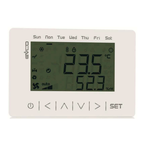
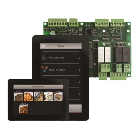
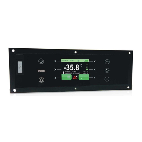
Evco C-PRO MEGA Instructions for use

PROGRAMMABLE CONTROLLERS FOR
SINGLE CIRCUIT, DUAL CIRCUIT AND
TRIPLE CIRCUIT
COMPRESSOR PACKS
UP TO 8/12 COMPRESSORS
APPLICATION MANUAL
CODE 144RACKMGE04

C-PRO MEGA RACK & C-PRO GIGA RACK APPLICATION MANUAL
Page
2
Important
Please read these instructions carefully prior to installation and use, and follow all the precautions for installation and
electrical connections; keep these instructions with the device for future consultation.
The device must be disposed of in accordance with local regulations pertaining to the collection of electrical and
electronic appliances.

C-PRO MEGA RACK & C-PRO GIGA RACK APPLICATION MANUAL
Page
3
Table of contents
1
GENERAL INFORMATION......................................................................................................5
1.1
Description ............................................................................................................................5
2
APPLICATIONS.........................................................................................................................8
2.1
Application 1: use of the C-PRO MEGA RACK (single circuit control unit)......................9
2.2
Application 2: use of the C-PRO GIGA RACK (dual circuit control unit with separate
condensation).................................................................................................................................10
2.3
Application 3: use of the C-PRO MEGA RACK with the C-PRO EXP MEGA I/O
expansion unit (dual circuit control unit with separate condensation)...........................................11
2.4
Application 4: use of the C-PRO GIGA RACK with the C-PRO EXP GIGA I/O expansion
unit (dual circuit control unit with separate condensation)............................................................12
2.5
Controller electrical connections.........................................................................................13
2.5.1
C-PRO MEGA RACK electrical connections .............................................................13
2.5.2
C-PRO GIGA RACK electrical connections...............................................................14
2.5.3
Input and output identification tables...........................................................................15
2.6
Preset configurations...........................................................................................................19
2.6.1
C-PRO MEGA RACK preset configurations (single circuit compressor packs) ........19
2.6.2
C-PRO GIGA RACK preset configurations (dual circuit compressor packs).............20
2.7
I/O expansion unit electrical connections ...........................................................................21
2.7.1
C-PRO EXP MEGA electrical connections.................................................................21
2.7.2
C-PRO EXP GIGA electrical connections...................................................................22
2.7.3
Input and output identification tables...........................................................................23
3
COMPONENT NETWORK AND ACCESSORIES ................................................................26
3.1
Example for the C-PRO MEGA RACK and C-PRO GIGA RACK built-in versions........26
3.2
Example for the C-PRO MEGA RACK and C-PRO GIGA RACK case versions Errore. Il
segnalibro non è definito.
4
USER INTERFACE ..................................................................................................................27
4.1
Display and keypad.............................................................................................................27
4.1.1
Built-in interface ................................................. Errore. Il segnalibro non è definito.
4.1.2
V- View user terminal......................................... Errore. Il segnalibro non è definito.
4.2
Page list ...............................................................................................................................28
4.3
Conditioned visibility..........................................................................................................34
5
CONFIGURATION PARAMETERS .......................................................................................35
6
REGULATIONS........................................................................................................................68
6.1
Machine configuration ........................................................................................................68
6.2
Machine and individual circuit status..................................................................................69
6.3
Compressor regulation ........................................................................................................71
6.3.1
Side band regulation.....................................................................................................71
6.3.2
Neutral zone regulation................................................................................................72
6.3.3
Side band regulation with inverter...............................................................................73
6.3.4
Neutral zone regulation with inverter ..........................................................................74
6.4
Compressor management ....................................................................................................75
6.4.1
Compressors per circuit ...............................................................................................76
6.4.2
Compressor status........................................................................................................76
6.4.3
Compressor rotation.....................................................................................................77
6.4.4
Increment management................................................................................................78
6.4.5
Protective device timings.............................................................................................80
6.4.6
Startup delay from reset...............................................................................................81
6.4.7
Safety device inputs .....................................................................................................81
C-PRO MEGA RACK & C-PRO GIGA RACK APPLICATION MANUAL
Page
4
6.4.8
Inverter configuration ..................................................................................................82
6.4.9
Compressors of different nominal power.....................................................................83
6.4.10
Suction line loss of load compensation........................................................................84
6.4.11
Refrigeration power incrementing at high pressures ...................................................85
6.5
Condensation regulation......................................................................................................86
6.5.1
Side band regulation.....................................................................................................86
6.5.2
Neutral zone regulation................................................................................................86
6.5.3
Side band regulation with inverter...............................................................................87
6.5.4
Neutral zone regulation with inverter ..........................................................................88
6.5.5
Unique condensation (dual/triple circuits only)...........................................................89
6.6
Fan management..................................................................................................................90
6.6.1
Fans per circuit.............................................................................................................90
6.6.2
Fan status......................................................................................................................90
6.6.3
Fan rotation..................................................................................................................91
6.6.4
Protective device timings.............................................................................................92
6.6.5
Safety device inputs .....................................................................................................93
6.6.6
Inverter configuration ..................................................................................................93
6.7
Miscellaneous controls........................................................................................................94
6.7.1
Inverter configuration (compressors/fans)...................................................................94
6.7.2
Compressor time bands................................................................................................95
6.7.3
Fan time bands.............................................................................................................96
6.7.4
Digital input setpoint alteration....................................................................................97
6.7.5
Supervisor setpoint alteration.......................................................................................97
6.7.6
Manual operation .........................................................................................................97
6.7.7
Floating condensation management.............................................................................98
6.7.8
Temperature probes......................................................................................................99
6.7.9
Last maintenance date..................................................................................................99
6.7.10
Restore default parameters...........................................................................................99
7
DIAGNOSTICS.......................................................................................................................100
7.1
Manual and automatic alarms............................................................................................100
7.1.1
Manual alarms............................................................................................................100
7.1.2
Automatic alarms.......................................................................................................101
7.2
Alarm table........................................................................................................................101
7.3
Alarm relays......................................................................................................................104
8
LIST OF MODBUS VARIABLES..........................................................................................106
8.1.1
Modbus export table (C-PRO GIGA)........................................................................106
8.1.2
Modbus export table (C-PRO MEGA) ......................................................................122

C-PRO MEGA RACK & C-PRO GIGA RACK APPLICATION MANUAL
Page
5
1GENERAL INFORMATION
1.1 Description
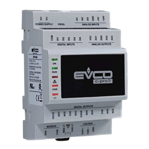
This application uses C-PRO MEGA and C-PRO GIGA controllers to manage a compressor packs
composed of one, two or three circuits with a maximum number of 8 compressors (if using C-PRO
MEGA controllers) or 12 compressors (if using C-PRO GIGA controllers).
A compressor packs control system is required to manage the compressors in order to maintain the
evaporation pressure at the desired value; more specifically, it must guarantee the production of
cold, for example for the preservation of foodstuffs.
Continuous generation of cold is required for this, using a process which must continue without any
interruptions, except for normal maintenance operations.
The C-PRO MEGA and C-PRO GIGA controllers are dedicated to this process, managing all the
components of the refrigeration circuit, maintaining the required conditions with the greatest
possible efficiency (greater output = lower running costs), with optimal handling of mechanical
components in order to reduce breakdowns (for example, fewer start-ups = less mechanical stress).
Two types of regulation may be selected for controlling pressure or temperature:
⋅Side Band
⋅Neutral Zone
Safety devices are managed for each circuit so as to promptly detect any malfunctions. Each safety
device is associated with a particular alarm, which will be triggered in order to identify the type of
fault. The outcome of certain alarms will be to shutdown the relevant mechanical devices, in order
to avoid further faults; others will only indicate the fault, without having any effect on the operation
of the machine.
The application has a navigable user interface, by means of which it is possible to define and set all
configuration and operational parameters. The user interface is subdivided into four main levels:
⋅User
⋅Service
⋅Installer
⋅System builder
Each level is protected by a separate password. At the system builder level, the user interface
displays a series of modifiable configuration screens (wizards) allowing easy setting of the number
of circuits, compressors, fans and the corresponding safety devices used for the protection of the
mechanical devices. There are also several free-access pages, not password protected, for checking
the operational status of the system at that particular time.
In addition to the aforementioned four levels, there is also a Clock menu (for setting the parameters
associated with the system RTC, such as for example those related to management of the time
bands for variation of the setpoints).
The versions have an integrated 4 x 20 character alphanumeric display, keypad and warning LEDs.
Each version has an optoisolated RS-485 port (for connection to the RICS or other BMS
supervision system) and a non-optoisolated CAN port (for connection to I/O expansion unit).

C-PRO MEGA RACK & C-PRO GIGA RACK APPLICATION MANUAL
Page
6
C-PRO MEGA

C-PRO MEGA RACK & C-PRO GIGA RACK APPLICATION MANUAL
Page
7
C-PRO GIGA

C-PRO MEGA RACK & C-PRO GIGA RACK APPLICATION MANUAL
Page
8
2APPLICATIONS
Using the CAN protocol, it is possible to connect an 8 relay (C-PRO EXP MEGA) or 13 relay
(C-PRO EXP GIGA) expansion module to the controllers.
Management of four different types of control unit is envisaged:
1) Application 1: C-PRO MEGA RACK (for single circuit control units; C-PRO MEGA
RACK preset configuration)
Total No. of digital outputs = 8
Total No. of digital inputs = 10
Total No. of analogue inputs = 8
Total No. of analogue outputs = 4
2) Application 2: C-PRO GIGA RACK (for dual circuit control units; preset
configuration)
Total No. of digital outputs = 13
Total No. of digital inputs = 12
Total No. of analogue inputs = 8
Total No. of analogue outputs = 4
3) Application 3: C-PRO MEGA RACK + C-PRO EXP MEGA (e.g. for dual circuit
control units)
Total No. of digital outputs = 8 + 8 = 16
Total No. of digital inputs = 10 + 8 = 18
Total No. of analogue inputs = 8 +4 = 12
Total No. of analogue outputs = 4
4) Application 4: C-PRO GIGA RACK + C-PRO EXP GIGA (e.g. for dual circuit control
units)
5) Total No. of digital outputs = 13 +13 = 26
Total No. of digital inputs = 12 +10 = 22
Total No. of analogue inputs = 8 +4 = 12
Total No. of analogue outputs = 4

C-PRO MEGA RACK & C-PRO GIGA RACK APPLICATION MANUAL
Page
9
2.1 Application 1: use of the C-PRO MEGA RACK (single circuit
control unit)
As a preset configuration, the C-PRO MEGA RACK is configured to manage single circuit
compressor packs; the services mentioned in the figure below refer specifically to the preset
configurations.

C-PRO MEGA RACK & C-PRO GIGA RACK APPLICATION MANUAL
Page
10
2.2 Application 2: use of the C-PRO GIGA RACK (dual circuit
control unit with separate condensation)
The C-PRO GIGA RACK is pre-configured to control dual circuit compressor packs; the services
mentioned in the figure below refer precisely to the preset configurations.
Compressors 1 and 2 (and related load increments) appertain to circuit 1; compressors 3 and 4 (and
related load increments) appertain to circuit 2.
Fans 1 and 2 appertain to circuit 1; fans 3 and 4 appertain to circuit 2.

C-PRO MEGA RACK & C-PRO GIGA RACK APPLICATION MANUAL
Page
11
2.3 Application 3: use of the C-PRO MEGA RACK with the C-PRO
EXP MEGA I/O expansion unit (dual circuit control unit with
separate condensation)
The C-PRO MEGA RACK is pre-configured to control single circuit compressor packs; the
services mentioned in the figure below refer to an example of a dual circuit control unit with
separate condensation.
Compressors 1, 2 and 3 appertain to circuit 1; compressors 4, 5 and 6 appertain to circuit 2.
Fans 1, 2 and 3 appertain to circuit 1; fans 4, 5 and 6 appertain to circuit 2.
The C-PRO MEGA RACK and C-PRO EXP MEGA power supplies must be galvanically
isolated from one another.

C-PRO MEGA RACK & C-PRO GIGA RACK APPLICATION MANUAL
Page
12
2.4 Application 4: use of the C-PRO GIGA RACK with the C-PRO
EXP GIGA I/O expansion unit (dual circuit control unit with
separate condensation)
The C-PRO GIGA RACK is factory pre-configured to control dual circuit compressor packs; the
services mentioned in the figure below refer to an example of a dual circuit control unit with
separate condenser, where the controller is used with an I/O expansion unit.
Compressors 1, 2 and 3 appertain to circuit 1; compressors 4, 5 and 6 appertain to circuit 2.
Fans 1, 2 and 3 appertain to circuit 1; fans 4, 5 and 6 appertain to circuit 2.
The C-PRO GIGA RACK and C-PRO EXP GIGA power supplies must be galvanically
isolated from one another.

C-PRO MEGA RACK & C-PRO GIGA RACK APPLICATION MANUAL
Page
13
2.5 Controller electrical connections
The layout relating to the controllers electrical connections is shown below, with tables listing the
meanings of the inputs and outputs.
2.5.1 C-PRO MEGA RACK electrical connections

C-PRO MEGA RACK & C-PRO GIGA RACK APPLICATION MANUAL
Page
14
2.5.2 C-PRO GIGA RACK electrical connections

C-PRO MEGA RACK & C-PRO GIGA RACK APPLICATION MANUAL
Page
15
2.5.3 Input and output identification tables
Card with 12 VDC + 12 VDC dual power supplies
Conn.
Abbre
v.
Description
C1-1
VCC main card power supply input (+13 VDC)
C1-2
GND main power supply reference
JA-1 VDC active probe power supply (*1)
JA-2 AI 1 No.1 universal analogue input (NTC, PTC, 0..5V, 0..10V, 0..20 mA, 4..20 mA)
JA-3 GND analogue input common ground
JB-1
VDC active probe power supply (*1)
JB-2 AI 2 No.2 universal analogue input (NTC, PTC, 0..5V, 0..10V, 0..20 mA, 4..20 mA)
JB-3 GND analogue input common ground
JC-1 VDC active probe power supply (*1)
JC-2 AI 3 No.3 configurable analogue input (NTC, 0..20 mA, 4..20 mA)
JC-3 AI 4 No.4 configurable analogue input (NTC, 0..20 mA, 4..20 mA)
JC-4 GND analogue input common ground
JD-1 VDC active probe power supply (*1)
JD-2 AI 5 No.5 configurable analogue input (NTC, 0..20 mA, 4..20 mA)
JD-3 AI 6 No.6 configurable analogue input (NTC, 0..20 mA, 4..20 mA)
JD-4 AI 7 No.7 configurable analogue input (NTC, 0..20 mA, 4..20 mA)
JD-5 AI 8 No.8 configurable analogue input (NTC, 0..20 mA, 4..20 mA)
JD-6 GND analogue input common ground
JE-1 COM digital input common connection
JE-2
DI 1 No.1 digital input 12-24 VAC/DC
JE-3
DI 2
No.2 digital input 12-24 VAC/DC
JE-4 COM digital input common connection
JF-1 COM digital input common connection
JF-2 DI 3 No.3 digital input 12-24 VAC/DC
JF-3 DI 4 No.4 digital input 12-24 VAC/DC
JF-4 DI 5 No.5 digital input 12-24 VAC/DC
JF-5 DI 6 No.6 digital input 12-24 VAC/DC
JF-6 COM digital input common connection
JG-1 COM digital input common connection
JG-2 DI 7 No.7 digital input 12-24 VAC/DC
JG-3 DI 8 No.8 digital input 12-24 VAC/DC
JG-4 DI 9 No.9 digital input 12-24 VAC/DC
JG-5 DI 10 No.10 digital input 12-24 VAC/DC
JG-6 COM digital input common connection
YA-1 VDC power supply output connector (12 VDC)
YA-2 CAN1+
connector for connecting the LOCAL CAN serial port (CAN+)
YA-3
CAN1- connector for connecting the LOCAL CAN serial port (CAN-)
YA-4 GND power supply reference output connector (ground)
JH-1
NC 1 relay No. 1 contact normally closed
JH-2
COM 1 relay No. 1 common connection
JH-3
NO 1
relay No. 1 contact normally open
JI-1 NC 2 relay No. 2 contact normally closed
JI-2 COM 2 relay No. 2 common connection
JI-3 NO 2 relay No. 2 contact normally open
JK-1 COM 3 relay No. 3 common connection
JK-2 NO 3 relay No. 3 contact normally open

C-PRO MEGA RACK & C-PRO GIGA RACK APPLICATION MANUAL
Page
16
Conn.
Abbre
v.
Description
JK-3 COM 4 relay No. 4 common connection
JK-4 NO 4 relay No. 4 contact normally open
JK-5 COM 5 relay No. 5 common connection
JK-6 NO 5 relay No. 5 contact normally open
JL-1 COM 6 relay No. 6 common connection
JL-2 NO 6 relay No. 6 contact normally open
JL-3 COM 7 relay No. 7 common connection
JL-4 NO 7 relay No. 7 contact normally open
JL-5 COM 8 relay No. 8 common connection
JL-6 NO 8 relay No. 8 contact normally open
YB PRG not used
YC-1
RS485+
connector for connecting the RS485 serial port (RS485+)
YC-2
RS485-
connector for connecting the RS485 serial port (RS485-)
YC-3
GND
connector for connecting the RS485 serial port (ground)
JM-1
AO 1
No. 1 analogue output (0,5 .. 10 V / 0 .. 20 mA / 4 .. 20 mA)
JM-2
AO 2
No. 2 analogue output (0,5 .. 10 V / 0 .. 20 mA / 4 .. 20 mA)
JM-3
AO 3
No. 3 analogue output (0,5 .. 10 V / 0 .. 20 mA / 4 .. 20 mA)
JM-4
AO 4
No. 4 analogue output (0,5 .. 10 V / 0 .. 20 mA / 4 .. 20 mA)
JM-5
GND
analogue output common ground
C2-1
VCC*
serial port and optoisolated analogue output secondary power supply input (+15 VDC)
C2-2
GND*
secondary power supply reference
* VDC=12.5 V Imax=200 mA (as the sum of the current for all VDC terminals).
Card with 24 VAC/DC power supply
Conn.
Abbre
v.
Description
CA-1
VCC
main card power supply input (23 V AC/DC)
CA-2
VCC
main card power supply input (23 V AC/DC)
Warning:
With reference to the “Power supply” entries, the secondary power supply feeds the following
services:
• the analogue outputs
• the standard RS-485 port
• the optional RS-485 port (or RS-232 port).
So that these services are optoisolated, the main power supply and the secondary power supply must
be galvanically isolated from one another.
If the controller is powered with 24 VAC/DC (i.e. by means of the connector hereinafter referred to
as CA), the following services will not be optoisolated:
• the analogue outputs
• the standard RS-485 port
• the optional RS-485 port (or RS-232 port).

C-PRO MEGA RACK & C-PRO GIGA RACK APPLICATION MANUAL
Page
17
Other connectors (not present on the C-PRO MEGA RACK controller)
Conn.
Abbre
v.
Description
JN-1
NC 9
relay No. 9 contact normally closed
JN-2
COM 9
relay No. 9 common connection
JN-3
NO 9
relay No. 9 contact normally open
JO-1
NC 10
relay No. 10 contact normally closed
JO-2
COM10
relay No. 10 common connection
JO-3
NO 10
relay No. 10 contact normally open
JP-1
COM11
relay No. 11 common connection
JP-2
NO 11
relay No. 11 contact normally open
JP-3
COM12
relay No. 12 common connection
JP-4
NO 12
relay No. 12 contact normally open
JP-5
COM13
relay No. 13 common connection
JP-6
NO 13
relay No. 13 contact normally open
JQ-1
DI11
No. 11 digital input 230 VAC
JQ-2
DI12
No. 12 digital input 230 VAC
JQ-3
CONHV
digital input common connection 230 VAC
Second RS-485 port (on request)
Conn.
Abbre
v.
Description
YE-1
RS485-
RS 485 - connector for connecting to supervision system
YE-2
RS485+
RS 485 + connector for connecting to supervisor system
YE-3
GND
GND connector for connecting to supervision system, via RS485
RS-232 port (available on request, as an alternative to the second RS-485 port)
Conn.
Abbre
v.
Description
YF-1
5Vdc
RS 232 9 pole connector -
YF-2
Tx
RS 232 9 pole connector - Transmission Signal
YF-3
Rx
RS 232 9 pole connector - Reception Signal
YF-4
DTR/D
SR
RS 232 9 pole connector -
YF-5
GND
RS 232 9 pole connector -
YF-6
DTR/D
SR
RS 232 9 pole connector -
YF-7
RTS
RS 232 9 pole connector -
YF-8
CTS
RS 232 9 pole connector -
Jumper and LED meanings
JMP1 AI1 analogue input selection
Jumper not inserted 0 – 10 V input
Jumper inserted 0 – 5 V, 0 – 20 mA, 4 – 20 mA, NTC, PTC input
JMP2 AI2 analogue input selection
Jumper not inserted 0..10 V input
Jumper inserted 0 – 5 V, 0 – 20 mA, 4 – 20 mA, NTC, PTC input

C-PRO MEGA RACK & C-PRO GIGA RACK APPLICATION MANUAL
Page
18
JMP3 CAN terminator
Jumper not inserted Termination (120?) not inserted
Jumper inserted Termination (120?) inserted
JMP4 Local CAN serial port baud rate selection
A
B
Jumper A inserted
Jumper B inserted
Baud rate = 20K
A
B
Jumper A inserted
Jumper B not inserted
Baud rate = 50K
A
B
Jumper A not inserted
Jumper B inserted
Baud rate = 125K
A
B
Jumper A not inserted
Jumper B not inserted
Baud rate = 500K
JMP5 RS-485 terminator
Jumper not inserted Termination (120?) not inserted
Jumper inserted Termination (120?) inserted
JMP6 Analogue output selection
A
B
C
D
Jumper A inserted
Jumper B inserted
Jumper C inserted
Jumper D inserted
Output AO1 under current
Output AO2 under current
Output AO3 under current
Output AO4 under current
A
B
C
D
Jumper A not inserted
Jumper B not inserted
Jumper C not inserted
Jumper D not inserted
Output AO1 under tension
Output AO2 under tension
Output AO3 under tension
Output AO4 under tension
PLEASE NOTE:
It is not sufficient to merely set the jumper to configure the signal distributed by the analogue
output, the controller machine parameters must also be set (see the chapter “Configuration of the
signal distributed by the analogue output” in the Hardware Manual).

C-PRO MEGA RACK & C-PRO GIGA RACK APPLICATION MANUAL
Page
19
2.6 Preset configurations
The controller preset configurations are reported below.
2.6.1 C-PRO MEGA RACK preset configurations (single circuit compressor packs)
Analogue inputs
Digital outputs
Digital inputs
Suction probe
4 Compressors
4 compressor thermals
Supply probe
3 Fans
Fan thermal common connections
1 global alarm relay
Fluid level
Low pressure pressure-switch
High pressure pressure-switch
Input/output configuration
Terminal
Analogue input
Description
AI1
No. 1 analogue input (4..20 mA)
Suction probe
AI2
No. 2 analogue input (4..20 mA)
Supply probe
Terminal
Analogue output
Description
By default – not configured
Terminal
Digital input
Description
DI1
No. 1 digital input
Compressor 1 thermal
DI2
No. 2 digital input
Compressor 2 thermal
DI3
No. 3 digital input
Compressor 3 thermal
DI4
No. 4 digital input
Compressor 4 thermal
DI5
No. 5 digital input
Fan thermal common connection
DI6
No. 6 digital input
Fluid level
DI7
No. 7 digital input
Low pressure (suction) pressure-switch
DI8
No. 8 digital input
High pressure (supply) pressure-switch
Terminal
Digital output
Description
DO1
No. 1 digital output
Compressor 1
DO2
No. 2 digital output
Global alarm relay
DO3
No. 3 digital output
Compressor 2
DO4
No. 4 digital output
Compressor 3
DO5
No. 5 digital output
Compressor 4
DO6
No. 6 digital output
Fan 1
DO7
No. 7 digital output
Fan 2
DO8
No. 8 digital output
Fan 3

C-PRO MEGA RACK & C-PRO GIGA RACK APPLICATION MANUAL
Page
20
2.6.2 C-PRO GIGA RACK preset configurations (dual circuit compressor packs)
Analogue inputs
Digital outputs
Digital inputs
Suction probe C1
2 Compressors C1
4 compressor thermals
Supply probe C1
2 Compressors C2
Fan thermal common connection C1
Suction probe C2
1 compressor increment
Fan thermal common connection C2
Supply probe C2
2 Fans C1
Fluid level C1
2 Fans C2
Fluid level C2
1 global alarm relay
Low pressure pressure-switch C1
Low pressure pressure-switch C2
High pressure pressure-switch C1
High pressure pressure-switch C2
Input/output configuration
Terminal
Analogue input
Description
AI 1
No. 1 analogue input (4..20 mA)
Suction probe C1
AI 2
No. 2 analogue input (4..20 mA)
Supply probe C1
AI 3
No. 3 analogue input (4..20 mA)
Suction probe C2
AI 4
No. 4 analogue input (4..20 mA)
Supply probe C2
Terminal
Analogue output
Description
By default – not configured
Terminal
Digital input
Description
DI 1
No. 1 digital input
Compressor 1 thermal
DI 2
No. 2 digital input
Compressor 2 thermal
DI 3
No. 3 digital input
Compressor 3 thermal
DI 4
No. 4 digital input
Compressor 4 thermal
DI 5
No. 5 digital input
Fan thermal common connection C1
DI 6
No. 6 digital input
Fan thermal common connection C2
DI 7
No. 7 digital input
Fluid level C1
DI 8
No. 8 digital input
Fluid level C2
DI 9
No. 9 digital input
Low pressure (suction) pressure-switch C1
DI 10
No. 10 digital input
Low pressure (suction) pressure-switch C2
DI 11
No. 11 digital input
High pressure (supply) pressure-switch C1
DI 12
No. 12 digital input
High pressure (supply) pressure-switch C2
Terminal
Digital output
Description
DO 1
No. 1 digital output
Compressor 1
DO 2
No. 2 digital output
Increment 1 compressor 1
DO 3
No. 3 digital output
Compressor 2
DO 4
No. 4 digital output
Increment 1 compressor 2
DO 5
No. 5 digital output
Compressor 3
DO 6
No. 6 digital output
Increment 1 compressor 3
DO 7
No. 7 digital output
Compressor 4
DO 8
No. 8 digital output
Increment 1 compressor 4
DO 9
No. 9 digital output
Global alarm relay
DO 10
No. 10 digital output
Fan 1
DO 11
No. 11 digital output
Fan 2
DO 12
No. 12 digital output
Fan 3
DO 13
No. 13 digital output
Fan 4
This manual suits for next models
1
Table of contents
Other Evco Controllers manuals

Evco
Evco EVK904 User manual

Evco
Evco Vcolor 229 Series User manual

Evco
Evco C-PRO NANO User manual

Evco
Evco Vcolor 869 User guide

Evco
Evco EV3 HP User guide

Evco
Evco EV3B94 User manual

Evco
Evco Vcolor 318 M User manual

Evco
Evco EVXV 800 Series User guide

Evco
Evco c-pro 3 OEM HRV User guide

Evco
Evco EVF User manual

Evco
Evco EVX 800 Series User guide

Evco
Evco EV3221 User manual

Evco
Evco EV3802 User manual

Evco
Evco FK 200p User manual

Evco
Evco EV9300 Series User manual

Evco
Evco C-PRO NANO Series User manual

Evco
Evco EV3411 Multi-sensor User manual

Evco
Evco EVJ Basic Split User manual

Evco
Evco EV3 MVC Series Instructions for use

Evco
Evco EVJH95 User manual