BODYMAX CVET2706 User manual
MXT40-M1 APEX TRAINER
Assembly and operating instructions
Item number CVET2706
2021.05
38 kg
C
B
A
A 67 cm
B 96 cm
C 158 cm
m
a
x
.
1
2
0
k
g
~ 60 min.


3
Dear Customer,
Thank you for deciding for a high-quality training equipment of the brand BodyMax, the brand that
makes athlete‘s hearts beat faster. BodyMax oers a wide range of home tness equipm nt is the
optimal equipment for all those who want to train at home independent of goals and tness level.
For further information please visit www.powerhouse-tness.co.uk or www.bodymax-tness.com.
SAFETY NOTICE
Please read all of the instructions carefully before assembly and rst use. These
instructions are intended to ensure speedy assembly and explain safe usage. Make
sure that all people exercising with the equipment (in particular children
and persons with limited physical, sensory, mental or motor capabilities) are informed about these
instructions and its content in advance. In case of doubt, a responsible person must supervise the
use of the equipment.
This equipment has been manufactured according to the latest safety knowledge. As far as
possible, potential safety hazards which could cause injury have been eliminated. Make sure to
follow the instructions carefully and that all parts are securely in place. If required, read through the
instructions again to correct any mistakes.
Please pay close attention to the safety and maintenance instructions given here. The contract
partner cannot be held liable for damage to health, accidents or damage to the equipment
when it is not used in accordance with these instructions.
The equipment is only suitable for use at home. The equipment is not suitable for semiprofessional (e.
g., hospitals, clubs, hotels, schools, etc.) and commercial or professional use (e. g., health clubs).
Retain these instructions in a safe place for future reference, maintenance or when ordering
replacement parts.

4MXT40-M2 APEX TRAINER
CONTENTS
1IMPORTANT SAFETY NOTICE 5
2GENERAL INFORMATION 6
2.1 Technical data 6
2.2 Personal safety 7
2.3 Set-up place 8
3ASSEMBLY INSTRUCTION 9
3.1 General instructions 9
3.2 Scope of Delivery 10
3.3 Assembly 12
4OPERATING INSTRUCTIONS 18
4.1 Console Display 18
4.2 Functions Button 18
5STORAGE AND TRANSPORT 19
5.1 General Instructions 19
5.2 Folding Mechanism 19
6TROUBLESHOOTING, CARE AND MAINTENANCE 20
6.1 General Instructions 20
6.2 Faults and Fault Diagnosis 20
6.3 Maintenance and Inspection Calendar 20
7DISPOSAL 21
8RECOMMENDED ACCESSORIES 21
9ORDERING SPARE PARTS 22
9.1 Serial Number and Model Name 22
9.2 Parts list 23
9.3 Exploded drawing 24
10 WARRANTY 25
11 CONTACT 27

5
ABOUT THIS MANUAL
Please carefully read the entire manual before installation and rst use. The manual will help you to
quickly set up the system and explains how to safely use it. Make sure that all persons exercising with
the equipment (especially children and persons with physical, sensory, mental or motor disabilities)
are informed about this manual and its contents in advance. In case of doubt, responsible persons
must supervise the use of the equipment.
This equipment has been manufactured according to the latest safety knowledge. As far as
possible, potential safety hazards which could cause injury have been eliminated. Make sure to
carefully follow the instructions and that all parts are securely in place. If required, read through the
instructions again to correct any mistakes.
Please pay close attention to the safety and maintenance instructions given here. The contract
partner cannot be held liable for damage to health, accidents or damage to the equipment when it
is not used in accordance with these instructions.
The following safety instructions may appear in this manual:
ATTENTION
This notice indicates potentially hazardous situations which, if not avoided, may result in
property damage.
CAUTION
This notice indicates potentially hazardous situations which, if not avoided, may result in slight or
minor injuries!
WARNING
This notice indicates potentially hazardous situations which, if not avoided, may result in death
or serious injuries!
DANGER
This notice indicates potentially hazardous situations which, if not avoided, will result in death or
serious injuries!
NOTICE
This notice indicates further useful information.
Retain these instructions in a safe place for future reference, maintenance or when ordering
replacement parts.
1IMPORTANT SAFETY NOTICE

6MXT40-M2 APEX TRAINER
2.1 Technical data
LCD Display of
+Speed in km/h
+MPH
+Training Time in min
+Training Distance
+Calories Burnt
+Heart Rate
Resistance system: manual magnetic brake system
Resistanc leveel: 8
Maximum stride length: 25.4 cm
Stride height: 18 cm
Stride width: 27 cm
Flywheel mass: 7 kg
Weight and Dimensions:
Article weight (gross, incl. packaging) approx.: 42 kg
Article weight (net, without packaging) approx.: 38 kg
Packaging dimensions (L x W x H) approx.: 93.5 cm x 33 cm x 77.5 cm
Set up dimensions (L x W x H) approx.: 95.5 cm x 67.3 cm x 158 cm
Maximum user weight: 120 kg
2GENERAL INFORMATION

7
2.2 Personal safety
DANGER
+ Before you start using the equipment, you should consult your physician that this type of
exercise is suitable for you from a health perspective. Particularly aected are persons who:
have a hereditary disposition to high blood pressure or heart disease, are over the age of 45,
smoke, have high cholesterol values, are overweight and/or have not exercised regularly in
the past year. If you are under medical treatment that aects your heart rate, medical advice
is absolutely essential.
+ Note that excessive training can seriously endanger your health. Please also note that
heart rate monitoring systems can be inaccurate. If you notice any signs of weakness,
nausea, dizziness, pain, shortness of breath, or other abnormal symptoms, stop exercising
immediately and seek advice from your doctor if necessary.
WARNING
+ This equipment may not be used by children under the age of 14.
+ Children should not be allowed unsupervised access to the equipment.
+ Persons with disabilities must have a medical license and must be under strict observation
when using the equipment.
+ The equipment is strictly for use by one person at a time.
+ If your equipment provides a safety key, the clip of the safety key must be attached to your
clothing before starting your training. In the event of a fall, the EMERGENCY STOP of the
equipment can be initiated.
+ Keep your hands, feet and other body parts, hair, clothing, jewellery and other objects well
clear of moving parts.
+ During use, wear suitable sports clothing rather than loose or baggy clothing. When wearing
sports shoes, make sure they have suitable soles, preferably made of rubber or other non-
slip materials. Shoes with heels, leather soles, studs or spikes are unsuitable. Never exercise
barefoot.
CAUTION
+ If your equipment needs to be connected to the power supply with a mains cable, make sure
that the cable is not a potential tripping hazard.
+ Make sure that nobody is within the range of motion of the equipment during training so as
not to endanger you or other persons.
ATTENTION
+ Do not insert any objects of any kind into the openings of the device.
2GENERAL INFORMATION

8MXT40-M2 APEX TRAINER
2GENERAL INFORMATION
2.3 Set-up place
WARNING
+ Do not place the equipment in main corridors or escape routes.
CAUTION
+ Choose a location in which to place the equipment such that there is enough free space/
clearance to the front, the rear and to the sides of the equipment.
+ The training room should be well ventilated during training and not be exposed to any
draughts.
+ Choose the place in which to set up the equipment such that there is enough free space/
clearance to the front, the rear and to the sides of the equipment.
+ The set-up and mounting surface of the equipment should be at, loadable and solid.
ATTENTION
+ The device may only be used in one building, in suciently tempered and dry rooms (ambient
temperatures between 10°C and 35°C). The equipment should not be used outdoors or in
rooms with high humidity (over 70%) like swimming pools.
+ A oor protective mat/equipment underlay can help to protect high-quality oor coverings
(parquet, laminate, cork, carpets) from dents and sweat and can help to level out slight
unevenness.

9
3ASSEMBLY
3.1 General instructions
DANGER
+ Do not leave any tools, packaging materials such as foils or small parts lying around,
as otherwise there is a danger of suocation for children. Keep children away from the
equipment during assembly.
WARNING
+ Pay attention to the instructions attached to the equipment in order to reduce the risk of
injuries.
CAUTION
+ Ensure to have sucient room for movement in each direction during assembly.
+ The assembly of the equipment must be carried out by at least two adults. If in doubt, seek
the help of a third technically skilled person.
ATTENTION
+ To prevent damage to the equipment and the oor, assemble the equipment on a mat or
packaging board.
NOTICE
+ In order to make the assembly as simple as possible, some screws and nuts to be used can
already be pre-assembled.
+ Ideally, assemble the equipment at its later set-up place.
10 MXT40-M2 APEX TRAINER
NO. 29L / 25
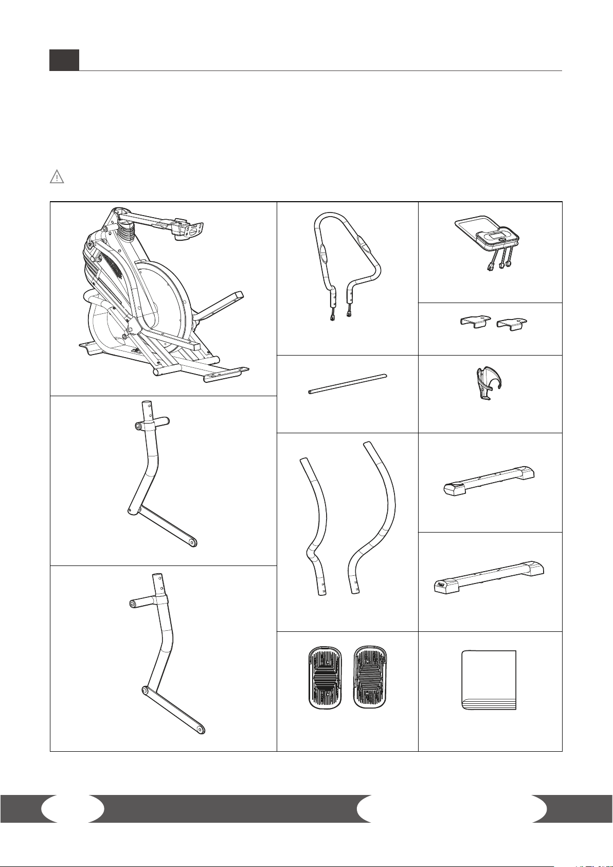
Left Swing Rod with Connect Metal ×1set
NO. 10L / 10R
Pedal (L/R) ×1set User Manual ×1pc
NO. 29R / 25
Right Swing Rod with Connect Metal ×1set
NO. 34L / 34R
L&R Handlebar ×1set
NO. 3
Rear Bottom Tube ×1pc
NO. 2
Front Bottom Tube ×1pc
NO. 49
Long Axis ×1pc
NO. 89
Bottle Holder ×1pc
NO. 86
Middle Handlebar ×1set
NO. 83
Pedal Subplate ×1set
NO. 41
Monitor × 1pc
NO. 1 / 9L / 9R / 39
Main Fame ×1set
3ASSEMBLY INSTRUCTION
3.2 Scope of Delivery
The scope of delivery consist of the following parts. At the beginning, check whether all parts
and tools belonging to the device are included in the scope of delivery and whether damage has
occurred. In the event of complaints, the contractual partner must be contacted directly.
CAUTION
If parts of the scope of delivery are missing or damaged, the assembly must not be carried out.

11
NO.4 Screw (M8×55) × 8pcs
NO.33 Screw (M8×16) × 2pcs
NO.6
Flat Washer (D8) × 8pcs
NO.5
Spring Washer (D8) × 8pcs
Step 1 Step 2
NO.11 Bolt (B8×50) × 4pcs
NO.6
Washer (D8) × 4pcs
NO.12
Nylon Nut (M8) × 4pcs
Step 3
Step 4 Step 5
NO.30 Washer (ø16×ø28) × 2pcs NO.26 Bolt (M8×ø9) × 2pcs
NO. 37 Nut (M8) × 4pcs
NO. 35 Bolt (M8×40) × 4pcs NO. 37 Nut (M8) × 4pcs
NO. 87 Screw (M8×35) × 4pcs
Wrench (S13/14/15) × 1pc Wrench × 2pcs
NO.42 Screw (M8×40) × 1pc
NO. 36 Washer (D8) × 4pcs NO. 36 Washer (D8) × 4pcs
NO.32 Spring Washer (D8) × 2pcs NO.95 Wave Washer (ø26×ø16×0.3) × 2pcs
NO.31 Washer (D8×ø28) × 2pcs
3ASSEMBLY INSTRUCTION
12 MXT40-M2 APEX TRAINER
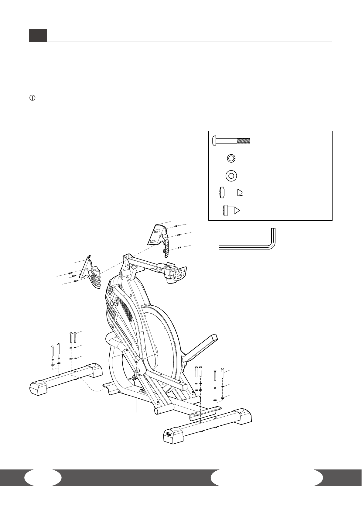
NO.4 Screw (M8×55) × 8pcs
NO.6 Flat Washer (D8) × 8pcs
NO.72 Screw (ST4.2×20) × 2pcs
NO.73 Screw (ST4.2×12) × 4pcs
NO.5 Spring Washer (D8) × 8pcs
Wrench × 1pc
4
73
70R
70L
72
73
73 72
73
5
6
4
1
3
5
6
2
3ASSEMBLY INSTRUCTION
3.3 Assembly
Before assembly, take a close look at the individual assembly steps shown and carry out the
assembly in the order given.
NOTICE
First loosely screw all parts together and check that they t properly. Tighten the screws using
the tool only when you are instructed to do so.
Step 1: Assembly of the Stabilizers and the Covers
1. Mount the front stabilizer (2) and the rear stabilizer
(3) to the main frame (1) with four screws (4), four
spring washers (5) and four washers (6) on each of the
stabilizers (2 & 3).
2. Mount the left and right decorative covers (70L & 70R)
to the main frame (1) with two screws (73) and one
screw (72) on each side.
13
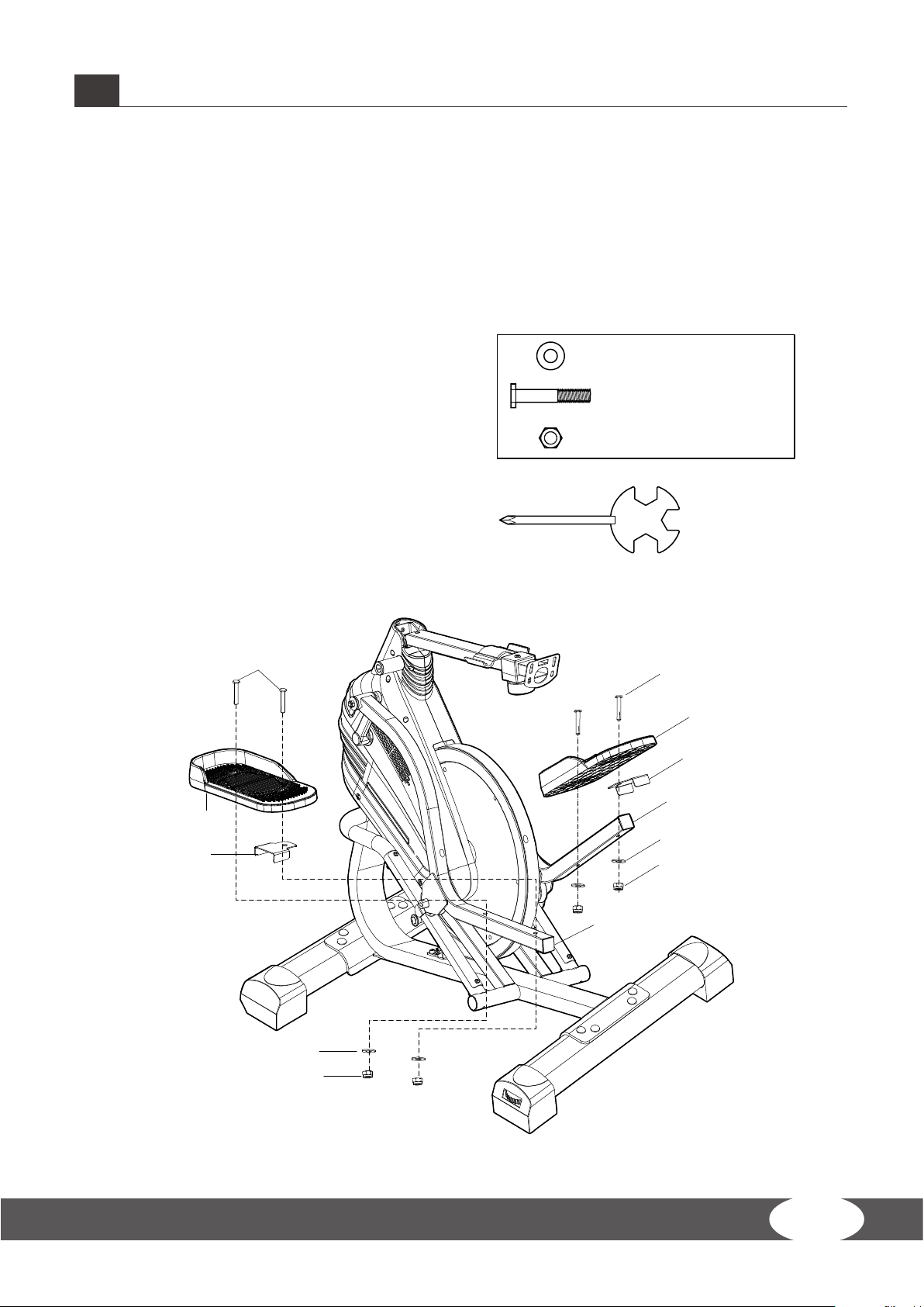
NO.11 Bolt (B8×50) × 4pcs
NO.6 Washer (D8) × 4pcs
NO.12 Nylon Nut (M8) × 4pcs
Wrench (S13/14/15) × 1pc
11
11
6
12
6
12
83
83
10R
10L
9R
9L
3ASSEMBLY INSTRUCTION
Step 2: Assembly of the Pedals
1. Place one pedal plate (83) on each of the pedal welds (9R & 9L).
2. Mount the pedals (10R & 10L) to their respective pedal weld (9R & 9L) with two screws (11), two
washers (6) and two nylon nuts (12) on each side.
14 MXT40-M2 APEX TRAINER
49
29L
26 27 25 27 1
9L 9R
29R
95
31 30
32
33
95
31
30
32
33
26
27
25
27
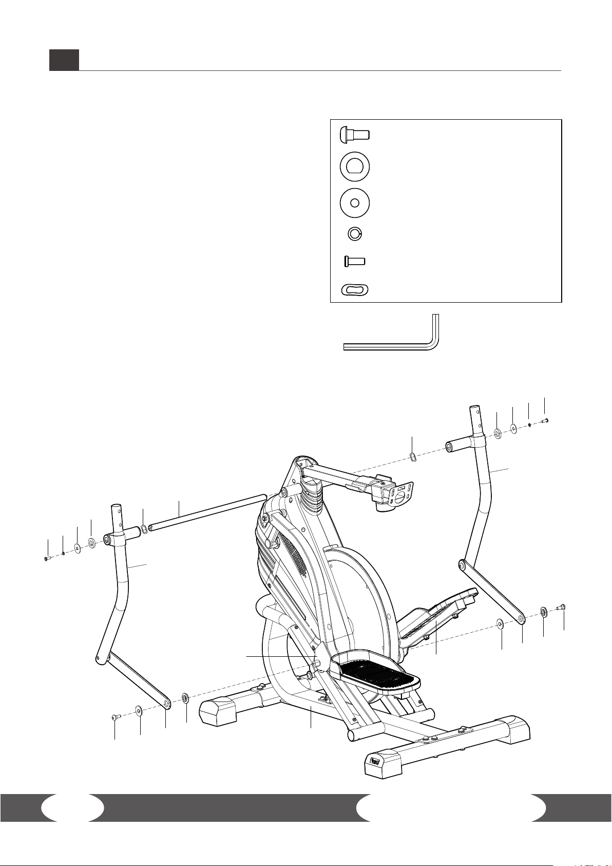
Wrench × 1pc
NO.33 Screw (M8×16) × 2pcs
NO.30 Washer (ø16×ø28) × 2pcs
NO.26 Bolt (M8×ø9) × 2pcs
NO.32 Spring Washer (D8) × 2pcs
NO.95 Wave Washer (ø26×ø16×0.3) × 2pcs
NO.31 Washer (D8×ø28) × 2pcs
3ASSEMBLY INSTRUCTION
Step 3: Assembly of the Swing Rods
1. Slide the long axis (49) through the connection at
the top centre of the main frame (1).
2. Mount the right swing rod (29R) to the right of
the long axis (49) with one screw (33), one spring
washer (32), one washer (31), one washer (30) and
one wave washer (95).
3. Mount the connect metal of the right swing rod
(25) to the right pedal weld (9R) with one screw (26)
and two washers (27).
4. Repeat the steps 2 and 3 on the left side.
15
34R
29R
29L
35
36
37
34L
1
36
37
35
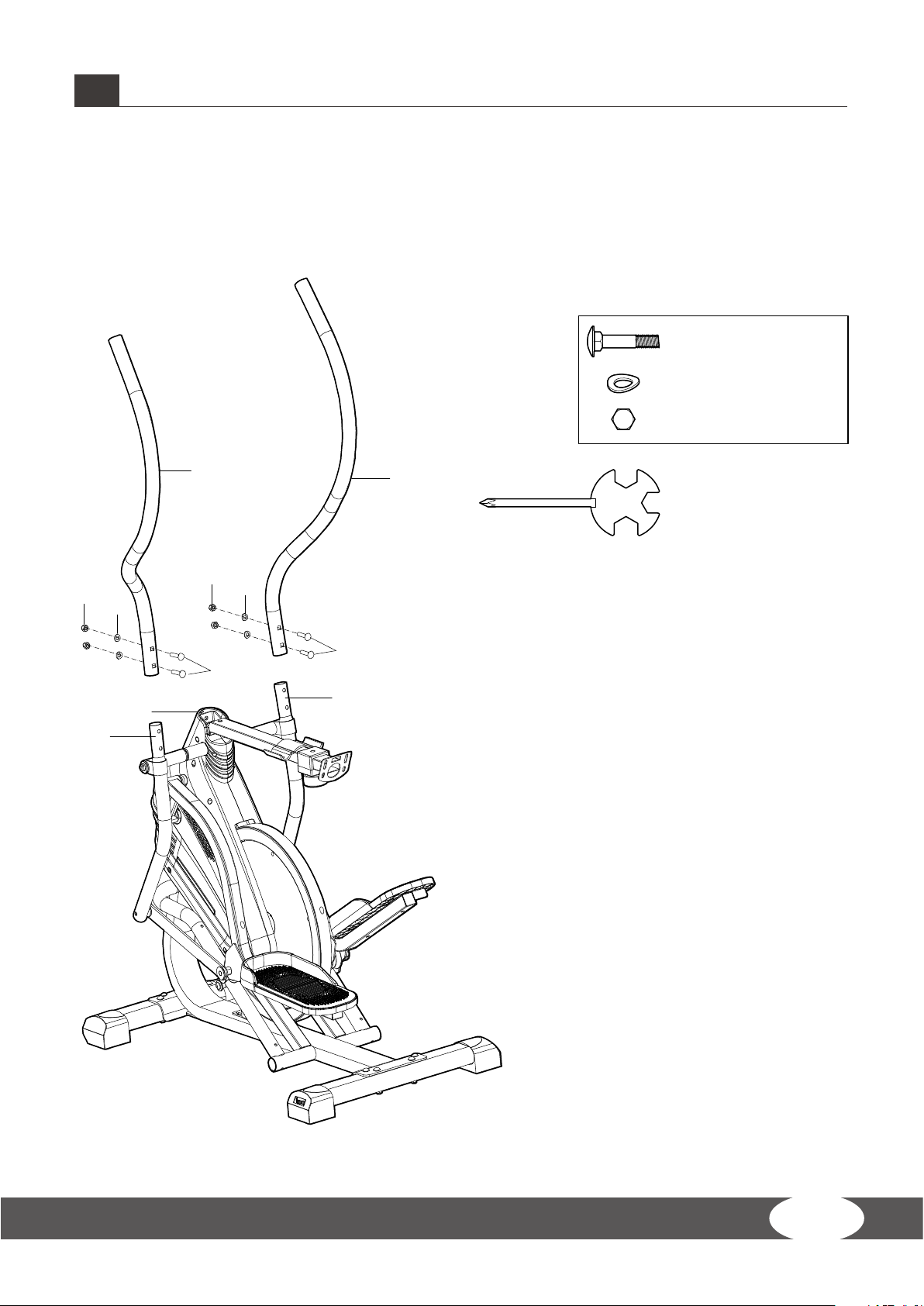
Wrench (S13/14/15) × 1pc
NO. 37 Nut (M8) × 4pcs
NO. 35 Bolt (M8×40) × 4pcs
NO. 36 Washer (D8) × 4pcs
3ASSEMBLY INSTRUCTION
Step 4: Assembly of the Handlebars
Mount the left and right handlebars (34L & 34R) to their respective swing rod (29L & 29R) with two
screws (35), two washers (36) and two nuts (37) on each side.
16 MXT40-M2 APEX TRAINER
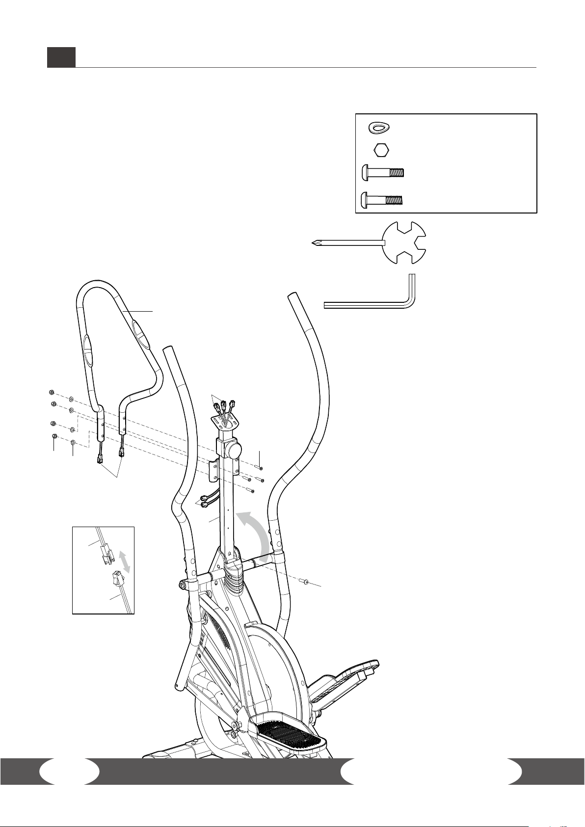
Wrench (S13/14/15) × 1pc
Wrench × 1pc
NO. 37 Nut (M8) × 4pcs
NO. 87 Screw (M8×35) × 4pcs
NO.42 Screw (M8×40) × 1pc
NO. 36 Washer (D8) × 4pcs
86
90
96
96
87
96
36
90
42
37
39
3ASSEMBLY INSTRUCTION
Step 5: Assembly of the Middle Handlebar
1. Slide the mid handlebar weld (39) into the main
frame (1).
2. Mount the mid handlebar weld (39) to the main
frame (1) with one screw (42).
3. Mount the middle handlebar (86) to the mid
handlebar weld (39) with four screws (87), four
washers (36) and four nuts (37).
4. Connect the hand pulse sensors of the middle
handlebar (90) to the lower cables of the mid
handlebar weld (96).

17
Wrench (S13/14/15) × 1pc
NO. 84 Screw (M5×10) × 2pcs
NO. 92 Screw (M5×10) × 2pcs
86
84
89
80
96
92
41
39
96
41
4141
9680
3ASSEMBLY INSTRUCTION
Step 6: Assembly of the Monitor and the Bottle Holder
1. Connect the cables of the mid handlebar weld (80
& 96) to the cables of the monitor (41).
ATTENTION
Make sure not to pinch the cables during the
following step.
2. Mount the monitor (41) to the mid handlebar
weld (39) with two screws (84).
3. Mount the bottle holder (89) to the mid handlebar weld (39) with two screws (92).
4. Now tighten all screw joints with the necessary tools.
→The assembly of the equipment is completed.
Step 7: Alignment of the Feet
If the oor is uneven, you can stabilize the equipment by turning the setting screws under the main
frame.
1. Lift the equipment on the desired side and rotate the setting screws under the main frame.
2. Rotate the screws clockwise in order to remove them and to raise the equipment.
3. Rotate the screws counterclockwise in order to lower the equipment.

18 MXT40-M2 APEX TRAINER
NOTICE
Familiarise yourself with all the functions and setting options of the device before starting
training. Have the proper use of this product explained to you by a specialist.
4.1 Console Display
Scan Displays a dierent training value every six seconds
Time Displays the remaining or elapsed training time (00:00 -99:59 min)
Speed Displays the current training speed (0 - 999.9 km/h)
Distance Displays the remaining distance or the distance traveled
Odometer Displays the total amount of distance traveled since rst use (0 - 9999 km)
Calories Displays the total amount of burned calories (0 - 9999 kcal)
Pulse Rate
Displays the current heart rate.
WARNING
Your training equipment is not a medical device. The heart rate
measurement of this equipment may be inaccurate. Various factors
can aect the accuracy of the heart rate measurement. The heart rate
measurement serves only as a training aid.
Battery AAA Battery (2x)
Operating Temperature 0 ~ 40°C (32 °F ~ 104 °F)
Storage Temperature -10 ~ 60°C
4.2 Functions Button
Functions Button
+By pressing the functions button, you can choose between functions,
such as TIME - SPEED - DIST - CALORIES(CAL) -ODO - PULSE RATE
wechseln
+In order to reset a value, press and then hold the respective button for
3 seconds
4.3 Hibernation
The console enters hibernation mode automatically if the sensor does not receive a signal.
The console will turn on again once the functions button is pressed or the sensor receives a signal.
4OPERATING INSTRUCTIONS

19
5STORAGE AND TRANSPORT
5.1 General Instructions
WARNING
+ The storage location should be chosen so that improper use by third parties or children can
be prevented.
+ If your equipment does not have transportation wheels, the equipment must be
disassembled before transportation.
ATTENTION
+ Make sure that the equipment is protected from moisture, dust and dirt in the selected
storage location. The storage location should be dry and well ventilated and have a constant
ambient temperature between 10°C and 35°C.
5.2 Folding Mechanism
ATTENTION
+ If you want to transport your equipment over particularly sensitive and soft oor coverings,
such as parquet, planks or laminate, lay out the transport route with cardboard or similar to
avoid possible oor damage.
1. Stand in front of the equipment and lift it until the weight is transferred to the transportation
wheels. After that, you easily can move the equipment to a new position. For long transport
distances the equipment should be disassembled and safely packed.
2. Select the new location by following the instructions in the section 1.3 of this manual.
20 MXT40-M2 APEX TRAINER
6TROUBLESHOOTING, CARE AND MAINTENANCE
6.1 General Instructions
WARNING
+ Do not make any improper changes to the equipment.
CAUTION
+ Damaged or worn components may aect your safety and the life of the equipment.
Therefore, immediately replace damaged or worn components. In such a case, contact the
contract partner. The equipment must not be used until it has been repaired. If necessary, use
only original spare parts.
ATTENTION
+ In addition to the instructions and recommendations for maintenance and care given here,
additional service and/or repair work may be necessary; this must only be carried out by
authorised service technicians.
6.2 Faults and Fault Diagnosis
The equipment undergoes regular quality controls during production. Nevertheless, faults or
malfunctions may occur. Frequently, individual parts are responsible for these disturbances, an
exchange is usually sucient. Please refer to the following overview for the most common errors
and how to correct them. If the equipment still does not function properly, contact your contract
partner.
Fault Cause Solution
Drive disks wobble/make
noises Drive disk loose Tighten nut (pay attention to left-
hand / right-hand thread)
Display is blank/is not working Loose cable connections Check cable connections
Equipment wobbles Equipment is not level Align the feet
Creaking noises on the
stepping area
Loose screws on stepping
area
Tighten the screws on the
stepping area
Creaking noises Screw connections
loosened or too tight Check screw connections
Squeaking noises on the guide
rails
Guide rails or rollers dirty
or guide rails dry
Clean the guide rails and then
lubricate them with a suitable
lubricant
No pulse display
+Sources of interference
in the room
+Unsuitable chest strap
+Wrong position of chest
strap
+Chest strap defective or
battery empty
+Pulse display defective
+Eliminate sources of
interference (e.g. mobile
phone, WLAN, lawn mower and
vacuum cleaner robot, etc. ...)
+Use a suitable chest strap (see
RECOMMENDED ACCESSORIES).
+Reposition chest strap and/or
moisten electrodes
+Changing batteries
+Check if pulse display by hand
pulse possible
Table of contents
Other BODYMAX Exercise Bike manuals

BODYMAX
BODYMAX FXB10 User manual

BODYMAX
BODYMAX B50 User manual

BODYMAX
BODYMAX 40 User manual

BODYMAX
BODYMAX CVEB2419 User manual

BODYMAX
BODYMAX FXB30 User manual

BODYMAX
BODYMAX B2 User manual

BODYMAX
BODYMAX B15 User manual

BODYMAX
BODYMAX 80 User manual

BODYMAX
BODYMAX RB60 User manual

BODYMAX
BODYMAX B200 User manual
Popular Exercise Bike manuals by other brands


Sunny Health & Fitness
Sunny Health & Fitness SF-B121021 user manual

Monark
Monark 827E instruction manual

Stamina
Stamina 1310 owner's manual

American Fitness
American Fitness SPR-BK1072A owner's manual
 Service manual")
Cateye
Cateye CS-1000 (CYCLO SIMULATOR) Service manual

BH FITNESS
BH FITNESS H9158H Instructions for assembly and use