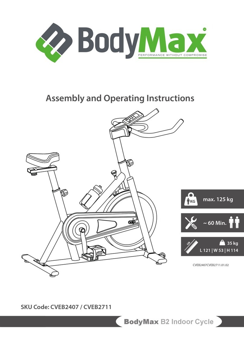
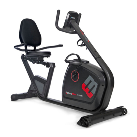
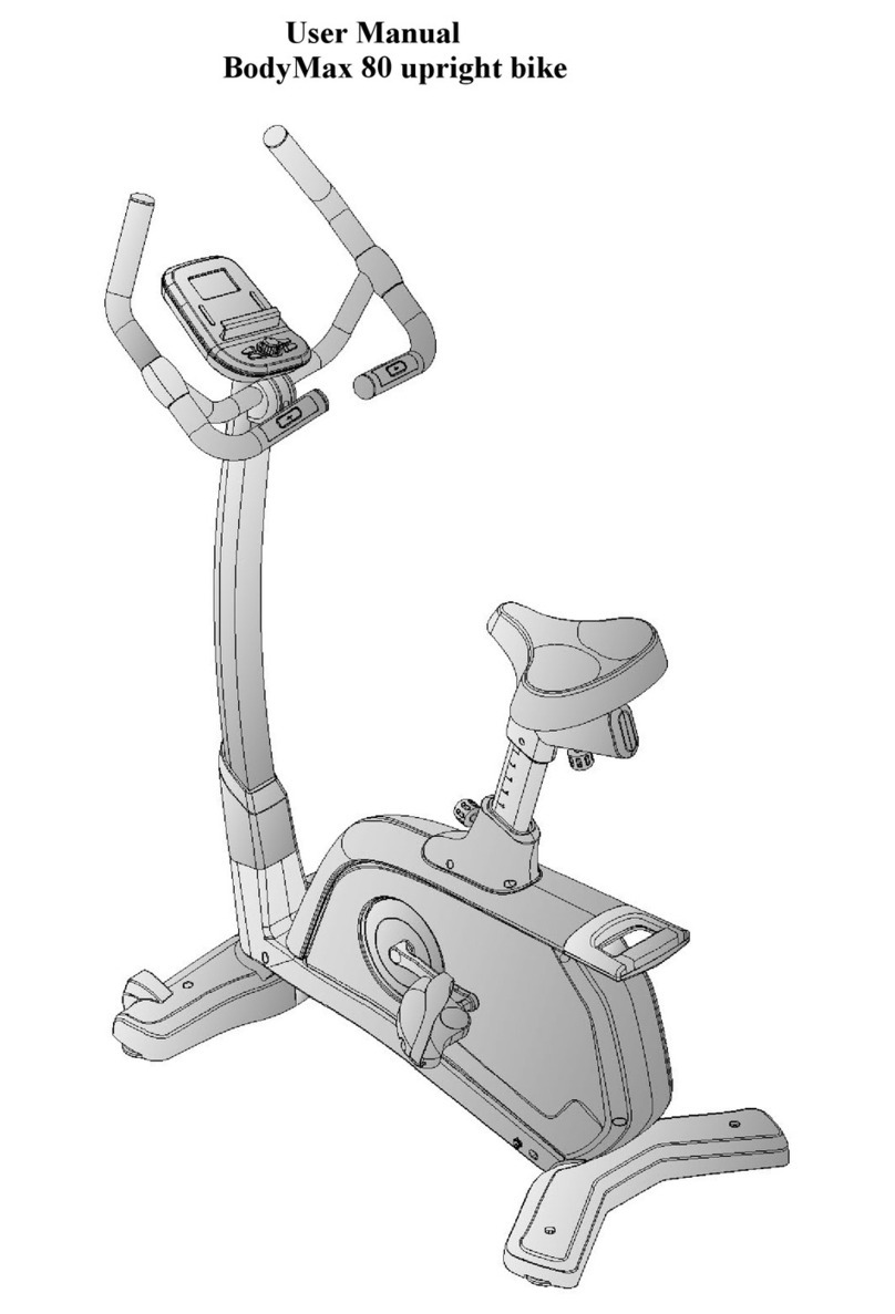
BODYMAX 40 User manual

USER’S MANUAL
BodyMax 40 upright bike
1

Safety Instructions
2

3

•
To en ure the be t afety of the exerci er, regularly
check it on damage and worn part .
• If you pa on thi exerci er to another per on or if
you allow another per on to u e it, make ure that
that per on i familiar with the content and
in truction in the e in truction .
• Only one per on hould u e the exerci er at a time.
• Before the fir t u e and regularly make ure that all
crew , bolt and other joint are properly tightened
and firmly eated.
• Before you tart your work-out, remove all harp-
edged object around the exerci er.
• Only u e the exerci e for your work-out if it work
flawle ly.
• Any broken, worn or defective part mu t
immediately be replaced and/or the exerci er mu t
no longer be u ed until it ha been properly
maintained and repaired.
• Parent and other upervi ory per on hould be
aware of their re pon ibility, due to ituation which
may ari e for which the exerci er ha not been
de igned and which may occur due to children’
natural play in tinct and intere t in experimenting.
• If you do allow children to u e thi exerci er, be
ure to take into con ideration and a e their
mental and phy ical condition and development,
and above all their temperament. Children hould
u e the exerci er only under adult upervi ion and
be in tructed on the correct and proper u e of the
exerci er. The exerci er i not a toy.
• Make ure there i ufficient free pace around the
exerci er when you et it up.
• To avoid po ible accident , do not allow children to
approach the exerci er without upervi ion, ince
they may u e it in a way for which it i not intended
due to their natural play in tinct and intere t in
experimenting.
• Plea e note that an improper and exce ive work-
out may be harmful to your health.
• Plea e note that lever amd other adju tment
mechani m are not projecting into the area of
movement during the work-out.
• When etting up the exerci er, plea e make ure
that the exerci er i tanding in a table way and
that any po ible unevenne of the floor i
evened out.
• Alway wear appropriate clothing and hoe
which are uitable for your work-out on the
exerci er. The clothe mu t be de igned in a way
o that they will not get caught in any part of the
exerci er during the work-out due to their form (for
example, length). Be ure to wear appropriate
hoe which are uitable for the work-out, firmly
upport the feet and which are provided with a
non- lip ole.
• Be ure to con ult a phy ician before you tart
any exerci e program. He may give you proper
hint and advice with re pect to the individual
inten ity of tre for you a well a to your work-
out and en ible eating habit .
4

• A emble the exerci er a per a embly in truction
and be ure to only u e the trucutral part
provided with the exerci er and de igned for it.
Prior to the a embly, make ure the content of
the delivery i complete by referring to the part li t
of the a embly and operating in truction .
• Be ure to et up the exerci er in a dry and even place and
alway protect it from humidity. If you wi h to protect the place
particularly again t pre ure point , contamination, etc.,
it i recommended to put a uitable, non- lip mat under the exerci e
• The general rule i that exerci er and training device are no
toy . Therefore, they mu t only be u ed by properly informed
or in tructed per on .
•Stop your work-out immediately in ca e of dizzine ,
nau ea, che t pain or any other phy ical ymptom . In
ca e of doubt, con ult your phy ician immediately.
•Children, di abled and hadicapped per on hould
u e the exerci e only under upervi ion and in
pre ence of another per on who may give upport
and u eful in truction .
•Be ure that your body part and tho e of other
per on are never clo e to any moving part of the
exerci er during it u e.
•When adju ting the adju table part , make ure they
are adju ted properly and note the marked, maximum
adju ting po ition, for example of the addle upport,
re pectively.
•Do not work out immediately after meal !
5

Exploded drawing
6

Part List
Part no. Description Drawing no. Material Specification Q'ty
1Main frame 800A1-3-1000-B0 1
2Rear tabilizer 16100-6-2101-B1 Q195 D60x1.5Tx480L 1
3Adju table cap 55450-5-0060-B1 PP5070 D60xD75x50L 2
4Front tabilizer 19000-6-2101-B5 Q195 D60x500Lx1.5T 1
5round foot cap 55443-1-0060-B3 PVC D60xD67x43 2
6Domed nut M8x1.25x15L 55208-6-2015-FA 35# M8x1.25x15L 4
7Allen bolt M8*1.25*80L 50308-5-0080-F3 35# M8*1.25*80L 4
8Oval cap 55328-3-2550-B1 PP 25*50*28L 2
9Seat po t 195S0-3-2200-B3 1
10 Seat DD3532 58001-6-1019-B0 PVC DD-3532 1
11 Seat adju tment tube et 70104-3-4000-B0 1
12
Spring wa her D15.4
XD8.2x2T 55108-2-1520-FA 70# D15.4xD8.2x2T 4
13
Curved wa her
D22*D8.5*1.5T 55108-3-2215-FA Q235A D22*D8.5*1.5T 10
14 emi-round moving foot cap 55454-K-0060-B1 PP5070 D60x54.5L 2
15 cro crew ST4x1.41x12L 52804-2-0012-D0 Q235A ST4*1.41*12L 4
16 Foam D20*7T*530L 58015-6-1113-B0 NBR D20*7T*530L 2
17 Flat wa her D25xD8.5x3T 55108-1-2830-NA Q235A D28*D8.5*3T 1
18 Club knob D60x32L(M8x1.25) 52008-2-0022-B0 PP+CU D60x32L(M8x1.25) 1
19 Round cap D7/8"x17L 553D7-1-0017-B1 PP D7/8"x17L 2
20 Allen bolt M8*1.25*15L 50308-5-0015-F0 35# M8*1.25*15L 6
21 Belt 58004-6-1038-00 1092L PJ5 1
22
Waved wa her D22*D17*0.3T 55117-5-2203-DA
65Mn D22*D17*0.3T 2
23 Flat wa her D23*D17.2*1.5T 55117-1-2315-NA Q235A D23*D17.2*1.5T 1
24 Flywheel et 800A1-2-3100-00 1
25 Left chain cover 800A1-6-4501-B0 PS 901.8*79.5*558.3 1
26 Right chain cover 80002-6-4502-B0 PS 901.8*75*558.3 1
27 Belt wheel 58008-6-1012-05 NL+fibre D240x21 1
28 Oval manhead 19500-6-4578-B0 ABS 1
29 Handlebar po t et 800A1-3-2000-B0 1
30 Hand pul e 16800-6-2478-00 PE18 2
handpul e cable 695M0-6-2479-00 500L 2
31 Knob 52716-2-0024-B1
Q235A+ABS71
7 D56xM16x24xD8 1
7

32 bu hing 58002-6-1067-01 F101J D20*D14*11.5 1
33 Screw cover 81502-6-2779-B0 PE D26*11L 2
34 hex Bolt M8x1.25x25 50108-2-0025-U0 35# M8x1.25x25 2
35L Left crank 58007-6-1045-02 1015A 6 1/2"x9/16"-20UNF 1
35R Right crank 58007-6-1046-02 1015A 6 1/2"x9/16"-20UNF 1
36 Handlebar 67900-6-2401-C0 Q195
D22.2x470x350x1.5
T 1
37 T Knob 51908-2-0055-B1 ABS+Q235A M8x1.25x55 1
38 Computer ST-6577-71 800C1-6-2501-B0 ST-6577-71 1
39 Allen bolt M10*35L 50310-5-0035-C3 35# M10*35L 1
40 buffer pad 800B1-6-1081-B0 NBR 23*76*1.7T 4
41 cro crew ST4*20 50904-2-0020-D0 10# ST4*20 2
42 Protective cover 69100-6-2481-B0 ABS 80.6*56*52.5 1
43 Flat wa her D16xD8.5x1.2T 55108-1-1612-FA Q235A D16xD8.5x1.2T 1
45 bu hing D8xD12.7x23 58002-6-1033-F2 Q195 D8xD12.7x23 1
46L/
46R Pedal et 58029-6-1026-B0 JD-16A 1
47 C-clip S-17(1T) 55517-1-0010-00 65Mn S-17(1T) 1
48 Nylon nut M6x1.0x6T 55206-1-2006-CA Q235A M6x1.0x6T 4
49 hex Bolt M6x1.0x15L 50106-5-0015-C0 35# M6x1.0x15L 4
50 Idle wheel 745S0-6-1671-00 NL+15% Fibre D42*D38*24 1
51 Nylon nut M10x1.5x10T 55210-1-2010-NA Q235A M10x1.5x10T 1
52 Crank axle et 19802-3-2903-01 1
53
Anti-loo en nut 3/8"-
26UNF*6.5T 18600-6-3175-N1 Q23A 3/8"-26UNFx6.5T 2
55 Bearing #6003ZZ 58006-6-1018-00 GCr15 #6003ZZ 2
56 Pin 71600-6-4586-60 ABS D6*26.5*7.7 2
57 Nylon nut M8*1.25*8T 55208-1-2008-NA Q235A M8*1.25*8T 2
58 Fixing plate for idle wheel 195S0-3-1600-N2 1
59 cro Screw M5x0.8x10L M5*10L 4
60 hex Nut M8*1.25*6T 55208-2-2006-NA Q235A M8*1.25*6T 1
61 Round magnet 174R4-6-2574-00 M02 1
62 cro Screw ST4.2x1.4x20L 53342-2-0020-N0 10# ST4.2x1.4x20L 10
63 Bu hing D22.5*D17.2*6.4T 80700-6-2781-00 Fe D22.5*D17.2*6.4T 1
64
Upper computer cable 1000L 707A1-6-2572-00
1000L 1
65 Lower computer cable 900L 12601-6-2573-00 900L 1
66 Spring D16xD8.5x1.2T Q235A D16xD8.5x1.2T 3
8

67 nylon nut Q235A M8*8T 3
68
pring 58003-6-1024-N0
72A D2.2*D14*65L 1
69 Cro bolt M5x0.8x12L 52605-2-0012-N0 Q235A M5x0.8x12L 1
70 Hollow end cap 40x80x129 55302-6-4080-B2 PE 40x80x129 1
71 Bolt cover 19100-6-3172-B0 PVC D35*8 2
72 Flat wa her D16*D8.5*1.2T 55108-1-1612-FA Q235A D16*D8.5*1.2T 4
73 Upper Ten ion cable 1130L 71700-6-2602-02 1130L 1
74 Lower Ten ion cable 640L 801A0-6-2601-B1 640L 1
78
Pla tic wa her
D50*D10*1.0T 55110-1-5010-BF NL66 D50*D10*1.0T 1
79 Flat wa her D30*D8.5*2.0T 55108-1-3020-NA Q235A D30*D8.5*2.0T 1
80 hex Bolt M8*25 50108-5-0025-N3 35# M8*25 1
81 Pla tic cover 803K0-6-1082-00 PVC D3*30L 2
82 hex Bolt M8*52L 50108-5-0052-N3 35# M8*52L 1
83 hex Bolt M6*65L 50106-5-0065-N0 35# M6*65L 1
84 Spring D1.0*55L 58003-6-1054-N0 72A D1.0*55L 1
85 hex Nut M6*1*6T 55206-2-2006-NA Q235A M6*1*6T 1
86 Fixing bracket for magnet 706E2-3-3200-N0 1
87 Nylon nut M6*1*6T 55206-1-2006-NA Q235A M6*1*6T 1
88 Nylon wa her D6*D19*1.5T 55106-1-1915-B1 NL66 D6*D19*1.5T 1
89 Flat wa her D13*D6.5*1.0T 55106-1-1310-NA Q235A D13*D6.5*1.0T 1
90 Magnet ca e 58020-6-1003-M0 PE 40*3*3 6
91 Magnet 58009-6-1007-01 NDFEB 39.5*10*25 7
\ Inner Allen panner 58030-6-1031-D1 35# M6 1
\ panner 58030-6-1005-N2 Q235A 121*D6 1
9

CHECK LIST (CONTENTS OF PACKAGE)
10

STEP 1
1) A emble the front tabilizer (4) and rear tabilizer (2) onto the main frame (1) by
u ing the domed nut (6), the Allen bolt (7) , the pring wa her (12) and the
Curved wa her (13).
2) Adju t the proper height by turning the wheel of rear foot cap.
11

STEP 2
1) A emble the eat (10) to eat po t (9) by u ing the flat wa her (17) and Club
knob (18) .
2) Fix the eat po t (9) to the main frame (1) by u ing the knob (31)
12

3) You can adju t the addle UP/DOWN or FRONTWARD/BACKWARD.
STEP 3
1) Sugge t a embling thi tep by two per on .
2) Fir t, lift up the upper protective cover (28) like fig. (a), then connect the computer
cable (64 & 65) and ten ion control cable (73 & 74) like fig.(b & A)
3) In ert the handlebar po t (29) on the main frame and tighten it by u ing the
curved wa her (13), the Allen bolt (20) and the flat wa her (72). Place down the
upper protective cover and make it tight on the main frame.
4) A emble the handlebar (36) to the handlebar po t (29) by u ing the protective
13

cover (42), the flat wa her (43), the pring wa her (12), the bu hing (45) and the
ball haped knob (37).
STEP 4
1) Connect the upper computer cable (64) and the handle pul e cable (30) with
computer (38) and then fixing the computer (38) on the handlebar po t (29) by
u ing the bolt (59) .
2) Fixing the pedal (46L & 46R) to the crank (35L & 35R).
14

Instruction Manual of ST6577-71
BUTTONS:
MODE To confirm all settings
Joggle wheel - UP To select training mode and adjust function value up
Joggle wheel - DOWN To select training mode and adjust function value down
RESET To clear the set-up value Press RESET key and hold for 2 seconds to reset all function figures
TOTAL RESET To power on the console again
RECOVERY To test heart rate recovery status
BODY FAT : To start or stop body fat testing
FUNCTIONS:
SCAN: Displays all function TIME→DISTANCE→CALORIES→PULSE→ RPM/SPEED in sequence
RPM: Displays the pedaling Rotation Per Minute The RPM and SPEED will switch to another display in every 6
seconds after exercise starts
SPEED: Displays the user’s exercise speed
TIME: 1 You can use joggle wheel to set target time between 0:00 to 99:00 for count down function
2 It can be set up by the user or accumulated automatically for count up function
DISTANCE: 1 Your can use joggle wheel to set target distance between 0 00 to 99 50 for count down function
2 It can be set up by the user or accumulated automatically for count up function
CALORIES: 1 You can use joggle wheel to set target calories between 0 to 9990 for count down function
2 It can be set up by the user or accumulated automatically for count up function
BODY FAT In STOP mode, pre the BODY FAT button to tart body fat mea urement.
During mea uring, u er ha to hold both hand on the handgrip. And the LCD will di play “-” “--““---” “----“
for 8 econd until computer fini h mea uring.
LCD will di play BMI, FAT% by turn every 3 econd .
OPER TION PROCEDURE:
1 Installs 2 pieces of 1 5V #3 batteries, then the screen will display as following “Drawing A” and have “Bi” sound at the
same time, then enter to the personal data setting and press “MODE” button for confirmation After that, it goes to the next
step to the main menu as “Drawing B”
15

Drawing A Drawing B
2 Get access to the set-up mode of TIME/DISTANCE/CALORIES/PULSE When you are in each set- up mode, for
example in the time set-up mode, time value is blinking, you can use joggle wheel to adjust the value and press
“MODE” for confirmation The set-up of DISTANCE, CALORIES & PULSE is the same as TIME
3 With any signal been transmitted into the monitor, the value of TIME, DISTANCE, CALORIES start to count up as
Drawing C When there is any function has been preset the target (TIME or DISTANCE or CALORIES), the function
will be counting down from the preset to zero while the training starts Once the target is achieved to zero, the monitor
start to beep for 8 seconds, and the function will be counting up from zero directly if the training is going Press
“MODE” button for confirmation and skip to next set-up
4 In SCAN mode shown as “Drawing C” RPM/SPEED/TM/DIST/CAL/PULSE will skip to display in every 6 seconds
The order is as follows
Drawing C
5 You can also press “MODE” button to select single function display except RPM & SPEED function The RPM &
SPEED function will switch display
6 RECOVERY:
(1)When the user presses “RECOVERY” button, the RECOVERY function is active At this time only
PULSE and TIME is working, other functions will not be displayed, and the Sensor Input is not
available TIME starts to count down from ”0:60”, Pulse signal will be blinking according user’s
heart rate BPM When Time counts down to “0”, it will show F1~F6
(F1 is the best, F6 is the worst)
(2)LCD display as follows: (RECOVERY start condition & end condition)。
(3)If the count down action to 0:00 is not completed and there is no pulse signal, the count down action has to be done
and shown F6
16

(4)If you press the RECOVERY button prior to count down to 0:00, it will be end and return to the main menu
Note:
1 Stop training for 4 minutes, the main screen will be off
You may press any button to have the computer restart working, the original value will retain
(If re-install batteries, the original value will remove )
2 If the computer displays abnormally, please re-install batteries and try again
3 Battery Spec: 1 5V UM-3 or AA (2PCS)
17
Table of contents
Other BODYMAX Exercise Bike manuals

BODYMAX
BODYMAX B15 User manual

BODYMAX
BODYMAX FXB30 User manual

BODYMAX
BODYMAX 80 User manual

BODYMAX
BODYMAX B200 User manual

BODYMAX
BODYMAX RB60 User manual

BODYMAX
BODYMAX CVET2706 User manual

BODYMAX
BODYMAX B2 User manual

BODYMAX
BODYMAX CVEB2419 User manual

BODYMAX
BODYMAX B50 User manual

BODYMAX
BODYMAX FXB10 User manual