BODYMAX 80 User manual
User Manual
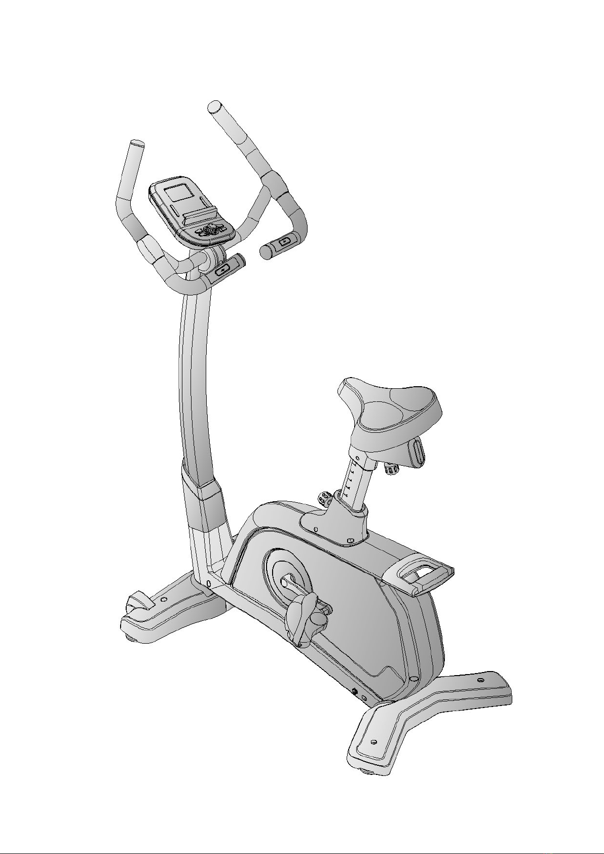
BodyMax 80 upright bike

Safety Instructions


• To ensure the best safety of the exerciser, regularly check it
for damage and worn parts.
• If you pass on this exerciser to another person or if you allow
another person to use it, make sure that that person is familiar
with the content and instructions in these instructions.
• Only one person should use the exerciser at a time.
• Before the first use and regularly make sure that all screws,
bolts and other joints are properly tightened and firmly seated.
• Before you start your work out, remove all sharp edged objects
around the exerciser.
• Only use the exercise for your work out if it works flawlessly.
• Any broken, worn or defective part must immediately be
replaced and/or the exerciser must no longer be used until it
has been properly maintained and repaired.
• Parents and other supervisory persons should be aware of their
responsibility, due to situations which may arise for which the
exerciser has not been designed and which may occur due to
children’s natural play instinct and interest in experimenting.
• If you do allow children to use this exerciser, be sure to take into
consideration and assess their mental and physical condition
and development, and above all their temperament. Children
should use the exerciser only under adult supervision and be
instructed on the correct and proper use of the exerciser. The
exerciser is not a toy.
• Make sure there is sufficient free space around the exerciser
when you set it up.
• To avoid possible accidents, do not allow children to approach
the exerciser without supervision, since they may use it in a way
for which it is not intended due to their natural play instinct and
interest in experimenting may place them at risk .
• Please note that an improper and excessive work out may be
harmful to your health.
• Please note that levers and other adjustment mechanisms are
not projecting into the area of movement during the work out.
•When setting up the exerciser, please make sure that the
exerciser is standing in a stable way and that any possible
unevenness of the floor is evened out.
•Always wear appropriate clothing and shoes which are
suitable for your work out on the exerciser. The clothes must
be designed in a way so that they will not get caught in any
part of the exerciser during the work out (for example,
length). Be sure to wear appropriate shoes which are suitable
for the work out, firmly support the feet and which are
provided with a non slip sole.
•Be sure to consult a physician or exercise professional before
you start any exercise program. He may give you proper hints
and advice with respect to the individual intensity of stress for
your work out and sensible eating habits.
• Be sure to set up the exerciser in a dry and even place and
always protect it from humidity. If you wish to protect the floor
particularly against pressure points, contamination, etc. it is
recommended to put a suitable, non slip mat under the
exercise
• The general rule is that exercisers and training devices are
not toys. Therefore, they must only be used by properly
informed or instructed persons
•Stop your work out immediately in case of dizziness, nausea,
chest pain or any other physical symptoms. If in any doubt,
consult your physician immediately.
•Children, disabled and handicapped persons should use the
exercise only under supervision and in presence of another
person who may give support and useful instructions.
•Be sure that your body parts and those of other persons are
never close to any moving parts of the exerciser during its use
•When adjusting the adjustable parts, make sure they are
adjusted properly and note the marked, maximum adjusting
position, for example of the saddle support, and seat height
post .
•Do not work out immediately after meals!

Exploded drawing:
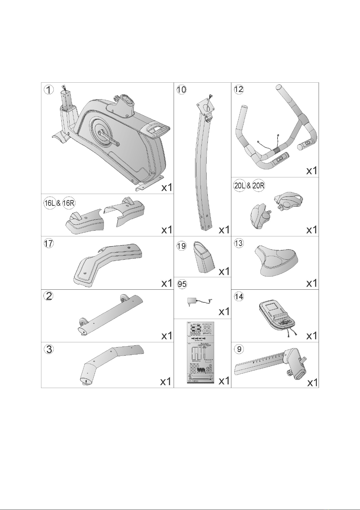
Checking list:

Part list:
Part no. Description Drawing no. Material Specification Q' ty
1 Main frame 746A2 3 1000 J0 1
2 Front stabilizer 746S1 3 2100 J0 1
3 Rear stabilizer 746S1 3 2112 J0 1
4 Bolt 50308 5 0050 F3 35# M8x1.25x50L 4
5 Spring washer 55108 2 1520 FA 70# D15.4xD8.2x2T 9
6 Flat washer 55108 1 2520 FA Q235A D25xD8.5x2T 2
7 Flat washer 55108 1 1812 FA Q235A D18xD8.5x1.2T 9
8 Bolt 50308 5 0020 F0 35# M8x1.25x20L 6
9 Seat post tube 745S0 3 2200 J1 1
10 Handlebar post tube 746A2 3 2000 J0 1
11 Seat adjustable tube 745S0 3 4000 J3 1
12 Handlebar welding set 737L6 3 2400 J3 1
13 Seat 58001 6 1336 BB0 PVC DD 3618 1
14 Computer 746B2 6 2501 B0 SM 1730 31 1
15 Bolt 52605 5 0010 F0 10# M5*0.8*10L 4
16L Front stabilizer cover(left) 833S0 6 2186 B0 HIPS88 266.1*160.7*72.9 1
16R Front stabilizer cover(right) 833S0 6 2187 B0 HIPS88 262.6*160.7*72.9 1
17 Rear stabilizer cover 833S0 6 2188 B0 HIPS88 530.6*225*64.3 1
18 Pull knob(two) 737L6 6 2284 B0 Q235A+ABS D50*M16*1.5*22 1
19 upper cover 709S0 6 4580 B0 HIPS88 1
20L/20R pedal set 58029 6 1032 B0 PP+Q235A JD 22A 9/16"tooth 1
21 Middle empty plug 55302 6 4080 B2 PE 40x80x129 1
22 Inner tube 78000 6 1071 B1 PE 61*55*114.5 1
23 Pull knob 746S1 6 1072 B0 Q235A+ABS D50*M16*1.5*27L 1
24L Left crank 58007 6 1088 D0 1015A+ABS 170Lx9/16" 20BC 1
24R Right crank 58007 6 1089 D0 1015A+ABS 170Lx9/16" 20BC 1
25 Bearing 58006 6 1018 00 NTN #6003ZZ 2
26 Crank welding set 745S0 3 2903 01 1
27 belt 58004 6 1030 01 1118 PJ5 1
28 Belt wheel 58008 6 1017 03 ZL102 D260*19 1

29 Bolt 50206 5 0015 C0 35# M6x1.0x15L 4
30 Anti loose nut 55206 1 2006 CA Q235A M6x1.0x6T 4
31 Inner tube 745S0 6 1071 B0 PE 40*80*39L 2
32L Seat cover(left) 746S0 6 2282 B0 ABS 262.5*31.8 1
32R Seat cover(right) 746S0 6 2283 B0 ABS 262.5*24.8 1
33 Screw 50805 2 0012 D0 Q235A M5*0.8*12L 3
34 Spacer ring 80700 6 2781 00 Fe D22.5*D17.2*6.4T 1
35 Waved washer 55117 5 2203 DA 65Mn D22xD17x0.3T 1
36 Flat washer 55117 1 2315 NA Q235A D23*D17.2*1.5T 1
37 C ring 55517 1 0010 00 65Mn S 17(1T) 1
38 Bolt 54408 6 0025 U0 35# M8*1.0*25,10.9 2
39 Screw cover 81502 6 2779 B0 PE D26*11L 2
45L Left chain cover 746G0 6 4501 B0 HIPS88 901*85*578 1
45R Right chain cover 746G0 6 4502 B0 HIPS88 901*81.5*578 1
46 Rear cover(upper) 833G0 6 4538 B0 HIPS88 135*156*29.5 1
47 Rear cover(lower) 833G0 6 4539 B0 HIPS88 135*156*16 1
48 Screw 53342 2 0020 N0 10# ST4.2x1.4x20L 8
49 Pin 71600 6 4586 60 ABS D6*26.5*7.7 5
50 Buffer 55306 4 0013 B9 SBR D9*D5.8*13 2
51 Screw 50904 2 0015 N0 10# ST4*1.41*15L 2
52 Screw 50904 2 0025 N0 10# ST4*25L 2
53 Fixing plate for idle wheel 24500 6 2674 N1 Q235A 156*62.2*5T 1
54 Bolt 50310 5 0035 C3 35# M10*35L 1
55 Spacer bushing 58002 6 1081 01 D13.5*D10*9 1
56 Idle wheel 745S0 6 1671 00 D42*D38*24 1
57 Anti loose nut 55210 1 2010 CA Q235A M10x1.5x10T 1
58 Bolt 50108 5 0025 N3 35# M8*25 1
59 Plastic flat washer 55110 1 2404 BF NL66 D10*D24*0.4T 2
60 Flat washer 55108 1 3020 NA Q235A D30*D8.5*2.0T 1
61 Nut 55208 2 2006 NA Q235A M8*1.25*6T 1
62 Anti loose nut 55208 1 2008 NA Q235A M8*1.25*8T 2
63 Spring 58003 6 1024 N0 72A D2.2*D14*65L 1
64 plastic sleeve 803K0 6 1082 00 PVC D3*30L 2
65 Foam 58015 6 1350 B2 NBR D30*3T*290L,no hole 2
66 Foam 58015 6 1351 B2 NBR D30*3T*265L,with hole 2
67 Mushroom cap 553K0 1 0029 B3 PVC D1 1/4"*29L 4
68 Cover for handlebar(left) 737L6 6 4529 B0 PS D32*70 2

69 Cover for handlebar(right) 737L6 6 4530 B0 PS D32*70 2
70 Handle pulse 737L6 6 2478 00 100.3*29.5*0.4T 4
71
Handle pulse fixed
base(upper) 737L6 6 2491 B0 ABS 40*15.2 2
72
Handle pulse fixed
base(lower) 737L6 6 2492 B0 ABS 40*15.2 2
73 Handle pulse cable 81800 6 2479 00 700L 2
74 Screw 50904 2 0015 F0 10# ST4x1.41x15L 4
75 Protective cover 80502 6 2481 B0 ABS717 80.6*56*52.5 1
76 T knob 51908 2 0065 B1 Q235A+PP M8x1.25x65 1
77 Bushing 58002 6 1026 F0 Q195 D8.2xD12.7x33 1
78 Line plug 55312 1 0015 BA PVC D4*D12*13 2
80 Round wheel 84302 6 2175 00 PVC+PP D70.5*23 2
81 Spacer bushing 58002 6 1099 00 D22.2*D8.2*7T 4
82 Bolt 50308 5 0040 F3 Q235A M8*1.25*40L 2
83 Anti loose nut 55208 1 2008 FA Q235A M8*1.25*8T 2
84 Adjustable round wheel 709S0 6 2174 B0 Q235A+ABS D59*M10*40L 4
85 Screw 52842 2 0015 F0 10# ST4.2*15L 1
86 Buffer 55304 4 2508 B9 SBR D25*D4.5*8T 1
87 Bolt 52605 5 0015 F0 10# M5*0.8*15L 5
88 Tension cable 84002 6 2601 00 D1.5*300L, 1
89 upper computer cable 73002 6 2572 00 1000L 1
90 lower computer cable 73002 6 2573 01 400L 1
91
round magnet 174R4 6 2574 00 M02 1
92 sensor cable 84002 6 2576 00 250L 1
94 Power cord 195E5 6 2596 00 620L 1
95
Adaptor 804C2 6 2584 01 output:9V,500MA 1
96 Motor 73002 6 2571 00 1
97 Screw 53342 2 0015 N0 10# ST4.2x1.4x15L 4
100 Flywheel set 746A2 2 3100 00 1
101 Flywheel axle 71600 6 3171 06 45# D10x120L(3/8" 26UNF) 1
102 C ring 55510 1 0010 00 65Mn S 10(1T) 1
103 Fixed ring 71600 6 3178 B0 SBR D13*D10*1.9T 1
104 Nut 55295 2 3005 NA Q235A D9.5x5T(3/8" 26UNFx5T) 2
105 Anti slip nut 18600 6 3175 N1 Q235A 3/8" 26UNFx6.5T 2
106 Magnet fixed welding set 70702 3 3200 N1 1
107 Bolt 50108 5 0052 N3 35# M8*52L 1
108 Bolt 50106 5 0060 N0 35# M6*60L 1
109 Spring 58003 6 1054 N0 72A D1.0*55L 1
110 Nut 55206 2 2006 NA Q235A M6*1*6T 1
111 Nylon washer 55106 1 1915 B1 NL66 D6*D19*1.5T 1
112 Flat washer 55106 1 1310 NA Q235A D13*D6.5*1.0T 1
113 Anti loose nut 55206 1 2006 NA Q235A M6*1*6T 1
/ Inner hexagon cross wrench 58030 6 1031 N1 35# M6 1
/ Open spanner 58030 6 1049 C0 150*6T 1
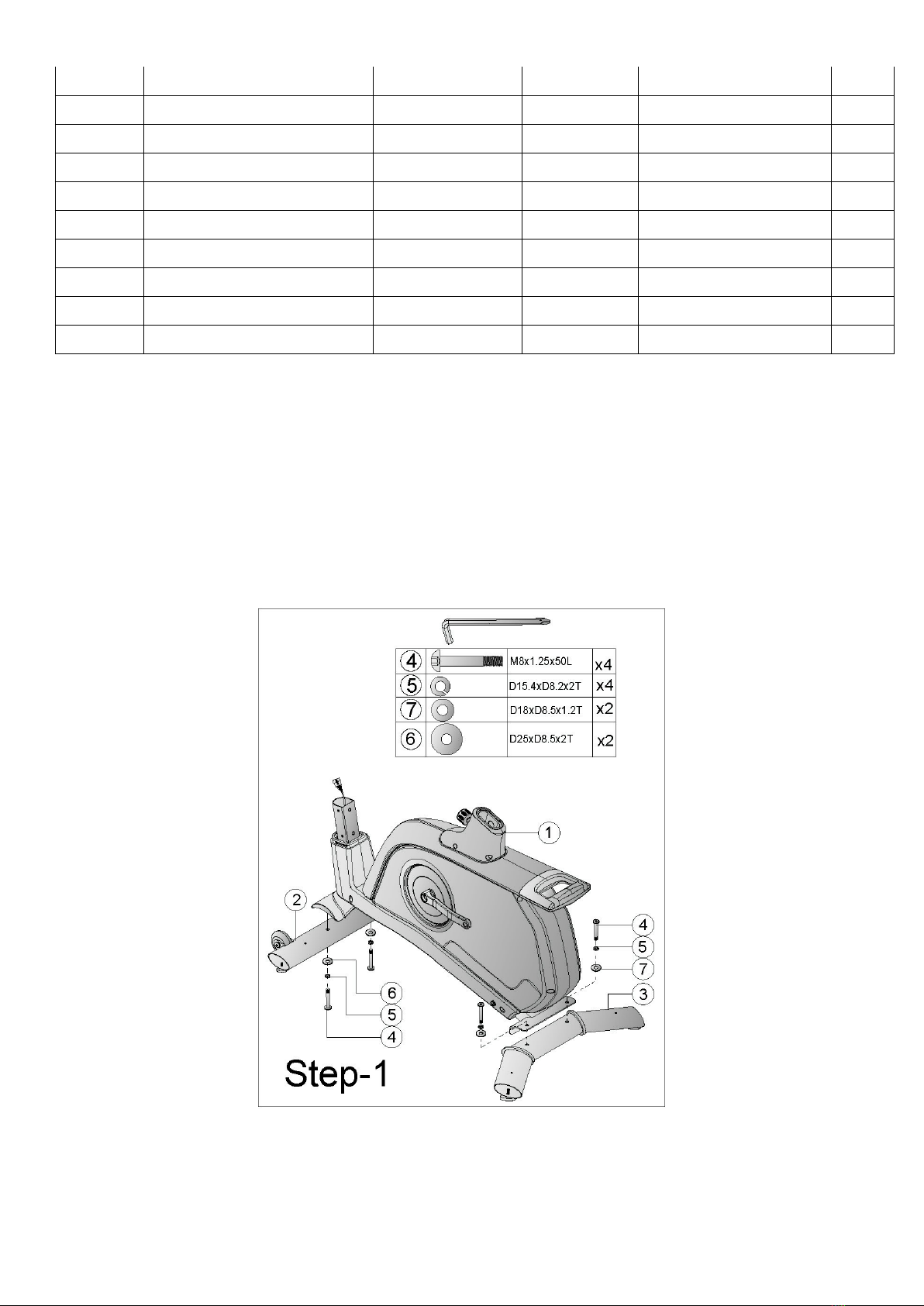
Assembly drawing:
Step 1
1) Assemble the front stabilizer (2) and the rear stabilizer (3) to the main frame (1) by Allen
bolt (4), pring washer (5) , Flat washer (6) and Flat washer (7).
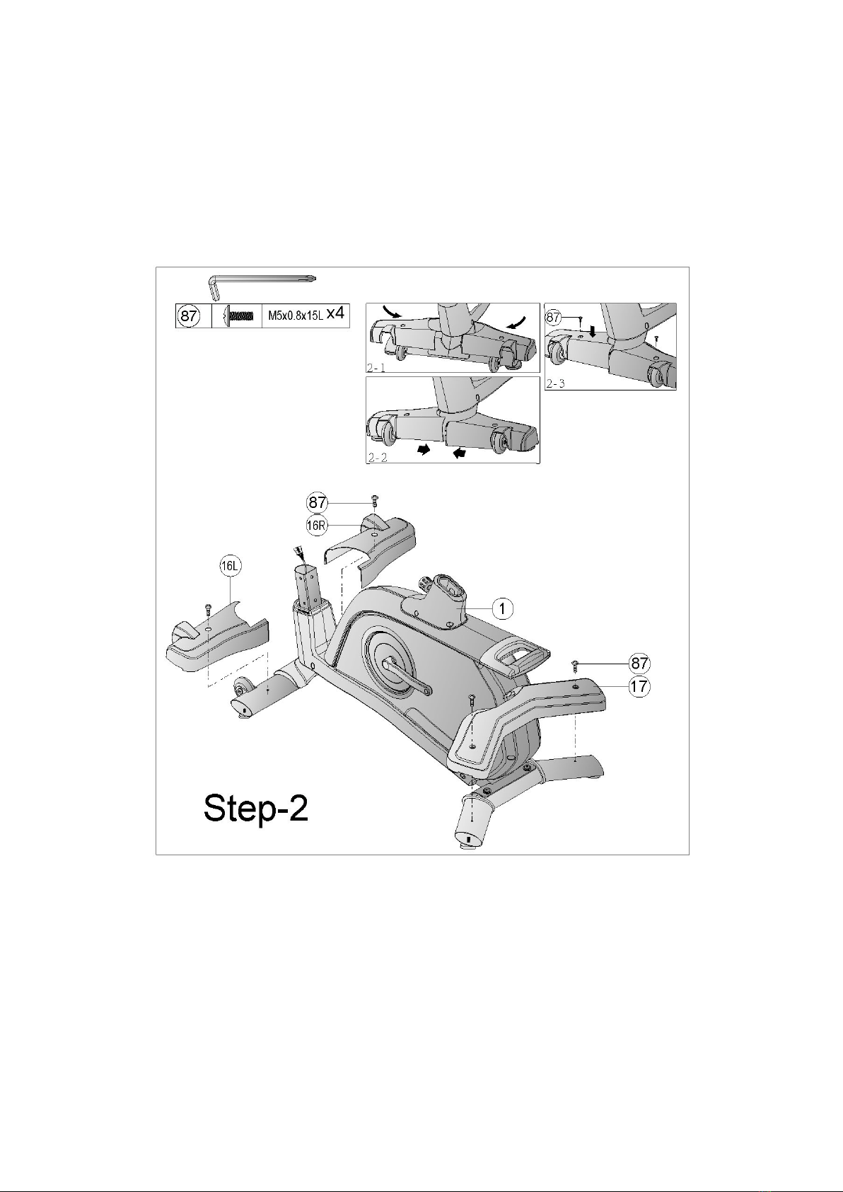
Step 2
1) Assemble the front stabilizer cover (16L&16R) and rear stabilizer cover (17)
onto the front and rear stabilizer by Bolt (87) as fig 2-1,2-2 and 2-3.
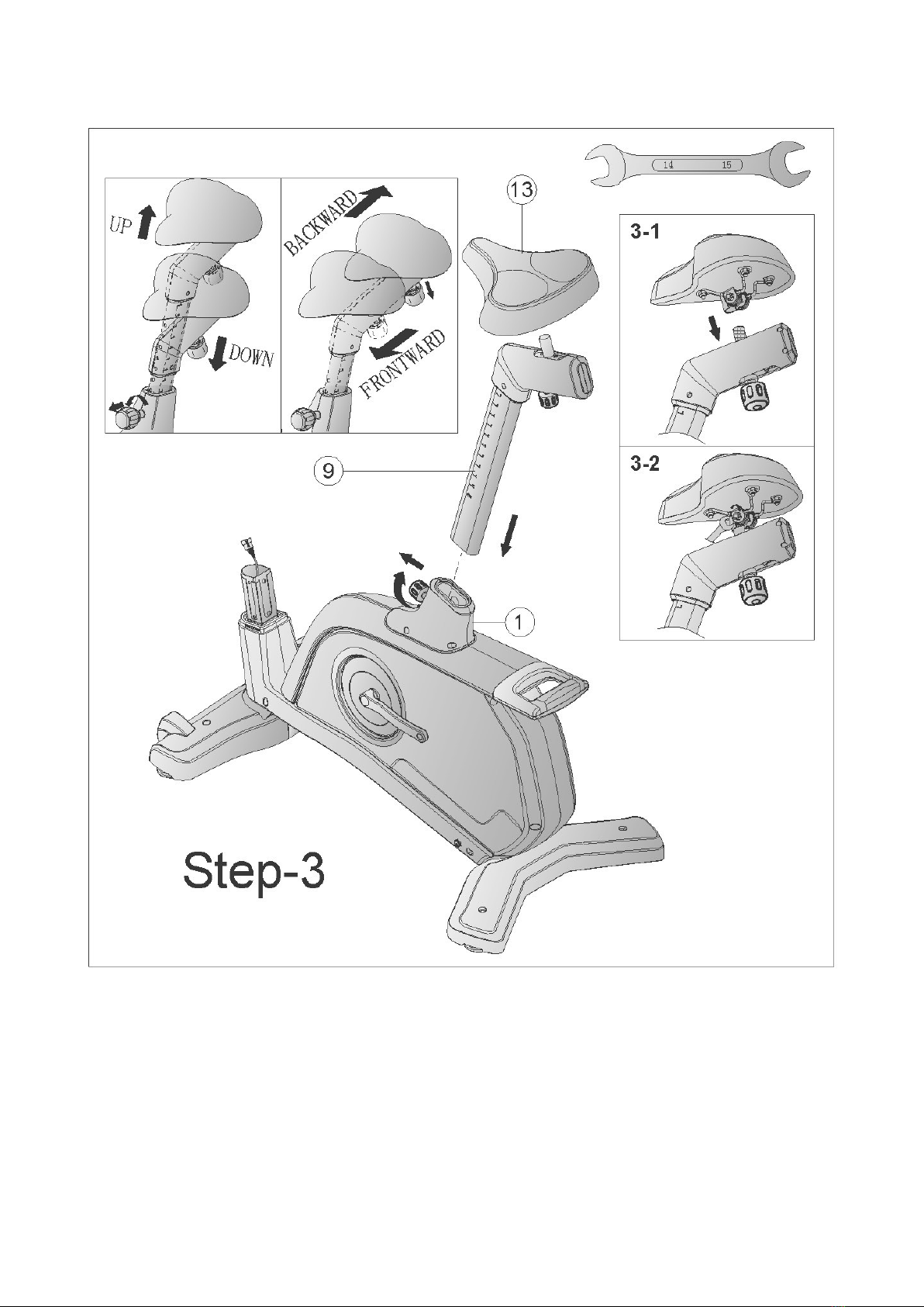
Step 3
1) Insert seat post tube (9) into main frame and adjust the height by knob.
2) Assemble the seat onto the seat adjustment tube as fig 3-1 and 3-2. The seat can be
adjusted frontward and backward by knob
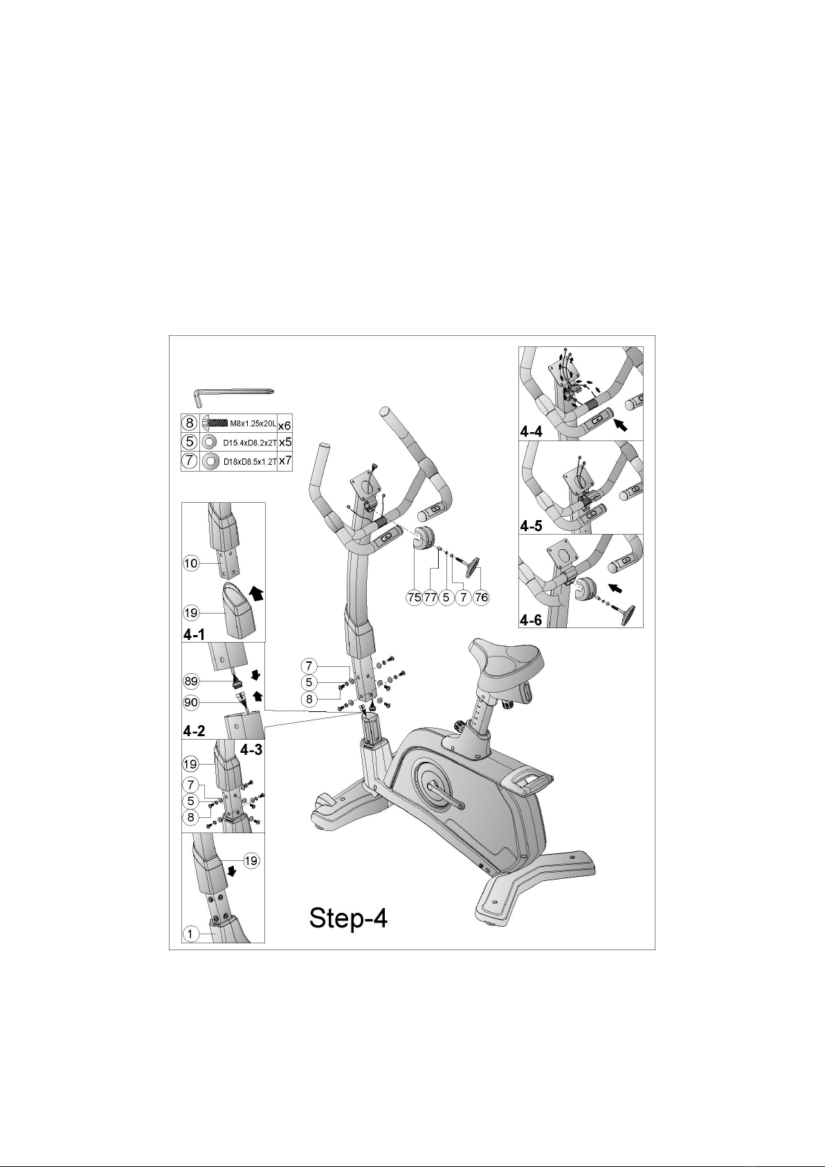
Step 4
1) We suggest assembling this step by two persons.
2) Lift up the upper cover (19) as fig 4-1 and then connect upper and lower computer cable
(89&90) as fig 4-2.
3) Insert the handlebar post (10) into the main frame and tighten it by spring washer (5), flat
washer (7) and Allen bolt (8) as fig 4-3.
4) Through the cable of fixed handlebar out of the handlebar post and then fix the handlebar
by pring washer (5), Flat washer (7), protective cover (75), busing (77) and T knob (76)
as fig 4-4,4-5 and 4-6.
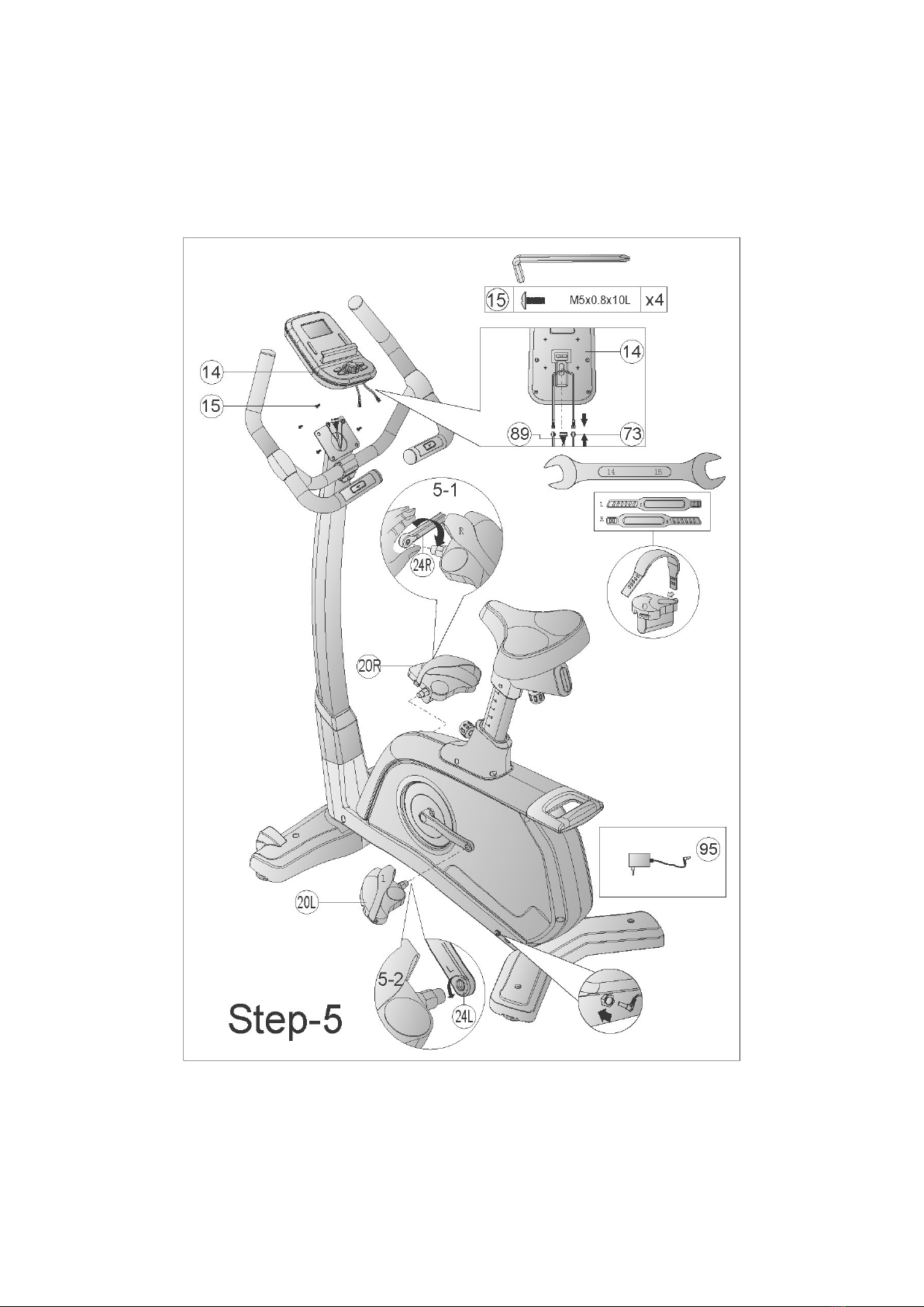
Step 5
1) Connect upper computer cable (89) and Handle pulse cable (73) with cables attached to
the computer (14) and then fix the computer onto the handlebar post by bolt (15).
2) Assemble the pedals (20L&20R) onto crank (24L&24R) as 5-1 and 5-2.
3) Insert the plug of adaptor and turn on the computer.

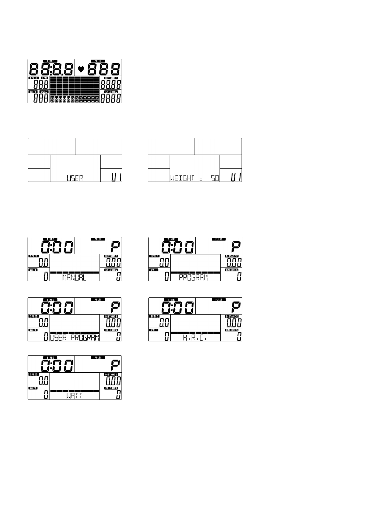
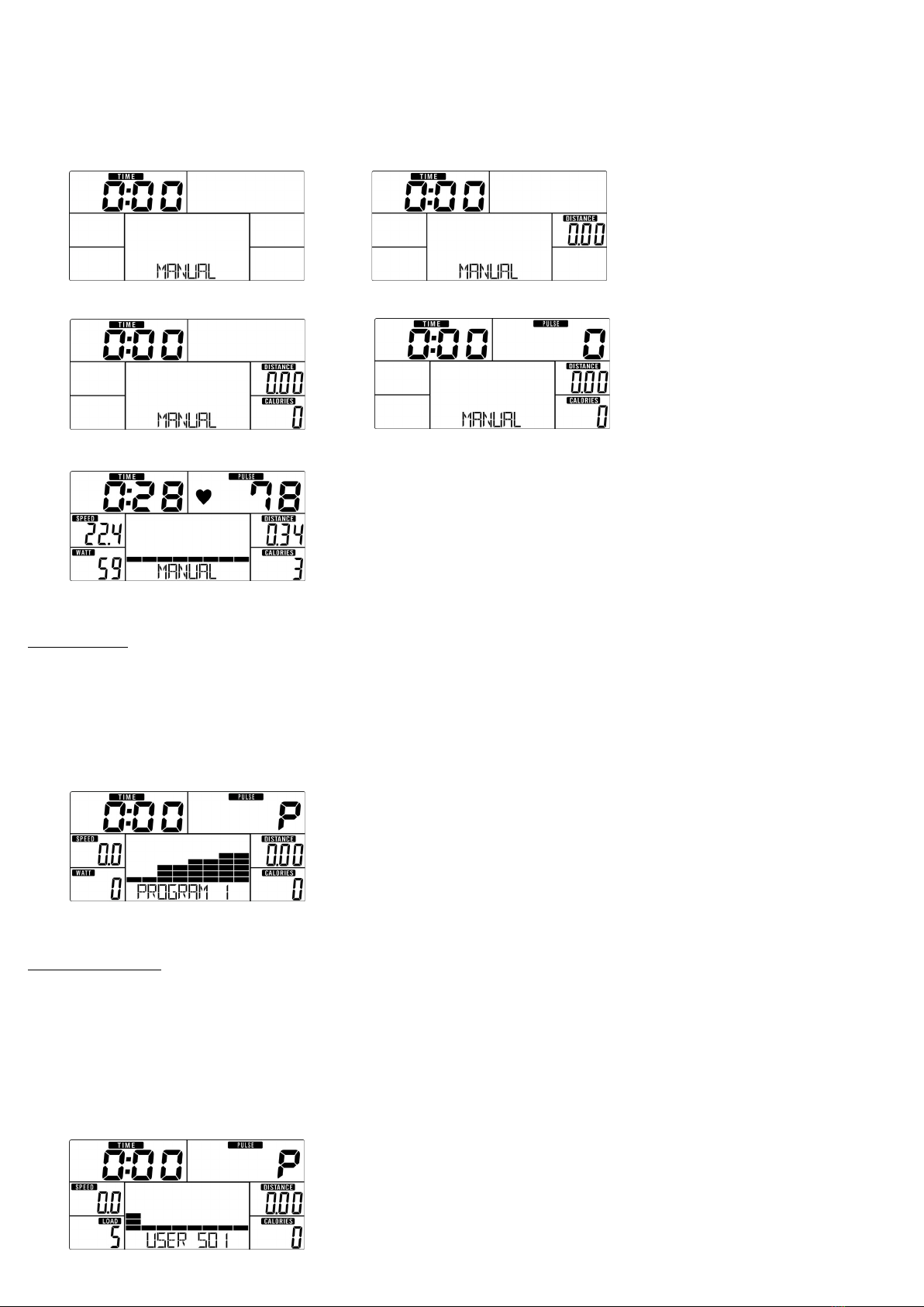
DI PLAY FUNCTION
!!"
#$!#"
%!#&"
'(#")#"*)+,)-+,"
. # " " *) )-" ! (
##&(/0+'12&3" %!#"*))-
&"4""
.5#"
6!#!##7
!!&##"8
/($99:#&;;
&!!<!<#="
'(!>50)"'(4
2=5
>4
23#3<6?49 8
)#="
0>1@>.)5"
/<A"
,>#"
2.#"
!"#$ <
B?5"
!% !"#$ '<
B?5"
!"#&#$ A?5"
#'#& ,##&#?"
><#?=<#"

&($&&! BB="
# !)#$* !<("
+!"*,(& #&#("
-
012%>1
0(##(-'#6'8"
'
!/#?"//0'126%#8/4/6'8!B%C.@%,%@,2%@,6'
98#A&()1'%+%%>&3"2!A!#A"
''9
21>*1/B%-%1
//0'126%#8=)6'806' 8/06'D8,">""6'E8
236'8"
''
'D'E
'
(.(/!"#
0B.>(=#"
" //0'126%#8=!)#)1'%+%%>"
" //0'126%#8)% 6'8'B.%6'8.-1>%B6'80/-B% 6'8 #
)1'%+%%>A"
9" 0B.>+B10=(="//0'126%#8#F#<"-#<#(2.#
#F59!#(2.6'98"
" 0B.>+B10=(="0>%B%<"
''
''
'9
$!0$(1 !"#
" //0'126%#8=!G##)1'%+%%>"
" //0'126%#846'8#)1'%+%%>"
9" //0'126%#8)%"
" 0B.>+B10=(="//0'126%#8#F#<"
" 0B.>+B10=(="0>%B%<"
'
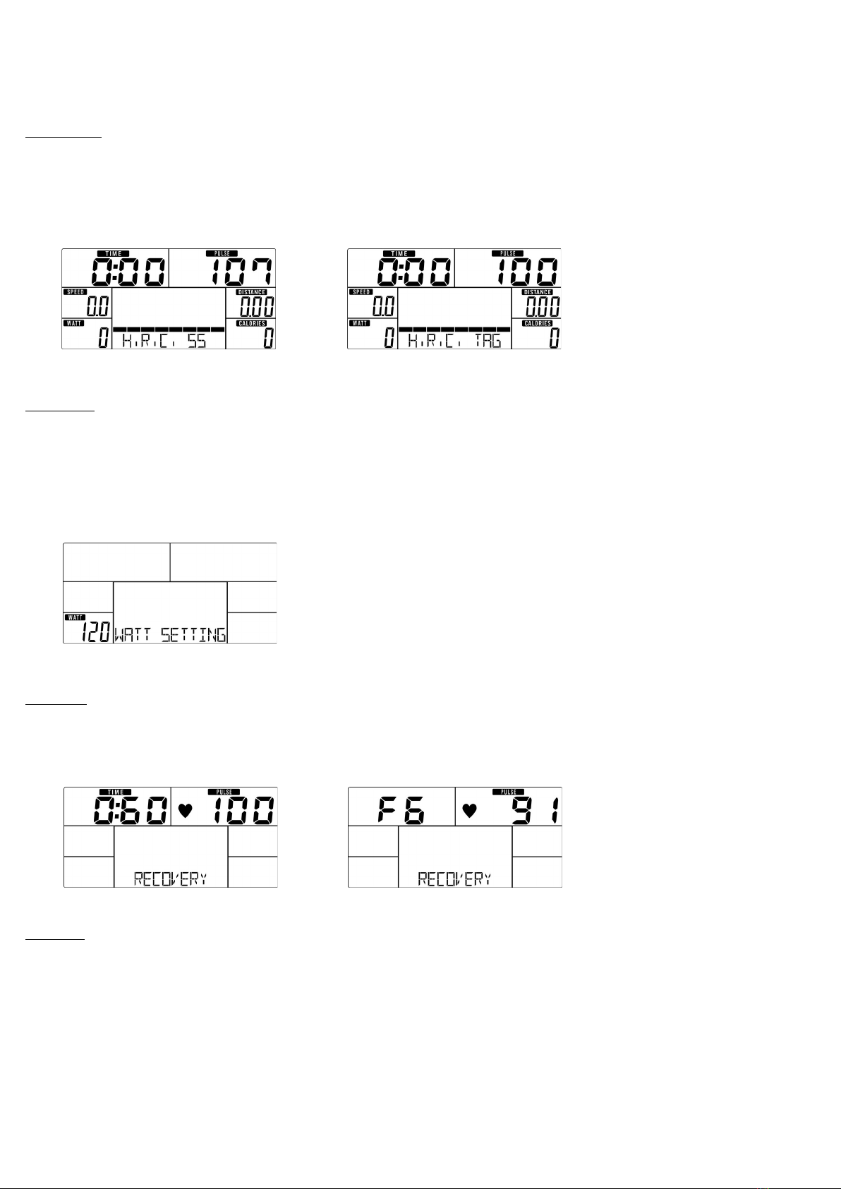
'#$$!0$(1 !"#
" //0'126%#8=!/0##)1'%+%%>"
" //0'126%#8A6' 8"!#F!#<"
/!#)1'%+%%>#H#?"
9" //0'126%#8)%"
" 0B.>+B10=(="//0'126%#8#F#<"
" 0B.>+B10=(="0>%B%<"
'
!"#
" //0'126%#8=!,">""#)1'%+%%>"
" //0'126%#8 I6'D8"E I"I.@6.>@%,">"86#'E8"
9" //0'126%#8=)%"
" 0B.>+B10=(="0>%B%<"
'D'E
(2!"#
" //0'126%#8=!2.#)1'%+%%>"
" //0'126%#82."6#'8
9" //0'126%#8)%"
" 0B.>+B10=(="//0'126%#8#F23<"
" 0B.>+B10=(="0>%B%<"
'
3
.J#=!#!#!#>%1K%>L=(".5#(
M)%N5#D6'8"B#((!<(!!O
O…"OD"O!&OD!6'8"/(=<!!<("60!
>%1K%>L&3!#("8
''
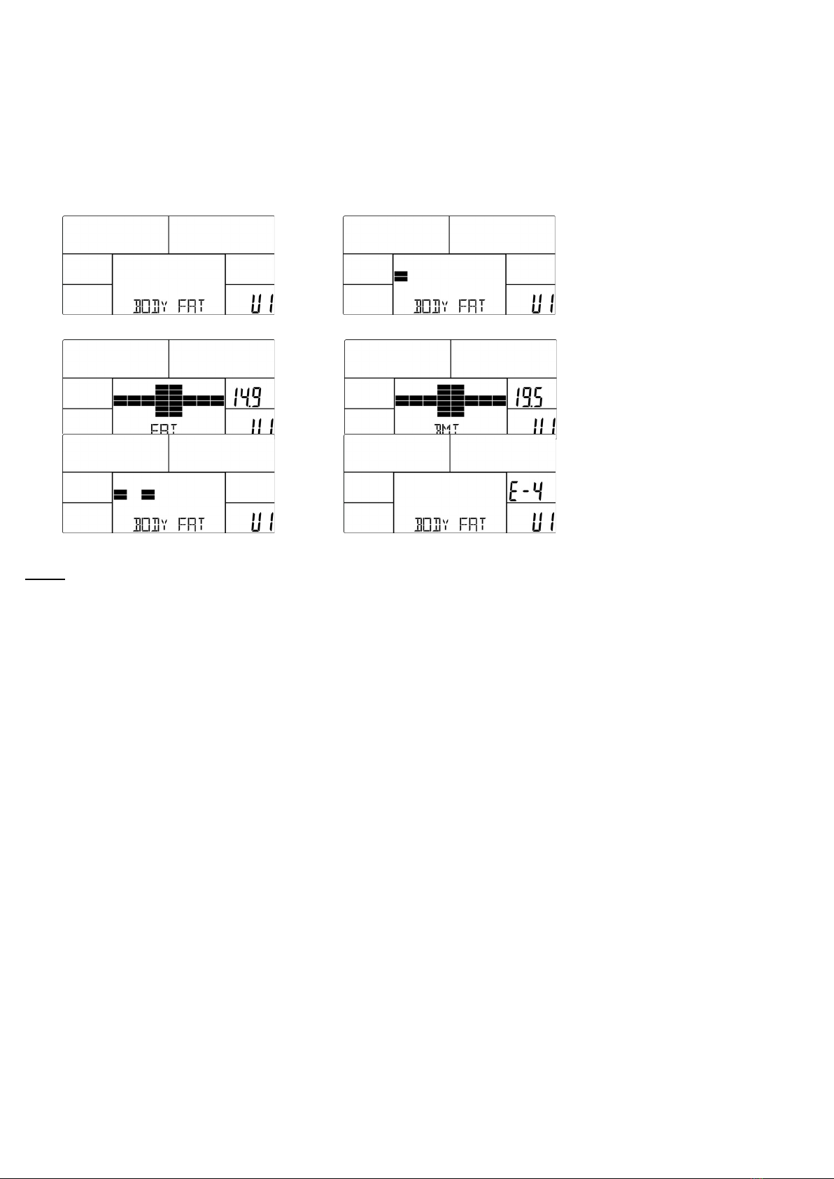
+
" B10#!G1'LO.=(&#(6'8"
" '!<!#&!!#!!#".#!-'#(MPNMPPN6'8#
5A!"
9" -'#(G1'LO.#<(&G1'LO.6'98G)6'89#"
" %
Q!-'#(MPPNMPPN6' 8–!#!!("
Q%$–!!##"
Q%$–1!O.I& # #G)& # 6'D8"
''
'9'
' 'D
!&#"-
".J!#<#"0(=((=!"
"2!&!##"
Table of contents
Other BODYMAX Exercise Bike manuals

BODYMAX
BODYMAX FXB10 User manual

BODYMAX
BODYMAX B50 User manual

BODYMAX
BODYMAX B15 User manual

BODYMAX
BODYMAX B200 User manual

BODYMAX
BODYMAX CVEB2419 User manual

BODYMAX
BODYMAX 40 User manual

BODYMAX
BODYMAX B2 User manual

BODYMAX
BODYMAX CVET2706 User manual

BODYMAX
BODYMAX FXB30 User manual

BODYMAX
BODYMAX RB60 User manual


