Bojin System 3600 User manual

1
MICROTYPE SURGICAL POWER TOOLS
System 3600
Operating manual

2
Index
1 Product introduction Page 3
2 Product classification Page 3
3 Labels and symbols Page 4
4 Indications for use Page 4
5 Dangers and precautions Page 4
6 Technical specification Page 5
6.1 Control unit BJ36006-V Page 5
6.2 Foot pedal BJ36012 Page 7
6.3 Micro-handpiece BJ3600 Page 7
6.4 Bur attachments Page 8
6.5 Craniotomy attachment BJ3605 Page 8
6.6 Sagittal and reciprocating attachments BJ3601 – BJ3609 Page 9
6.7 Dedicated cranial perforator BJ3604 Page 9
7 Instructions for use Page 10
8 Cleaning and sterilization procedure Page 11
9 Fault handling Page 13
10 Electromagnetic Requirements Page 13
11 Transport and storage conditions Page 18
12 Operating conditions Page 18
13 Manufacturing date and period of use Page 19
14 Commitment Page 19

3
Surgical micromotor
1. Product introduction
Description
The device is an electrical surgical product for a wide range of operations for neuro, column and
orthopedics.
Main models and components
Model: BJWJZ-1
Main components: micro-handpiece, straight attachment, angled attachment, sagittal saw
attachment, reciprocating saw attachment, craniotomy attachment, control unit and pedals.
Furthermore, it is also possible to connect a handpiece with classical pistol grip handle (5000
series)
Note: to simplify, angled and straight attacks are collectively called bur attachments
2. Product classification
Based on the classification of the protection against electric shock, the device is considered a
general device belonging to the application part of the Ⅰ BF class.
It cannot be used when the flammable anesthetic gas is mixed with flammable air or narcotic or
mixed with oxygen or nitrous oxide.
Operating system: continuous operation with intermittent loading. Starting from cold, operate for
2 minutes in charging condition. Please stop the continuous use, allowing the device to cool down.
After the break, you can continue the operation.

4
3 Labels and symbols
: type B
Warning. Read the instructions for use. Read the instructions for use
CE Mark Manufacturer
Manufacturing date.
Fuse: T2AL250V
4 Indications for use
Minimally invasive operations, extremity, column, neuro, orthopedic.
5 Dangers and precautions
1.Connect the attachment to the micro handpiece before operating the instrument.
2. The instrument must be sterilized before use.
3. The user must have acquired the technical experience necessary to operate this device.
4. Try the instrument before using it.
a) Burs and saw blades must be securely fastened to the device in a safe manner. No vibrations
Colibri II Istruzioni per l’uso DePuy Synthes 5
SM_109761
Li-Ion
Questo dispositivo contiene batterie Li-Ion
che devono essere smaltite in modo ecolo-
gico. A questo dispositivo si applica la diret-
tiva europea sulle batterie 2006/66/CE. Vedi
capitolo «Smaltimento» a pagina 47 .
2
Non riutilizzare
I prodotti monouso non devono essere riuti-
lizzati.
Il riutilizzo o la rigenerazione (p. es. pulizia e
sterilizzazione) possono compromettere l’in-
tegrità strutturale e/o causare il malfunziona-
mento del dispositivo, provocando lesioni,
malattia o causando la morte del paziente.
Inoltre, il riutilizzo o la rigenerazione di un
dispositivomonousopuògenerareilrischio
di contaminazione, p. es. a causa di trasmis-
sione di materiale infettivo da un paziente
all’altro.Ciòpuòprovocarelesioniomorte
del paziente o dell’utente.
Synthes consiglia di non rigenerare i prodotti
contaminati. Ogni prodotto Synthes contami-
natodasangue,tessutie/ouidi/materiali
corporei non deve essere riutilizzato e deve
essere maneggiato in conformità alle diret-
tive ospedaliere.
Anche se possono sembrare integri, i pro-
dotti possono presentare piccoli difetti o
avere subito solle citazioni interne con conse-
guente indebolimento del materiale.
Temperatura
Umidità relativa
Spiegazione dei simboli generali usati
Attenzione
Leggere le Istruzioni per l’uso fornite prima
di usare il dispositivo.
Consultare le Istruzioni per l’uso fornite
prima di usare il dispositivo.
L’apparecchioèstatoclassicatocomedispo-
sitivo di classe BF in relazione a folgorazioni
elettriche e correnti di dispersione. L’apparec-
chio è adatto per essere utilizzato sui pa-
zientiaisensidelledirettivedenitedaCSA
601.1, IEC 60601-1 e UL 60601. IEC 60601-
1:2005, ANSI/A AMI ES60601-1 (2005), CAN/
CSA-C22.2 No. 60601-1 (2008)
SM_109761
Non immergere il dispositivo in liquidi.
10PB
In relazione a folgorazioni elettriche, incen-
dio, pericoli meccanici solo in conformità a
EN 60601-1 e ANSI/AAMI ES60601-1 (2005)
e CAN/CSA C22.2 N. 60601.1 (2008).
Questo dispositivo è conforme ai requisiti
della direttiva 93/42/CEE per i dispositivi me-
dici.E’statoautorizzatodaunorganonoti-
cato esterno e pertanto riporta il simbolo CE.
Precauzione: Rischio di fuoco, esplosione e ustioni.
Non smontare, frantumare, scaldare a temperatura
superiore a 60 °C/140 °F o incenerire le celle della
batteria.
Colibri II Istruzioni per l’uso DePuy Synthes 5
SM_109761
Li-Ion
Questo dispositivo contiene batterie Li-Ion
che devono essere smaltite in modo ecolo-
gico. A questo dispositivo si applica la diret-
tiva europea sulle batterie 2006/66/CE. Vedi
capitolo «Smaltimento» a pagina 47 .
2
Non riutilizzare
I prodotti monouso non devono essere riuti-
lizzati.
Il riutilizzo o la rigenerazione (p. es. pulizia e
sterilizzazione) possono compromettere l’in-
tegrità strutturale e/o causare il malfunziona-
mento del dispositivo, provocando lesioni,
malattia o causando la morte del paziente.
Inoltre, il riutilizzo o la rigenerazione di un
dispositivomonousopuògenerareilrischio
di contaminazione, p. es. a causa di trasmis-
sione di materiale infettivo da un paziente
all’altro.Ciòpuòprovocarelesioniomorte
del paziente o dell’utente.
Synthes consiglia di non rigenerare i prodotti
contaminati. Ogni prodotto Synthes contami-
natodasangue,tessutie/ouidi/materiali
corporei non deve essere riutilizzato e deve
essere maneggiato in conformità alle diret-
tive ospedaliere.
Anche se possono sembrare integri, i pro-
dotti possono presentare piccoli difetti o
avere subito solle citazioni interne con conse-
guente indebolimento del materiale.
Temperatura
Umidità relativa
Spiegazione dei simboli generali usati
Attenzione
Leggere le Istruzioni per l’uso fornite prima
di usare il dispositivo.
Consultare le Istruzioni per l’uso fornite
prima di usare il dispositivo.
L’apparecchioèstatoclassicatocomedispo-
sitivo di classe BF in relazione a folgorazioni
elettriche e correnti di dispersione. L’apparec-
chio è adatto per essere utilizzato sui pa-
zientiaisensidelledirettivedenitedaCSA
601.1, IEC 60601-1 e UL 60601. IEC 60601-
1:2005, ANSI /A AMI ES60601-1 (2005), CAN/
CSA-C22.2 No. 60601-1 (2008)
SM_109761
Non immergere il dispositivo in liquidi.
10PB
In relazione a folgorazioni elettriche, incen-
dio, pericoli meccanici solo in conformità a
EN 60601-1 e ANSI/AAMI ES60601-1 (2005)
e CAN/CSA C22.2 N. 60601.1 (2008).
Questo dispositivo è conforme ai requisiti
della direttiva 93/42/CEE per i dispositivi me-
dici.E’statoautorizzatodaunorganonoti-
cato esterno e pertanto riporta il simbolo CE.
Precauzione: Rischio di fuoco, esplosione e ustioni.
Non smontare, frantumare, scaldare a temperatura
superiore a 60 °C/140 °F o incenerire le celle della
batteria.
6 DePuy Synthes Colibri II Istruzioni per l’uso
Introduzione
Informazioni generali
Pressione atmosferica
S9 Tipo di ciclo di funzionamento conforme alla
norma CEI 60034-1
IPX4 Grado di protezione ingresso conforme alla
norma CEI 60529
Data di fabbricazione e produttore
Data di fabbricazione
non sterile Non sterile
Non sterile
Non utilizzare se la confezione è
danneggiata.
5
should be visible from attachments or cutting tools. Check the radial movement of the tips. Do not
use if the radial movement is too wide. Check if the cutter is sharp, if it is not sharp enough, it must
be replaced in time.
b) If the bur breaks, replace it immediately.
c) The bur is a consumable product and its duration is generally 10 uses.
d) The control unit has a short-circuit protection device. When a short circuit fault occurs, the
device automatically interrupts the output power.
e) After the product has completed its life cycle, please dispose of it according to the relevant
regulations.
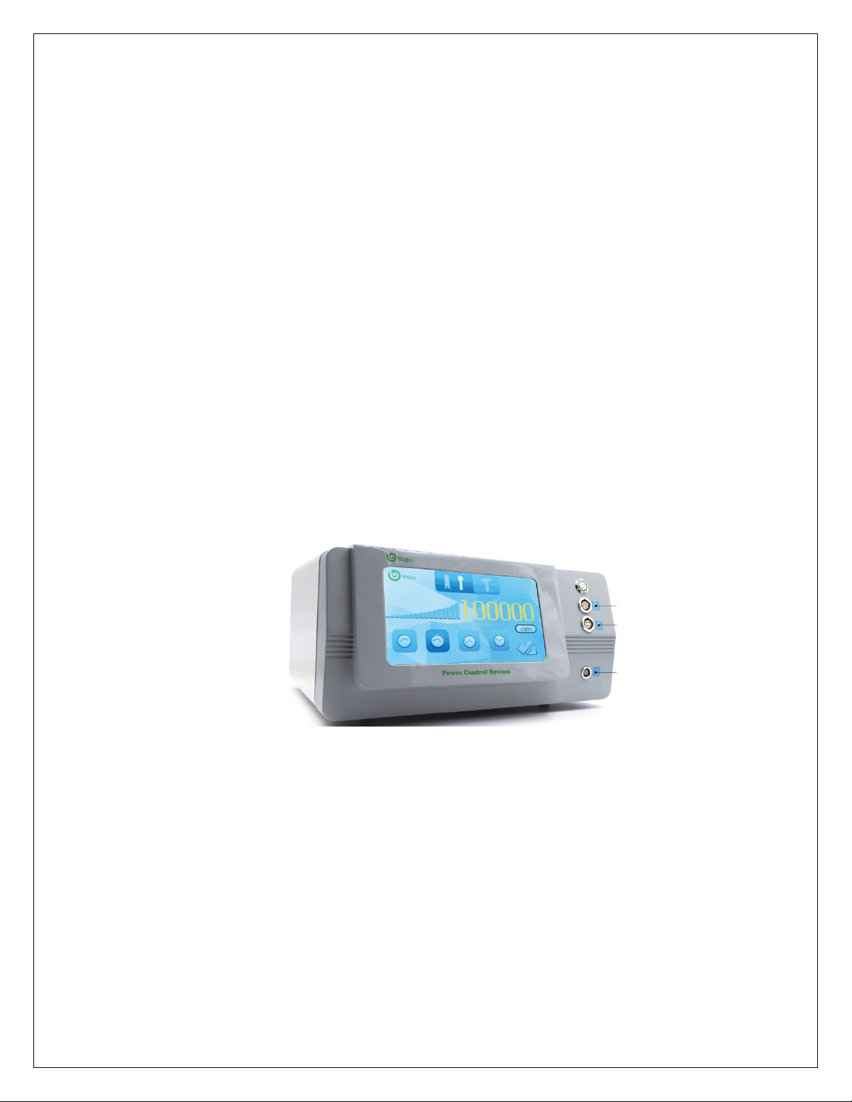
6 Technical specification
6.1 Control unit BJ36006-V
1. Power supply: AC 110V/220V 50HZ
2. Input power: 450VA
Image: Control unit BJ36006-V

6
1. Button for switching on / off
2. Connection port for micro-handpiece BJ3600
3. Connection port for BJ5000 series handgun modular gun, or dedicated handpiece for cranial
drilling BJ3604
4. Connection port for BJ36012 pedal board
5. On-screen button to choose between activation by footswitch or by screen
6. Direction of rotation
7. Increase and decrease speed (indication of same on screen in rpm)
8. Blade mode (for micro-handpiece BJ3600)
9. Milling (bur) mode (for micro-handpiece BJ3600)
10. Cranial perforator mode (for dedicated BJ3604 handpiece)
7
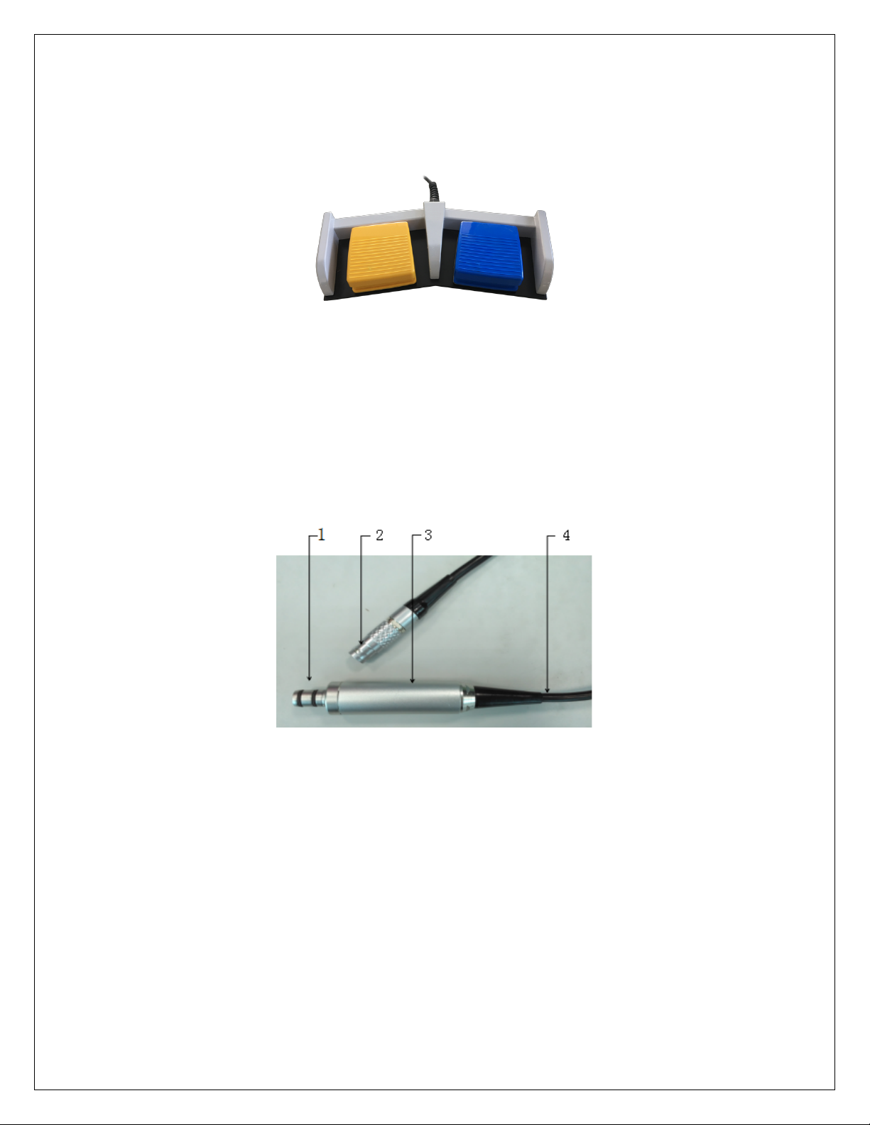
6.2 Foot pedal BJ36012
Image: Foot pedal BJ36012
Cable: 3 meters
Water resistant IPX6
6.3 Micro-handpiece BJ3600
Input voltage: DC 12V
Output power: ≥100W
Noise: <65dB
Image: Micro-handpiece BJ3600
1. Handpiece connector
2. Motor control connector
3. Handpiece
3. Cable
8
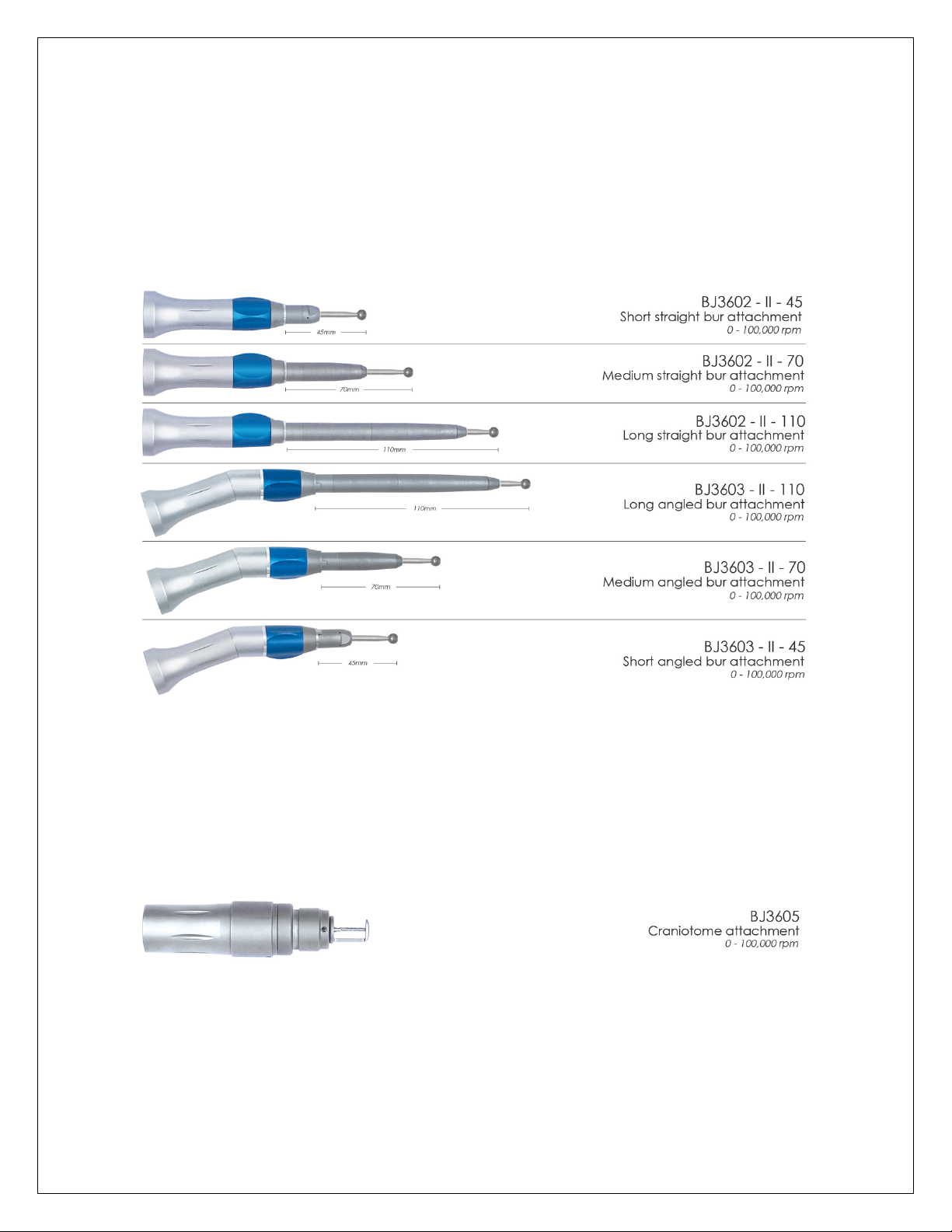
6.4 Bur attachments
Speed: 1000rpm-100000rpm
Error:±8%
Torque: 0.10 Nm
Connection type: standard round shank 2,35mm
6.5 Craniotomy attachment BJ3605
Speed: 1000rpm-100000rpm
Error:±8%
Torque: 0.10 Nm

9
6.6 Sagittal and reciprocating attachments BJ3601 – BJ3609
Speed: 1000rpm-15000rpm
Error:±8%
Connection type for sagittal saw blades: code BJ3501
Connection type for reciprocating saw blades: code WF
6.7 Dedicated cranial perforator BJ3604
Speed: 100rpm - 1100rpm
Torque: 2.24Nm
Connection type for cranial drill bit: code BJP007

10
NOTE: THIS USER MANUAL WILL FOCUS ON THE USE OF THE CONTROL UNIT WITH THE BJ3600 HIGH-SPEED
MICRO-HANDPIECE. FOR THE INSTRUCTIONS FOR USING THE BJ5000 SERIES, REFER TO THE MANUAL FOR USE OF THE
SAME SERIES.
7 Instructions for use
1. Connect the electric cable to the instrument console, the light indicator indicates the power on and by pressing the
start key, the monitor indicates the icons of the different and optional operations.
2. Once activated, the instrument shows the PEDAL mode and shows the minimum operating speed; the MANUAL mode
is not shown with the icon.
3. In the pedal control mode, the screen rotation change buttons are not accessible. Press the speed button to change it,
setting the maximum reachable. By pressing the pedal, the rotary speed of the motor increases linearly from the lowest
point to the highest point that was previously set.
4. In manual control mode, press the activation button. Manual control mode is shown with the button icon. The pedal
switch is not accessible. Then, adjust the parameters on the control panel to set the speed and direction of the motor,
press the manual control mode activation button again, the motor will run in the current speed and direction.
5. When the instrument is not in use, please disconnect the power cord.
Note:
• After following the instructions, now described, please pay attention that there are no noises or imperfections of the
instrument.
• In manual control mode, do not touch the pedal control mode activation button, otherwise it will turn into the pedal
control mode.
• Depending on the different surgical needs, it is possible to select different drill attachments (straight or angled) and
insert boring bits. To lock the cutter, insert it up to the bottom with the locking system in the open position. Once the
cutter is inserted, rotate the locking system in the opposite direction. To make sure that the cutter is firm, pull it slightly.
• To connect the sagittal blade, press the button on the attachment. Keeping the same pressed, insert the blade and
make the holes of the blade correspond with the teeth of the locking system. Once the connection has been made,
release the button and check that the blade is firmly in place by pulling it slightly.
• To connect the blade to each other, rotate the locking system and align the blade inlet line. Insert the blade, as the
locking system rotates. Once the blade is inserted, release the rotating part. Check that the blade is firm, pulling it
slightly.

11
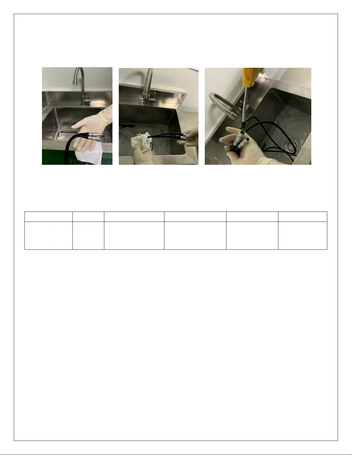
8 Cleaning and sterilization procedure
The devices must be cleaned and sterilized before each use. Use protective equipment every time even such operations
are performed.
Use a neutral pH detergent, not exceeding 10.5. Fill the sink with water and detergent, mix gently by hand. Before
cleaning the device, remove all accessories, battery connections and shells. Rinse the device under warm running water
(between 27 ° C and 44 ° C) using a soft, lint-free cloth and a soft bristle brush. Remove coarse dirt. Be careful to move
all moving parts, such as triggers, bushings and selectors under running water to remove debris. Do not use sharp
objects.
Never immerse the devices in an aqueous solution or in an ultrasonic bath. Also, do not allow moisture to remain inside
the cannulated parts, in the selectors or in the electrical connection areas. Do not rinse the handpiece from the front or
use pressurized water to avoid damaging the system.
Use a soft brush with a diameter suitable for the cannulated part to clean it. Pay attention that the brush passes through
the total length of the affected area. Move all the moving parts to clean the residual debris. Keep the device tilted, with
the head pointing downwards, under running water. Be careful to completely remove the detergent under running
water.
Visually inspect the device, including cannulations to check for traces of dirt. If present, repeat the previous steps. I
would place inclined devices on absorbent cloths to dry them. Or use compressed air (medical use).
To clean a connection cable, hold it by both ends and clean the cable using a soft cloth dampened with detergent. Finally
dry with compressed air.
12
.
When sterilizing, perform the following sterilization cycle validated by Bojin to obtain optimum performance. Steam
sterilization
Wrapping method
Cycle
Minimum temperature
Maximum Temperature
Minimum Exposure
Minimum dry time
Wrapped
Pre-vacuum
129°C
134°C
4 minutes
8 minutes
Note: The Operator must ensure that the affected parts have been sterilized, before use.

13
9 Fault handling
Maintenance
For safety reasons, electrical microsurgery devices must be inspected once a year. For
maintenance operations, please contact your dealer or contact the Bojin after-sales service directly
for maintenance, performed by the instrument's experts.
Removing the problem
The device is equipped with short-circuit protection. In case of connection or other abnormal use
of the pause button, please restart the power supply and check if this returns the instruments to
normal functionality. If the problem is not resolved, contact the after-sales service for the
maintenance of the instruments.
Repair of the problem
In addition to the fuse, the equipment contains no repairable parts inside, so do not attempt to
open the enclosure, the foot switch, the control box and other components. If other problems
persist, contact the after-sales service for instrument maintenance.
For maintenance performed by skilled and qualified figures, please turn off the power switch,
check if the fuse is blown. If it is, replace it with the one from the T2AL250V specifications.
10 Electromagnetic Requirements
Operation is subject to the following two conditions: (1) This device may not cause harmful
interference, and (2) this device must accept any interference received, including interference that
may cause undesired operation.
Use of accessories other than those recommended may result in non-compliance with
electromagnetic compatibility and immunity standards.
Guidance and Manufacturer’s Declaration - Electromagnetic Emissions

14
3600 Handpieces are intended for use in the electromagnetic environment specified below.
The customer or the user of the 3600 Handpieces should assure that they are used in such
an environment
Emissions test
Complian
ce
Electromagnetic environment - guidance
RF Emissions CISPR 11
Group 1
The 3600 Handpieces use RF energy only for
internal functions; therefore, RF emissions are
very low and are not likely to cause any
interference in nearby electronic equipment.
RF Emissions CISPR 11
Class A
The 3600 Handpieces are intended for use by
healthcare professionals only and is suitable for
use in all establishments other than domestic
and those directly connected to the public
low-voltage power supply network that supplies
buildings used for domestic purposes.
Harmonic Emissions IEC
61000-3-2
N/A
Not Applicable
Voltage Fluctuations/Flicker
Emissions IEC 61000-3-3
N/A
Not Applicable

15
Guidance and Manufacturer’s Declaration - Electromagnetic Immunity
The 3600 Handpieces are intended for use in the electromagnetic environment specified
below. The customer or the user of the 3600 Handpieces should assure that it is used in
such an environment.
Immunity Test
IEC 60601
Test Level
Compliance Level
Electromagnetic
Environment
Guidance
Electrostatic
discharge (ESD) IEC
61000-4-2
± 6 kV contact
± 8 kV air
± 6 kV contact
± 8 kV air
Floors should be
wood, concrete or
ceramic tile. If floors
are covered with
synthetic material,
the relative humidity
should be at least
30%.
Electrical fast
± 2 kV for power
supply lines
± 2 kV for power
supply lines
Mains power quality
should
transients/bursts
be that of a typical
IEC 61000-4-4
± 1 kV for
input/output lines
± 1 kV for
input/output lines
commercial or
hospital
environment.
Surge
± 1 kV line to line
± 1 kV line to line
Mains power quality
should
IEC 61000-4-5
be that of a typical
± 2 kV lines to earth
± 2 kV lines to earth
commercial or
hospital
environment.
Power frequency
(50/60 Hz)
magnetic field
IEC 61000-4-8
3 A/m
3 A/m
Power frequency
magnetic fields
should be at levels
characteristic of a
typical location in a
typical commercial or
hospital
environment.

16
Voltage dips, short
interruptions and
voltage variations
on power supply
<5% Ut (>95% dip in
Ut)
for 0.5 cycle
<5% Ut (>95% dip in
Ut)
for 0.5 cycle
Mains power quality
should be that of a
typical commercial or
hospital
input lines
IEC 61000-4-11
40% Ut (60% dip in
Ut)
for 5 cycles
40% Ut (60% dip in
Ut)
for 5 cycles
environment. If the
user of the 3600
Handpieces requires
continued operation
70% Ut (30% dip in
Ut)
for 25 cycles
70% Ut (30% dip in
Ut)
for 25 cycles
during power mains
interruptions, it is
recommended that
the 3600
<5% Ut (>95% dip in
Ut)
for 5 seconds
<5% Ut (>95% dip in
Ut)
for 5 seconds
Handpieces be
powered from an
uninterruptable
power supply or
battery.
NOTE: Ut is the a.c. mains voltage prior to application of the test level.
Portable and mobile RF communications equipment should be no closer to any part of the
3600 Handpieces, including cables, than the recommended separation distance calculated
from the equation applicable to the frequency of the transmitter.

17
Guidance and Manufacturer’s Declaration - Electromagnetic Immunity (Continued)
The 3600 Handpieces are intended for use in the electromagnetic environment specified
below. The customer or the user of the 3600 Handpieces should assure that it is used in
such an environment.
Immunity Test
IEC 60601
Test Level
Compliance Level
Electromagnetic
Environment
Guidance
Conducted RF IEC
61000-4-6
150 kHz to 80 MHz
3 Vrms
Recommended
Separation Distance
d = 1.2 √ P
Radiated RF
IEC 61000-4-3
80 MHz to 2.5 GHz
3 V/m
d = 1.2 √ P 80 MHz to
800 MHz
d = 2.3 √ P 800 MHz
to 2.5 GHz
Where P is the maximum output where P is the maximum output power rating of the
transmitter in watts (W) according to the transmitter manufacturer and d is the
recommended separation distance in meters (m). Field strengths from fixed RF transmitters,
as determined by an electromagnetic site survey a, should be less than the compliance level
in each frequency range b.
Interference may occur near the equipment marked with the following symbol:
NOTE 1: At 80 MHz and 800 MHz, the higher frequency range applies.
NOTE 2: These guidelines may not apply in all situations. Electromagnetic propagation is
affected by absorption and reflection from structures, objects, and/or people.
a.
Field strengths from fixed transmitters, such as base stations for radio (cellular/cordless)
telephones and land mobile radios, amateur radio, AM and FM radio broadcast and TV
broadcast cannot be predicted theoretically with accuracy. To assess the electromagnetic
environment due to fixed RF transmitters, an electromagnetic site survey should be
considered. If the measured field strength in the location in which the 3600 Handpieces is
used exceeds the applicable RF compliance level above, 3600 Handpieces should be
observed to verify normal operation. If abnormal performance is observed, additional
measures may be necessary, such as re-orienting or relocating the 3600 Handpieces.
b.
Over the frequency range 150 kHz to 80 MHz, field strengths should be less than 3 V/m.

Recommended Separation Distances Between Portable and Mobile RF Communications
Equipment and the 3600 Handpieces @ 3Vrms
3600 Handpieces are intended for use in an electromagnetic environment in which radiated
RF disturbances are controlled. The customer or the user of 3600 Handpieces can help
prevent electromagnetic interference by maintaining a minimum distance between
portable and mobile RF communications equipment (transmitters) and the 3600
Handpieces as recommended below, according to the maximum output power of the
communications equipment.
Separation Distance According to Frequency of Transmitter (meters)
Rated Maximum
Output Power of
Transmitter
(Watts)
m
150 kHz to 80
MHz
d 3.5 P
v1
80 MHz to 800 MHz
d 3.5 P
E
1
800 MHz to 2.5 GHz
d 7 P
E
1
0.01
0.12
0.12
0.23
0.1
0.34
0.34
0.74
1
1.7
1.7
2.3
10
3.7
3.7
7.4
100
11.7
11.7
23.3
For transmitters rated at a maximum output power not listed above, the recommended
separation distances d in meters (m) can be estimated using the equation applicable to the
frequency of the transmitter, where P is the maximum output power rating of the transmitter
in watts (W) according to the transmitter manufacturer.
Note 1: At 80 MHz and 800 MHz, the separation distance for the higher frequency range
applies.
Note 2: These guidelines may not apply in all situations. Electromagnetic propagation is
affected by absorption and reflection from structures, objects, and people.
11 Transport and storage conditions
1.ambient temperature range: -10℃~40℃
2.relative humidity range: ≤90%
3.Kpa: 500hPa~1060hPa
12 Operating conditions
normal working conditions:
ambient temperature:5 ℃~35℃
relative humidity:35%~75%
Kpa: 860hPa~1060hPa
Supply voltage:AC 110V/220V,tolerance±10%;frequency:50Hz,tolerance±1Hz
motor power:(DC)12 V
There is no conductive dust, explosive gas, and corrosive gases

19
13 Manufacturing date and period of use
Production date: see label
Duration: 5 years
14 Commitment
A) This device has no removable parts for non-professional personnel, in case of failure,
please contact the after-sales service.
B) If you need technical information (such as circuit diagram, list of components, illustrations,
correction details, etc.) you can request it at the Technical Assistance Center.
Shanghai Bojin Electric Instrument & Device Co., Ltd. Bojin Europe srls
Add: Room 606, No. 3388, Gonghexin Road, Shanghai City. China,200436 Via Ortana 20, Vitorchiano 01030
Web: http://www.bojin-medical.com Italy
Tel: 0086 21 66308078 eurosales@bojin-medical.com
Fax: 0086 21 66527013
This manual suits for next models
1
Table of contents


