BOLERO SEAP-12-800 Specification sheet

Models:
SEAP-12-800 & SEAP-24-1K0
OPERATION AND INSTALLATION MANUAL
Contents
Page 1 Contents
Page 2 Introduction and General
Information
Page 3 Warranty
Page 4 Pre Installation Information
Electrical Requirements
Page 5 Installation / AC Wiring
Page 6 DC Wiring
Page 7 Start Up Procedure
Page 8 Controls and Display
Load Sense Feature and Adjustment
Page 9 Adjusting Load Sensitivity
Troubleshooting
Page 10 How long will my battery last?
Page 11 Technical Data
Page 12 Mounting Specifications
Solar Energy Australia Pty Ltd ACN 081 639 038
Sydney: 4 Beaumont Road. Mt Kuring Gai NSW 2080 Tel 02 9457 2277 Fax 02 9457 2255
Melbourne: 1/15 Nicole Close, North Bayswater, VIC 3153 Tel 03 9761 5877 Fax 03 9761 7789
Introduction and General Information
BOLERO
High Performance Sinewave
Inverter

Solar Energy Australia
Doc No SPN-1601A Rev0803 Page 2
Bolero Manual
Thank you for choosing to purchase another quality inverter from Solar Energy Australia. This product has been developed to
provide you with years of trouble free operation. Your SEA inverter provides True Sinewave output with power quality and
voltage regulation equal to or better than grid electricity.
It is important to us that you get the best out of your inverter, so please take a few minutes to read this manual carefully, it could
save you from frustration. If you have any comments regarding our products and / or service, please do not hesitate to contact us
to discuss your thoughts.
Remember: As soon as your Solar Energy Australia inverter has been installed please complete and return your warranty card.
This will enable us to efficiently handle any service enquiries you may have, and keep you updated with any relevant important
updates.
Features Include:
• True sinewave at 50Hz
• Total harmonic distortion (THD) <2.0%
• High surge capacity
• Extremely High overall efficiency
• Intelligent overload control
• Short circuit protection
• Quick response stand-by function
• Dynamic battery low voltage control
• Designed for harsh climatic conditions
• Manufactured in SMD-technology
• Aluminium base with steel cover
• Integrated DC circuit breaker
• 35mm sq battery cables
• AC & DC EMC attenuation.
• M.E.N Compatible

Solar Energy Australia
Doc No SPN-1601A Rev0803 Page 3
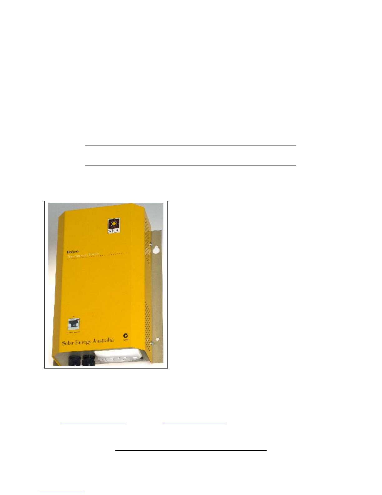
Bolero Manual
WARRANTY – TERMS AND CONDITIONS
Solar Energy Australia considers reliability of your power system/inverter as absolutely critical. We would rather avoid any potential
inconvenience by being proactive. Many external influences can effect the reliability of an inverter, none of which are under the control of
Solar Energy Australia. For these reasons we request that you register your warranty within 60 days of purchase. Warranties which are not
registered receive a 6 month warranty.
These terms and conditions do not exclude your rights under the statutory or implied warranty within your state or territory.
Solar Energy Australia warrants this inverter against defects in material or workmanship, for a period of two (2) years from the date of purchase
when in normal use and service. The warranty period will provide a total of two (2) years if a completed warranty card is received within 60 days
of purchase. No warranty will be provided on units which have not been paid for in full.
This warranty does not extend to products which have been opened, altered or repaired by persons other than those authorised by Solar Energy
Australia or to products which become defective due to acts of God, fire, sabotage, vandalism, contaminated fluids, negligence or failure to
operate, house and maintain the product in accordance with instructions provided in this manual. It is extremely important that all installation
instructions contained within this manual are strictly adhered to. Failure to do so will void your warranty.
Units which are to be permanently used within 1km of the coast should have the marine version of our product, this will help to avoid
corrosion problems which are not covered under the terms of this warranty.
Except for the foregoing expressed warranty, Solar Energy Australia makes no other warranty, expressed or implied, including but not limited to,
the warranty of merchantability or fitness for a particular purpose.
Solar Energy Australia will repair or replace the defective product in accordance with its best judgement. For service under warranty, the buyer
must contact Solar Energy Australia to obtain a “Return Materials Advise” (RMA) document and shipping instructions before returning the unit.
Products returned without prior authorisation may be delayed. The buyer will pay all charges incurred in returning the product to the factory,
including any charges incurred for the uninstallation or reinstallation of the inverter and / or its system components. Solar Energy Australia will
pay return freight charges, if the product is found to be defective, within the terms of this warranty. Repair or replacement of any unit does not
extend the original warranty terms in any way.
This warranty does not cover repairs made necessary due to the product coming in contact with dirt, abrasives, moisture, erosion, corrosion,
varnish or other similar, or failure due to poor quality or poor condition of batteries or other system components, or back feed from another AC
source.
Suitably qualified personnel MUST carry out wiring. Failure to do so cannot justify a warranty claim.
If you have any questions about this warranty please do not hesitate to contact us.

Solar Energy Australia
Doc No SPN-1601A Rev0803 Page 4
Bolero Manual
Pre Installation Information
Batteries
Before installing your Sine Wave Inverter, it is important that you have appropriately sized batteries. A battery that is too small
will not allow the inverter to perform to its full specification. Battery performance will vary between different styles of batteries.
For example, a Deep Cycle battery will tolerate deep discharges on a regular basis much better than a cranking battery, whereas a
cranking battery may provide higher voltage when high battery current is being drawn (eg, when your inverter is starting a motor
or Television).
The table below gives a guide to the minimum battery capacity required:
Model
Recommended Minimum
Battery Capacity
Maximum Current Draw of
Inverter
SEAP-12-800 200Ah 196Amps DC
SEAP-24-1K0 200Ah 160Amps DC
Battery Terminology
I = Current
This is the measure of electrical power flowing. This is expressed in Amps. For example, I = 6A means 6 Amps.
Ah = Ampere Hours
This is the amount of energy a battery can store. In theory this means that a 200 Ah battery could supply 1 Amp for 200 hours.
Alternatively if an appliance draws 2 Amps for 4 hrs then it has used 8 Ah.
CCA = Cold Cranking Amps
This is the maximum amount of current that the battery can supply for a short period of time.
NOTE: Batteries joined in series (+ to -) will increase the voltage but not the Ah. Batteries joined in parallel (+ to +, - to -) will
increase the Ah but not the voltage.
For example: 2 x 12V / 200 Ah batteries joined in series = 24V / 200Ah
2 x12V / 200 Ah batteries joined in parallel = 12V / 400 Ah
Electrical Requirements
• DC Input voltage of the inverter must be the same as the battery bank voltage. Please see specification for your model.
• DC cabling must be connected to the correct polarity terminal of the battery bank (Red = Positive, Black = Negative).
• It is not recommended that the DC cables to the inverter be extended. If this is necessary then you will have to increase the
DC cable size. Consult your supplier/installer for this calculation.
Electrical Requirements (cont.)
We refer you to Australian Standard AS4509 for further information regarding home power installations.

Solar Energy Australia
Doc No SPN-1601A Rev0803 Page 5
Bolero Manual
• Do Not Connect 240V AC or any other power source to the 240V output of the inverter as this may cause irreparable damage
to the inverter.
• If you need to switch from Inverter to Generator or Shore Power it is absolutely critical that you install a double-pole “Break
before Make” changeover switch, switching both active and neutral between the inverter and the incoming AC supply. A
manual switch is preferred.
Installation
The following steps should be completed in the order shown in this section.
1. Unpacking & Mounting
a) Unpack your inverter from its shipping container and inspect the unit for any obvious transit damage. Report any
concerns immediately to your supplier. Please keep original packaging in case it is required for re-transport at a later date.
b) Mount the inverter to a suitable surface, paying close attention to the mounting requirements set out below.
• Select a site that is dry and free of salt or moisture-laden air, dust, exhaust or battery gases and access to any rodents.
• Never mount the inverter directly above the batteries.
• Mount the inverter as close to the batteries as possible, but no closer than 500mm, mounting should be on a solid surface
capable of withstanding temperatures of 60°C.
• Allow a cooling space of at least 200mm all around the inverter. Placing the inverter in a cupboard or small enclosure
may reduce the available output power. The installation site should not be susceptible to temperatures in excess 500C.
2. AC Wiring
Important: All AC wiring must comply with relevant Australian and local standards, and be performed by a licensed
electrician to satisfy warranty requirements and conditions.
a) Connect active, neutral and earth to a 10 amp 3 pin male AC plug top. Due to the use of a large transformer, max galvanic
isolation is provided between the input and output. This means that the Bolero is compatible with M.E.N installations.
b) It is possible to permanently hard wire the output of the Bolero, this is done by:
Firstly ensuring all DC inputs are disconnected.
Use a small knife to remove the plastic buttons on the AC outlet.
Unscrew and disconnect the AC outlet.
Using the screws provided attach a Clipsal 559-3 slimline junction box.
Connect the three AC wires to the junction box and secure cover.
Warning: Please read these instructions thoroughly before commencing installation. Installation should be performed by a
competent professional electrical / renewable energy installer, as dangerous voltage can be present. All relevant Australian
Standards must be strictly followed. A licensed Electrician must carry out all AC wiring.

Solar Energy Australia
Doc No SPN-1601A Rev0803 Page 6
Bolero Manual
Tips
Avoid running AC/DC wiring next to other DC wires.
Avoid running AC/DC wiring near any antenna wiring.
Avoid running AC/DC wiring near audio equipment.
3. DC Wiring -Vehicle
Observe All Polarities
Red = Positive
Black = Negative
DC Wiring
The primary consideration is to ensure that the battery bank voltage matches the DC input voltage rating of the inverter. The
batteries should be located only a short distance from the inverter in order to obtain best results, but not closer than 500mm. A
battery fuse must be installed no closer than 500mm from the battery to protect all wiring connected to the battery; we suggest the
use of an 80Amp motor start fuse for 12v input and 63Amp for the 24v unit.
Before making any connections, ensure the Bolero’s circuit breaker is in the OFF (down) position. Connect the inverter DC input
cables to the battery terminals via the battery fuse, ensuring the correct polarity (RED = positive).
Auxiliary
Battery
Dual Battery
Manager
Starting
Battery
SEA
Inverter Optional
Solar
modules
Solar
Regulator
Fuse
Fuse
Vehicle
Alternator
–
+
+
_

Solar Energy Australia
Doc No SPN-1601A Rev0803 Page 7
Bolero Manual
Off On
S/B
y
AC Status
Low DC
Overtem
p
200mm
minimum
clearance
Off On
S/By
4. Start-up Procedure
a) Check battery condition and voltage are within specifications.
b) Ensure the DC circuit breaker is set to the OFF (down) position.
c) Plug in the AC connector, but do not switch ON.
d) Switch DC circuit breaker to the ON (up) position.
e) If all is well the AC status LED will be flashing green. This indicates all parameters are normal and the unit is in Standby
waiting for an AC load to be switched ON.
f) Switch ON AC.
RS232
+12VDC -
300mm minimum
clearance
Chassis earth

Solar Energy Australia
Doc No SPN-1601A Rev0803 Page 8
Bolero Manual
Controls and Display
Your Bolero inverter has two straightforward indicators known as LED’s (light emitting diodes).
AC Status LED
This multicolor LED shows the status of the output as described below.
Color of LED
Flashing green Inverter is in stand-by waiting for an AC load to be switched ON,
Steady green Inverter is operating normally
Orange This LED blinks orange just before the inverter switches back to stand-by or
if the load is too small. Use this information to adjust the standby level to
your load. (see section on standby adjustment)
Steady Red AC-Output has shutdown due to an AC short circuit or the output has been
overloaded. Reduce load or check for faulty wiring.
Warning! The inverter restarts automatically after 20 seconds.
Low DC/Overtemp LED
Steady Red Low DC. DC battery volts have dropped to an insufficient level, re charge batteries
or reduce load.
CAUTION: Inverter will restart automatically once 12v (24v) has been re-
established.
Flashing Red Over temperature. Inverter has shut down due to excessive internal temperature.
Reduce load or improve ventilation around the inverter.
CAUTION: Inverter will restart automatically once the internal temperature has
been reduced to a safe level.
Load Sense Feature and Adjustment
Your Bolero inverter features a Standby circuit for automatic load sensing, which allows the inverter to remain in Standby when
no AC load is switched ON. Once an AC load is switched ON the inverter will immediately start. This feature conserves valuable
battery energy as the inverter only uses approx 10% of the normal power when in standby (flashing green). The amount of AC
power required to start the inverter can be adjusted; the procedure for this (adjusting the sensitivity) is outlined below.
When no AC load is present, the inverter should remain in standby (AC status LED flashing GREEN).
Adjusting load sensitivity:
Ensure battery voltage is as close to nominal as possible, That is, 12, 24v DC
1. Turn all AC loads OFF, keeping the AC wiring connected. Some loads such as TV’s must be turned OFF at the
power point as they can still represent a small load to the inverter.
2. Using a small screwdriver adjust the black plastic trim pot located to the right of the two LED’s below the power
point. Adjusting this pot clockwise will make the inverter less sensitive. Turning the pot all the way clockwise
will override the standby circuit and keep the inverter ON all the time, this could be used when you have a very small
load that must stay ON at all times. Turning the pot all the way counter clockwise will turn the inverter OFF.

Solar Energy Australia
Doc No SPN-1601A Rev0803 Page 9
Bolero Manual
Adjusting load sensitivity (cont.)
3. Adjust the pot until the LED is steady green, now turn the pot back the opposite way until the LED flashes green.
Allow 10 seconds in between adjustments for stabilisation.
Clockwise = less sensitive, anti clockwise = increased sensitivity.
Note: the trim pot is extremely sensitive.
When the LED flashes GREEN, the unit is in standby mode.
4. Turn on the smallest AC load in the home. The unit should now deliver power, and the AC Status LED should be
GREEN. However, if the LED is ORANGE the sensitivity must be increased.
5. Now turn OFF the AC load. The LED should return to flashing GREEN, if this does not occur, reduce sensitivity.
Troubleshooting
AC Load does not stay ON
Some AC loads may not be large enough to hold the inverter ON. This condition may be recognised by the load turning off after
every eight to ten seconds, then back on again. AC Status LED will also be flashing orange.
There are two possible solutions to this:
a) Increase the sensitivity of the inverter by turning the Standby Pot slightly counter clockwise until the LED shows steady
green;
b) Increase the amount of AC load on the inverter.
Inverter shuts down due to Over Temperature
Your inverter will safely provide the output power as described in the technical data section in the conditions specified. If your
inverter shuts down and indicates over temperature, it may be that you have exceeded one of the parameters.
Check for the following:
• Ensure the inverter has adequate ventilation; insufficient ventilation can severely restrict the power output of your inverter.
• Ensure the true power rating of your appliance (including power factor) does not exceed the rating of your inverter.
Inverter shuts down when trying to start a load.
When starting a load such as a motor it may cause the inverter to shut down. If this is the case:
a) ensure the battery voltage is within spec when the appliance is trying to start, if not, you may need to increase the size
of your batteries.
b) If battery voltage is OK then the inverter may be too small, consult your Solar Energy Australia representative.
Screeching noise on radio when inverter is operating.
Your Solar Energy Australia inverter is manufactured to the highest standards for the reduction of EMI (Electro Magnetic
Interference). It is still possible however that in extreme cases, interference may be noticeable in radios or Television sets. Below
are some suggestions to try to reduce this noise.
Troubleshooting (cont.)

Solar Energy Australia
Doc No SPN-1601A Rev0803 Page 10
Bolero Manual
1. If possible run a heavy gauge earth wire from battery negative to a moist ground stake; also connect this to the earth stud
on the chassis of the inverter.
2. Separate AC and DC wiring.
3. Improve signal strength of receiver by improving antenna.
4. Reposition inverter as far away from receiver as possible.
Inverter stays shut down for a long time after overload.
The inverter is responding to either a severe overload or repeated overloads turn the inverters circuit breaker OFF for 30 seconds
and then reconnect. If the cause of the original shutdown is still present, the inverter will shut down again. Reduce load or allow
inverter to cool down.
How long will my battery last?
ACWatts = figure written on AC (240) appliance
AH – Amphere Hour capacity of the battery
(AH ÷2)
(AC Watts ÷10*)
Example: a 16 inch TV (67 Watts) running on 130AH battery
* Note: Use a figure of 20 if your battery voltage is 24V DC. Only 50% of the batteries capacity will be used to allow it to
recover.
How can I tell if my Inverter is in Standby if I am in the house?
It is important to keep your inverter in standby whenever no power is being used. A power point with a neon indicator or a
child’s night light will mimic the output of the inverter. Eg, these will flash when the inverter is in standby. This feature will save
unnecessary battery drain.
RS232 Output
Your Bolero inverter features an RS232 data output, whilst this is mainly intended as a manufacturing tool, it is possible to connect
this to a computer to read certain parameters. Use a 9 pin RS232 cable to connect your Bolero to a computer using a program such
as ProComm, Hyperterminal etc (setting 4800Baud, 8N1). Please ask for further information regarding this feature.
Technical Data @ 30°C 1.0Pf SEAP-12-800 SEAP-24-1K0
DC Input Battery Voltage 12V 24V
= TIME IN HOURS
65
6.7
= = 65 ÷6.7 = 9.7 HOURS
(130 ÷2)
(67 ÷10*)

Solar Energy Australia
Doc No SPN-1601A Rev0803 Page 11
Bolero Manual
DC Low voltage cutout 9.0-10.5V 18-21V
DC High voltage cutout 16V 32V
AC Output power @ 30°C Continuous 800watts 1000watts
30 minutes 960watts 1200watts
60 seconds 1600watts 2000watts
5 seconds 2400watts 3000watts
AC Output Voltage 240v +/ 2%
AC Output Frequency 50Hz +/- .5%
Total Harmonic Distortion < 2%
Maximum AC output current (Short Circuit) 8A 11A
Reset after Short Circuit Every 60 Seconds
DC Current draw in Standby 50mA
DC Current draw no load, AC ON .38A .34A
DC Current draw at full continuous load 81A 49A
DC Current draw maximum 250 160A
Efficiency @ 10% of load 92% 91%
Efficiency @ 50% of load 92% 92%
Efficiency @ 90% of load 87% 88%
Peak Efficiency 94%
Stand-by Adjustment 4-40watts
AC Output Connection 10A GPO or hardwired via three terminal junction box
DC Output Connection 1.4metres, 35mm² flexible cables with 10mm lugs
Fan Control ON @ 55° C, OFF @ 45° C, or ON if power exceeds 800watts
for 24v model, 640watts for 12v
Operating Range -25°C to +50°C
Safety Standards AS3000 Safety AS.NZS61558-1.2000 Tfx
Radio Interference Standard AS/NZS2064-1997
Warranty 2 years
Packed Weight 14kgs
Dimensions in mm when wall mounted 364 high x 264 wide x 124 deep

Solar Energy Australia
Doc No SPN-1601A Rev0803 Page 12
Bolero Manual
243 mm
229mm
This manual suits for next models
1
Table of contents