Bolide MVR9000SD User manual

USER'S MANUAL
Tips: please read this manual carefully before using, and we reserve the right of final interpretation
MVR9000SD

LIST
PREFACE

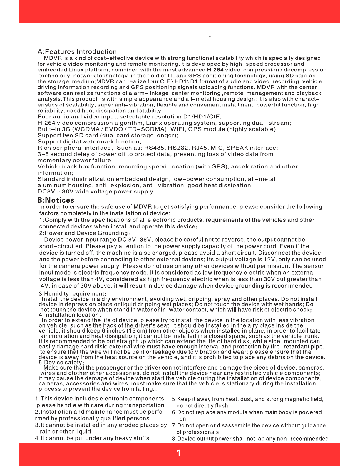
Section 1: Product Specifications
Note
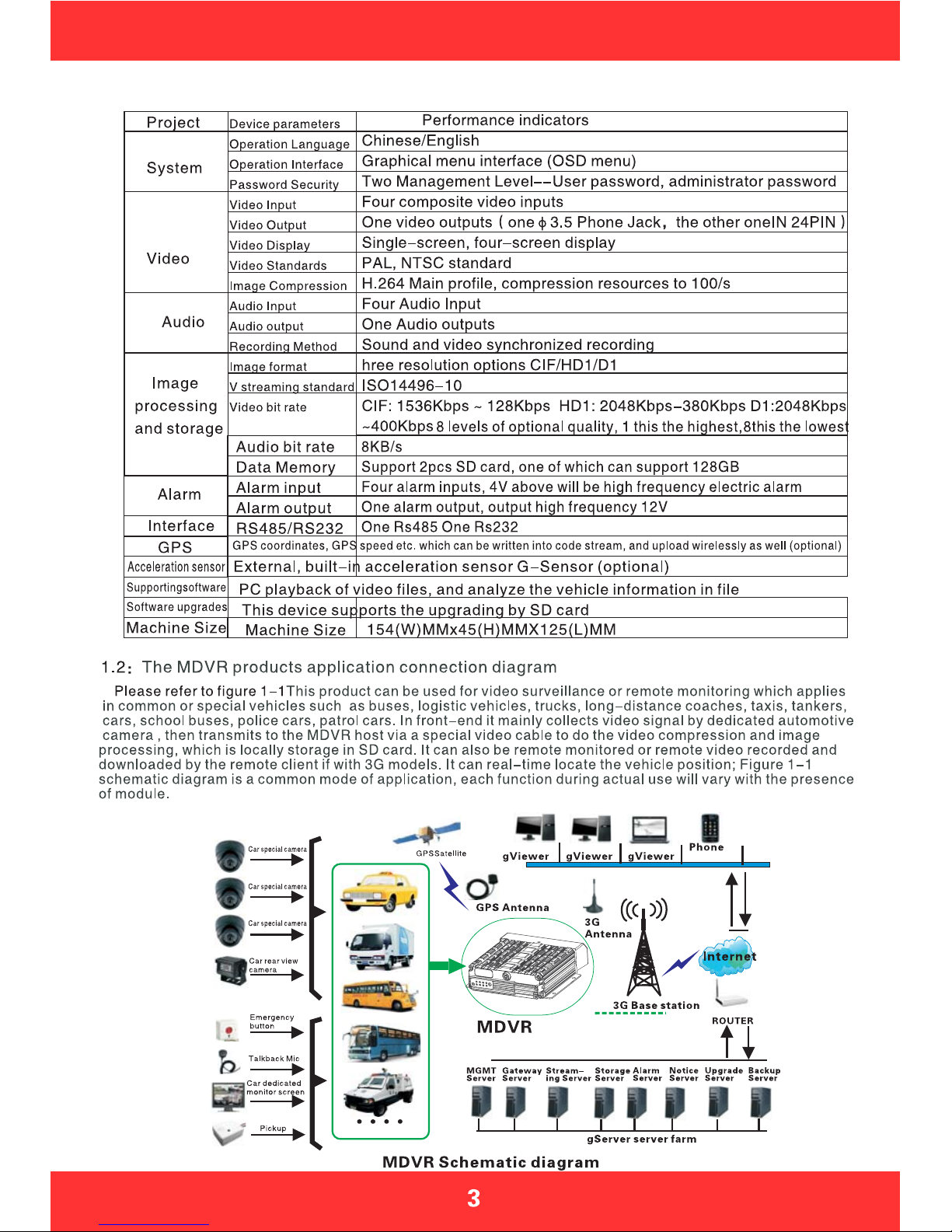
Table 2: MDVR Product Specifications II (Economic type)
gViewer
Pigure1-1

Section 2: Interface Definition and Functions
POWER CAM1CAM2CAM3CAM4
RJ45 MCU
GPS
3G
I/O&RS485&RS232
AV-OUT
BACK

Open the key,Left push
the SD card cover
Figure 2-6 Indicators Illustration
Panel Lights Instruction
AV-OUT Audio and Vedio output
SD1/SD2: Video SD card indicator
light on when the SD card exists
REC: Light on when recording
GPS: Light on when GPS module exists
POWER: Light on when power supply on
ALM: Light on when the machine in abnormal
CAM: Light on when video input 1/2/3/4
has signals; otherwise light off
3G: Light on when 3G communication
module exists
IR: Infrared receiver receives the remote
signal
Installed SD card and SIM card
Example Figure 2-3/4/5: Firstly host keys
must turn to the UN-LOCK position, then push
to open the SD card protection cover, insert
SD card into slot by SD card face up, then close
the protective cover; LOCK: It is necessary to
shut down the electronic lock before normal
starting up,the electronic lock of host is shut
down only when key position twists from UN-
LOCK to another position, and the host will start
up when power on;If twist the electronic lock to
UN-LOCK position when device is under normal
working status, the system will uninstall the SD
card and then extend 3-8 seconds to shut down.
IMcard:ThehostcanbeinsertedbyoneSIM
card under normal circumstances, two cards can
be inserted when customized, SIM card insert
way:metalsideup,notchforward.
SD
SD2
SD1
SIM A SIM B
SIM SIM
UN-LOCK
SD
SD2
SD1
SIM A SIM B
SIM SIM
UN-LOCK
Key switch
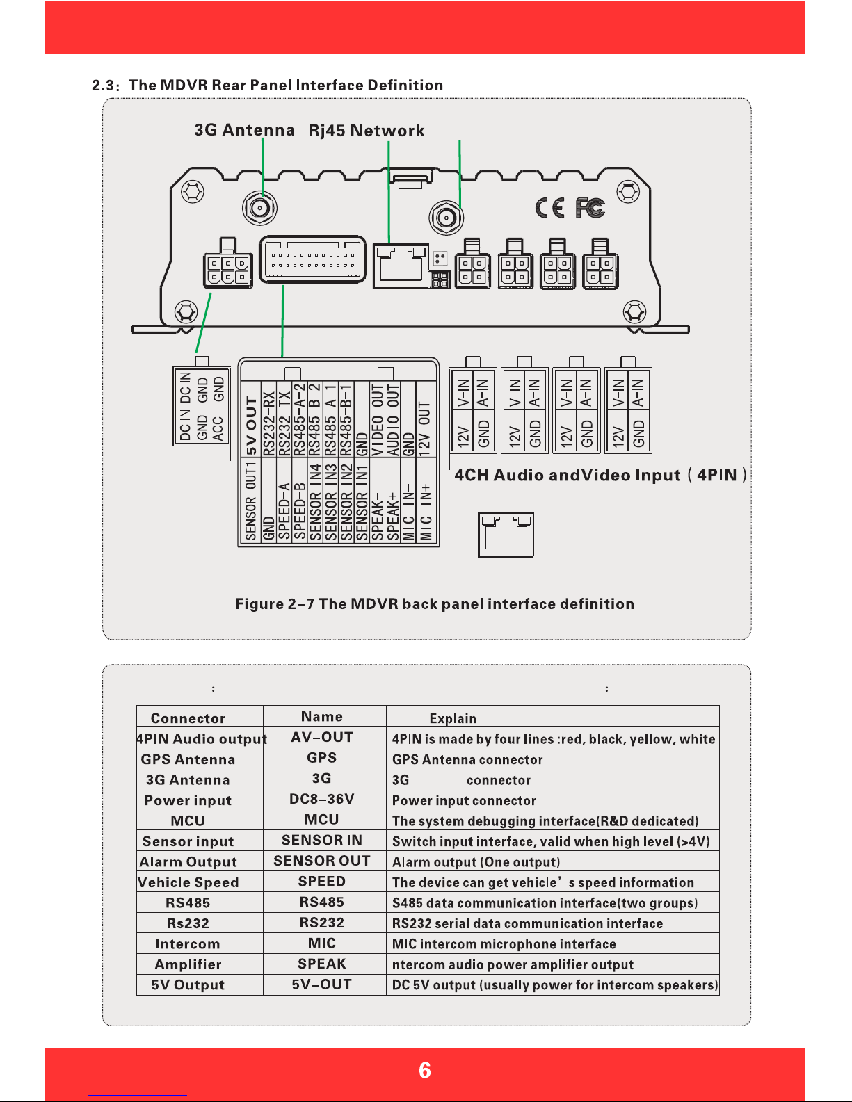
Table 3 The MDVR rear panel interface description as follows
Antenna
POWER CAM1CAM2CAM3CAM4
RJ45 MCU
GPS
3G
I/O&RS485&RS232
AV-OUT
POWER CAM2CAM3CAM4 CAM1
I/O&RS485&RS232
AV-OUT
Power Input
Red yellow black
GPSAntenna
RJ45
Connect to the
network interface
Front
PushtheSDcardcover
Right
Back
Right pushRight push
SD
UN-LOCK

POWER I/O MCU AV-OUT CAM1CAM2CAM3CAM4
POWER I/O
GPS
CAM2CAM3CAM4 CAM1
Table 4 (2)
The MDVR rear panel interface description as follows
GPS Antenna
Figure 2-10 MDVR panel interface definition (2)
Power Input
Red yellow black
4CH Audio andVideo Input 4PIN
2.6 Simple Instruction for Common Interface Wire
A:Power Cord
As shown by below pictures, one end is a 6PIN white plug, which will be connected to the 6PIN power
input connector on the rear panel of the device, the red and black wires are connected directly to the
vehicle battery or the gathered electric which go through battery and fuse; red wire links to positive while
the black line links to negative, the yellow wire links to firing wire, the main device automatically start up
when the vehicle s key is turned on, and shut off automatically after a delay when vehicle s key is
turned off; yellow wire links to the position when vehicle s key turn on all dashboard lights (the position
before vehicle starts the motor).
Power Line
Alarm I/O
1:Need to make sure the battery voltage is between 8V-36V before connecting, otherwise above voltage
will burn out the device
2:Pay attention to the insulation among the power cord after connection to prevent the short circuit of the
power cord which will burn out the battery and other electrical equipment in the vehicle
3:It is recommended to link the yellow wire to the firing wire, otherwise the device will not support the
delayed shutdown;
4:The installation of vehicle-mounted is recommended to directly take from battery positive and negative,
or pick from the main electrical with fuse, do not use ground because ground will produce negative pulses
which will interfere with the normal operation of the host. The diameter of positive and negative power
cord must be more than 1.5mm;
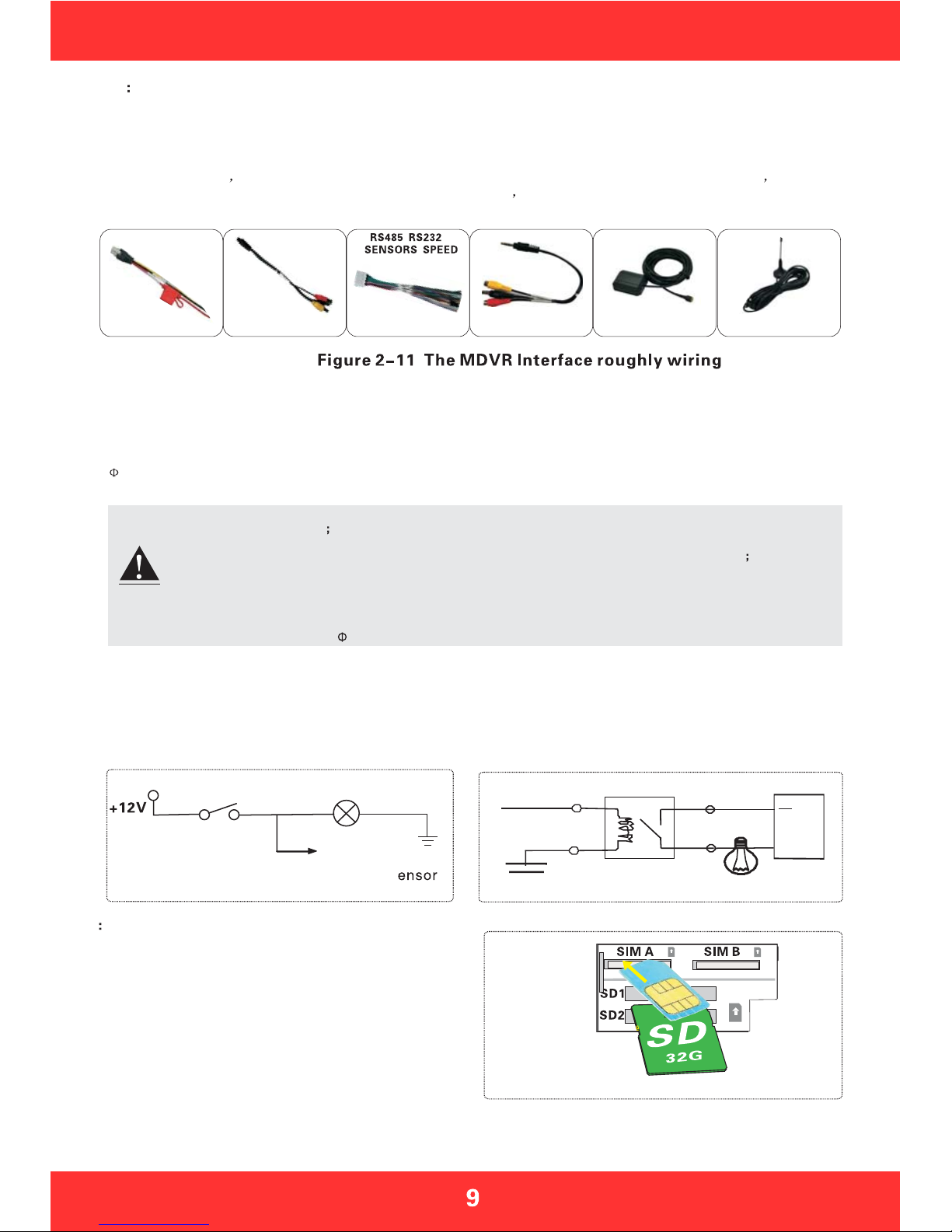
Above are the general ways of MDVR rear plate interface wiring, 4PIN testing wire is only used in the test which
is not recommended to be used in installation, it is recommended to use 4PIN audio and video extension cord during
installation; MDVR need dedicated 4PIN output wires when it is connected to the audio and video output, while the
3.5 Phone Jack interface in the front panel can also output audio and video. Its peripheral interface can be optional
3G/GPS, which then will need to use 3G antenna and GPS antenna, as shown in Figure 2-11
4PIN Test Line
B:Audio & Video wires
3G Antenna
GPS Antenna
C:Alarm input & output
This device has 4 alarm input and one alarm output interface, alarm input detection are all level detection which can
be accessed by a variety of vehicles driving state, such as brakes, steering, keyless entry, an emergency alarm
button etc. Brake, as shown in Figure 2-12, when the brake pedal is depressed, MDVR will be able to detect high
level, otherwise low level is detected. Alarm output are all level output with drive capacity of 200mA, if you want to
access the devices with larger power ratio, it is necessary to use external relay; alarm output photoelectric alarm
wiring diagram in Figure 2-13 as below.
+24V
MDVR Alarm output
MDVR Sensor
Input line S
Brake lights
Brake plate
Figure 2-12 Figure 2-13
If the MDVR supports 3G wireless communication
module, you will need to install SIM card which is
suitable for WCDMA / EVDO / TD-CDMA . SIM card
is in the front motherboard of the host, when the host
keyswiftstoUN-LOCK,opentheSDcardprotective
covertolefttoexposetheSDcardslotandSIMcard
slot, Metal SIM card face up, and the gap aligned
forward, mouth pressed into place, please remember
to pay attention to the positive and negative as well as
direction when inserting SIM card, after installation,
cover protective cover, then lock keys.
2.7 SIM Card Installation
4PIN-AV output line
Figure 2-14
Note

LOGIN
System intormation
Number key area
Exit/Return
Subtraction adjustment
PTZ control
Direction key area
Play back operation key area
4Images segmentation
PTZ Control Key area
Shortcut key/test key
Delete/Cancel
2.8 Remote Control Function keys Description
When VCR has a password, press the LOGIN button to enter the password, Since the
system does not have restoring or resetting function, please remember the password
Information Review
They are used to switch between the four-screen and single screen on the monitor
screen; press screen-split key to display 4 screens, press the number 1/2/3/4 to
correspondingly display channel1-channel 2 -channel3-channel 4
Return to the upper layer of the sub-menu. Eventually exit the setup menu and
return to the monitor screen
Pause key when play back image & data and single-step play key as well, each
press can play one step, press arrow keys to resume normal playback speed
Fast forward key when play back video data , fourth gear: 2X, 4X, 8X, 16X
Rewindkeywhenplaybackvideodata,fourthgear:2X,4X,8X,16X
Turn to next page/next one of searched files
Turn to previous page/previous one of searched files
LOGIN
INFO
FOUR SCREEN-
SPLIT NUMERIC
KEYPAD
RETURN
PAUSE/STEP
PLAY
FORWARD
REW
NEXT
PREV
Table 5 Remote Function Description
Automatic, preset, recall, zoom +, zoom - focus +, focus - aperture +,
aperture -, PTZ PRESET, RECALL, BRUSH
PTZ FUNCTION
KEYS
F1 F2 F3
F1 F2 F3 is the function testing key
Enter
Button of starting play(press this key to play when you have searched and selected the video file)

Section 3: Common quick setting and operation
The host s power cords are red, black and yellow, red and black wires connect directly to the vehicle battery
or go through vehicle fuse, the red wire links to the positive, while black wire links to the negative, yellow wire links
to firing wire ACC (the position before vehicle to start the motor). However, if under other testing environment
without vehicle, following wiring method is needed: twist red and yellow wires to link to the positive, black wire links
alone to the negative, then you can use the switch power supply above DC12V-5A to supply power to the host.
1:When power is supplied after correct wiring, the PWR blue light on the panel will keep on, standby
2:Connect the output wire AV-OUT to display and connect other according devices to the host, make sure the
connection is correct.
3:Need to turn off electronic lock with a key to the LOCK position (required) is the normal starting up,
the corresponding light turns yellow after starting up.
Below Figure 4-1 is testing wiring, as well as the the power supply wiring during actual loading.
Only used as a test wiring
Car circuit
control
Red line
Black line
Yellow line
Car battery
-
1 ThepowersupplyvoltageinputrangeisDC8-36V,whenthereisonlyabluelighton,itis
a standby state which is not really starting up; more than one light will be on under normal
start up status.
2 The host can not be delayed shutdown when you use testing wires for the power supply of host.
Need to use input method when input text, such as the company name, license plate number, driver's name, line
number, and other text input needs when requires input method under other menu. Take inputting Yue B95886
for example after entered the input interface to illustrate the input steps
Step One: in the state of Chinese input, as shown in Figure 4-2, Character YUE(GuangDong) s Pinyin is YUE,
move the cursor to press ENTER key to input the first Chinese letter y, it will display the corresponding PinYin
combination 1-5, if there is no PinYin as YUE, please press the FWD key on the remote control to the next pages;
when it shows 1.you 2.yu 3.yuan 4.yue 5.yun on the next page, please press the number 4 on the remote control
which will show 1-5pcs of Chinese characters, if there is no YUE character, please use FWD button to turn the
pages; when it shows 1 read 2 key 3 Yue 4 Guangdong Yue, please press 4 to input the first Chinese character
YUE(GuangDong).
Step Two: Now you will need to input the letter B, move the cursor to pressENTER key to switch the input method
to the state of capital letters, as Figure 4-3, then move the cursor onto the letter B to press ENTER key to input it.
Step Three: Next you will need to enter numbers, press it again to switch to Chinese input state, you can not input
numbers under Chinese input state, then you need to move the cursor to the "in (middle)" word, press ENTER key
to turn to EN, and then enter numbers 95886.
After the completion of above steps, press the RETURN key to go back and save, other text input under other
menus will be more or less the same. Please press CANCEL to delete it when there is a typo during the input process.
Connection diagram
Note

B peed alarm setting system menu - alarm settings - speed setting
If the vehicle selects the GPS to get speed information which requires normal status of the GPS signal, then
we need to set a high threshold speed limits, such as 100km/hthatisthemaximumspeed limit, alarm is
opened when vehicle is started;, vehicle will output alarm when the vehicle speed exceeds 100KM / H
If you choose to obtain speed information from the vehicle, it must be connected to the speed pulse sensor,
which is used to calculate the speed ratio (coefficient = pulse/speed), the pulse sensor is connected to the two
wires SPEED-A and SPEED-B of our device, the speed ratio will be measured according to the set speed and
pulse during vehicle s moving, which is a little complicated to operate; simple wiring in Figure 3-5.
Pulse sensor
C The acceleration alarm recording system menu - alarm settings - acceleration
Impact acceleration can be understood to be for a three-dimensional XYZ coordinate axis which can denote
three groups of status---up and down, left and right, front and rear; the bouncing up and down, accelerate,
Emergent brake, rollover, sharp turns, etc. during the moving process of the vehicle can all be expressed in
XYZ. Threshold needs to be set by an associated value, it is firstly needed a calibration after the installation
onto the vehicle, the calibration means to clear parametersX/Y/Z,secondly measure the allowed range of
emergent brake & acceleration & bouncing up and down as well as the change value of a sharp turn of the
vehicle during the operation, thereby to determine which axis s value changes a lot. These run status will be
in real-time display and change. After setting the threshold, when the vehicle runs exceed above threshold,
the alarm will be uploaded if the "alarm" opens.
D Motion detection alarm recording System Menu - Alarm Settings - Motion Detection
Turn on the motion detection enabled switch, set the sensitivity level of high, medium and low based on the
need, general settings is medium, and the next step is mostly to set the sensing area of the motion detection,
motion detection area will use diagonal set, please refer to Figure 4-30. As long as you set the motion
detection area and set the video mode as alarm recording, the image move will trigger the video to generate
alarm recording files (Note: it can only take effect after setting and saving)
3.3 Video settings
2 Timer recording
Firstly modify to be timing video under the System menu - Video Settings - General Settings - Video
mode, save and return to the previous menu level to be video plan, and then set the time period of the
video; save it after setting finished.
3 Alarm recording
Firstly modify to be alarm recording under the System menu - Video Settings - General Settings - Video
mode, then set the alarm pre-record time (range 0 -60s) and alarm video delay (30-900s); alarm output
delay (5S-255S), which can be set according to the actual external alarm device.
Secondly it is needed to install the corresponding external alarm input device, such as the emergency
button set by sensor, power switch for open/close door, brakes lights and other sensors; the following are
the several main alarm settings of this device:
A:The sensor input alarm system, system menu - alarm settings - sensor settings
Set the menu (in Figure 4-21) with high or low trigger level, and then turn on the alarm; this menu is
corresponding with four external alarm input SENSOR IN (which can be for eight external alarm output),
it must be connected to the corresponding external sensing switch device, such as door-magnet power
supply, emergency button, turning signal switch, brake lights (Figure 2-12), etc; rough connections are
shown in Figure 3-4.
External level input
External
sensor switch
Connect the the host back panel alarm interface
1 Video Start Up
After the installation of a new SD card in the device, the formatting is recommended after normal
boot into the system, in order for system to have better compatible relationship with its format. After
the formatting, host will automatically start up the video when restart.
GPS
I/O&RS485&RS232
AV-OU T
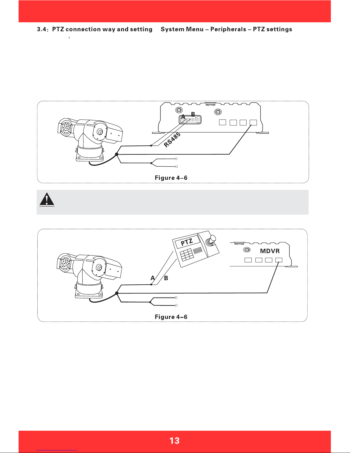
After wiring and parameters setting of PTZ, users can only use remote to control PTZ after
selecting the channel access to PTZ, for example, if PTZ connects through channel 2, then
you need to switch to channel 2 maximize on the monitor interface to control it.
Setup steps
Firstly, select the PTZ protocol: divided into PELCO-D and PELCO-P protocol, most of peoplewill choose
PELCO-D
Secondly, set the baud rate: there are four options 1200/2400/4800/9600 which must be corresponded with
thebaudrateonPTZ
Thirdly, set the address code: directly input the address value corresponding with PTZ setting, corresponding
is required. Generally the defaulted PTZ address code is 1, PTZ address code has adjustable DIP, it is needed
to set different address codes to identify when there is many PTZs.
Fourthly, wiring: Connect control wire 485 on the PTZ to the RS485-A positive pole, connect the other one
to the RS485-B negative pole.
The power input of the PTZ
Video
First way: the remote control PTZ wiring
Second way: with a three-dimensional
keyboard control PTZ
The power input of the PTZ
Video line
RS485
Connection Key
3D Key
Fifthly, there are three ways of wiring, the first way is connecting the 485 control wire to the wire 485A and
485B on host, connecting the video cable to the host video input and then provide power to PTZ; this kind
of wiring needs to set the MDVR host data be corresponding to PTZ data, and then use the remote controller
or platform to remotely control PTZ.
The second way, the head of the 485 control wire directly connect to the three-dimensional control keyboard,
do not need to connect the MDVR host, the video cable connects to the host video input, separately power
supply to the PTZ and three-dimensional keyboard, and then set the keyboard parameters to be corresponding
with PTZ. This wiring way is the most practical one, because it uses three-dimensional keyboard to control
PTZ, which is faster, easier and more practical. It is recommended to use this way to install PTZ
The third way is to connect to both car host and three-dimensional control keyboard, so that both can be
controlled and platform remote can also be controlled.
GPS
Note
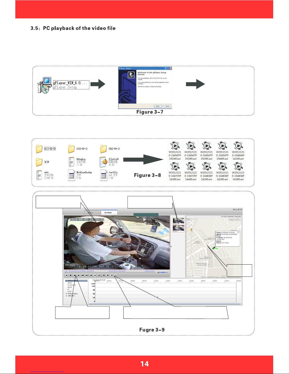
Besides playback by the host side, video files can also be copied to your computer to be played by the player.
Install the player
Double-click the installation file named MDVRPLayer V1.0.1.exe in the CD-ROM, and then select the
installation language (supporting Chinese and English), click OK and then keep clicking 'Next', a player
shortcut icon will show on the desktop after installation completion; installation steps shown in Figure 3-7
Playback
channel screen Play the file list
MAP
DSPLAY
STOP/PLAY/PAUSE
/FULL SCREEN
MULTI-SCREEN, CAPTURE,
AVI CONVERSION, SYSTEM SETTINGS
Remove the SD card from host and insert it into the card reader, then connect it to the computer's USB port,
the computer automatically recognizes the newly installed hardware; video files are stored in the form of
date folder, open the folder to display video file, video files are named with suffix ".264"
As shown by Figure 3-8, the screen show of playing the file in Figure 3-9
Step 1: Install the SIM card, 3G card which supports WCDMA / EVDO / TD-CDMA, detailed installation please refer
to Chapter II, 2.2, and 2.7
Step 2: Enter into the system menu after starting up, firstly modify the host s device number, System Menu -
General Settings - Vehicle Information - Device Number, device number range is from 00000 to 99999. Server
identifies the host according to the device number, so it is very important to modify the device number.
If the modified device number cannot be reported sometimes, please check the server device number has
been used or not.
Step 3: Modify the vehicle identification number; the vehicle information displayed on gServer platform is based on
vehicle identification number. If it is not modified, it will display 00000 in default. If all are in default, it would cause
inconvenience to find vehicles. So it is proposed to modify the vehicle identification number.
Step 4: Enter another menu settings, System Menu - General Settings - Network Settings, set the server IP and
control port, the server
can be self-built, and can be affiliated to the manufacturer s server as well, enter the server IP and control
port, which is typically 6608, the save by end.
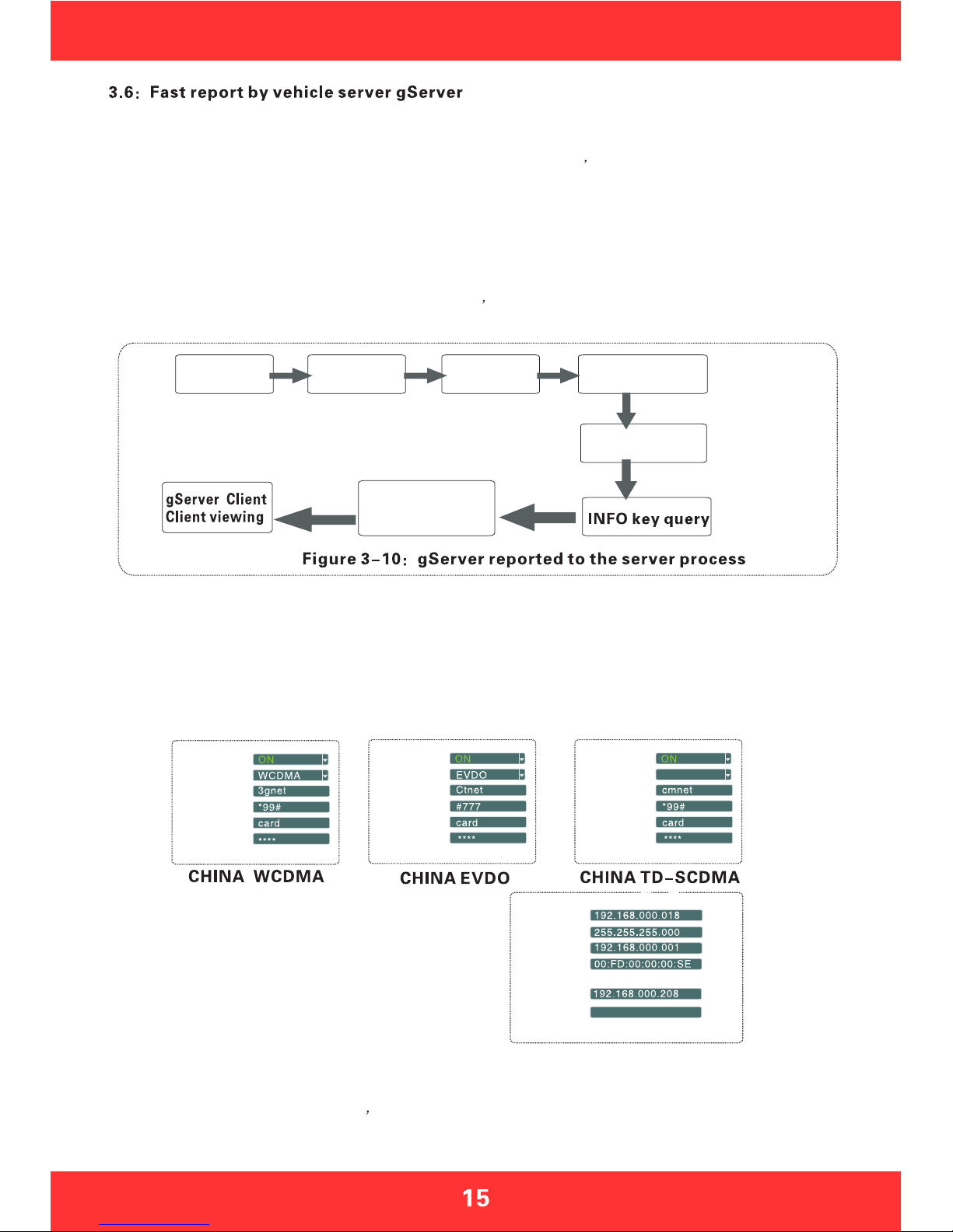
The main process of gServer quick reporting is as Figure 3-10 below.
Note: The following described iS invalid to the host which is without 3G module, it is not needed to report to gServer platform
Installing
the SIM card
Modify the
device NO
Modify the
license plate
number
Setup the server
address and port
3G settings
gServer manage
User name assigned
add vehicles
Step 5: Enter the system menu - peripheral - wireless broadband, which is with wireless settings inside.
A:wireless 3G settings
Please pay attention to the supporting type of network during wireless 3G setting: WCDMA, EVDO and
TD-SCDMA.Alsonotetheaccesspointandthecenternumber,Theusernameisindefaultindomestic
which is basically not needed to modify, however there is also in some domestic places he 3G card needs
tobeenteredbyusernameandpassword,andsomeforeignoperatorswillneedto enterusernameand
password as well, the access point and the center number will need to be modified too, which is required
to input relevant information according to the local network data. You can press INFO key to query whether
dialingissuccessfulornotaftersetting.
Step 6: Previous steps are the network connecting ways. When the network is connected, the next step is
the operation of software management on the PC gServer, which is divided into two steps. One step is the
gServer Manage username allocation and vehicle adding, if it is a self-built server, this work can be done
internally; if affiliated to manufacturer s server, this will need assist from the technical staff to add. The
other step is to log in gServer Client by user name to review, which ultimately achieves gServer reporting,
please refer to the CD-ROM gServer technical documentation for client's detailed operation
C:local IP settings
Local IP setting is the setting after the RJ45 port access
the network cable, set the local IP and central server
number to make it be linked from local area network to
WAN through the network cable, which can also report to
gServer server platform.
ENABLE
TYPE
APN
CENTER NUM
USER NAME
PASSWORD
IP ADDA
NERMASK
GATEWAY
MAC ADDA
SERVER IP
CONTROL PORT
6608
TD-SCDMA
ENABLE
TYPE
APN
CENTER NUM
USER NAME
PASSWORD
ENABLE
TYPE
APN
CENTER NUM
USER NAME
PASSWORD
Section 4: Menu function instructions
The system menu includes seven main menus: General settings, video settings, alarm settings,
system tools, peripherals, video search, system information; as shown in Figure 4-4
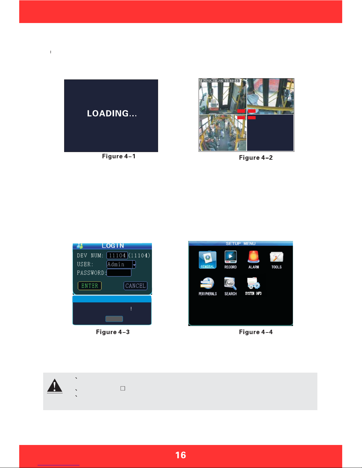
4.1 Device Start-up and User Login In
After host is installed in vehicle environment according to the installation instructions, start it up by
ensuring that power supply and other external devices are connected properly, normal start-up screen
as Figure 4-1. The machine starts to enter the normal quad monitor interface, as shown in Figure 4-2.
Description:
1.Device No.: user set the unique device number to each device, which will automatically display on the right
of the ID input box , it is required for unique device number for the same server, device number modifications
please refer to section 4.3-2
2.Username: Include administrator and operator, the Administrator has the authority to operate on all menus.
Operator has only view permissions.
3.Password: Enter the appropriate password according the selected username, select down key to move to
"OK"andpress"ENTER"tologinwhenthepasswordiscorrect;whenpasswordisincorrect,promptslogin
password error message, press OK to reenter the password. The initial password for administrator is 111111.
ThesystemmenuinterfaceafterloginisasshowninFigure4-4.
Press the LOGIN button on remote control to go directly into the login screen as shown in Figure 4-3
1 All of the following sub-menu settings must be confirmed to [save] to take effect,
otherwise the setting is invalid.
2 The check box filled means this function is selected, unfilled means it is not selected.
3 Numbers can be inputted directly by the number keys on the remote control or using the
soft keyboard. Letters input must be completed through the soft keyboard, Press
“RETURN" for submenu to go back.
REC REC
REC REC
00000 (00000)
CAUTION
password is error
ENTER
Note
Date,Time,Vehicle,User etc.
DATE&TIME
VEHICLE INFO
USER SETUP
NETWORK
NORAL
CODING SETUP
SUB-STREAM
RECORD PLAN
SENSOR
SPEED
G-SENSOR
TEMPERATURE
MOTION DETECTION
CONFIGURE
LOG
GENERAL
RECORD
ALARM
SYSTEM INFO
SEARCH
PERIPHERALS
LOGIN
TOOLS
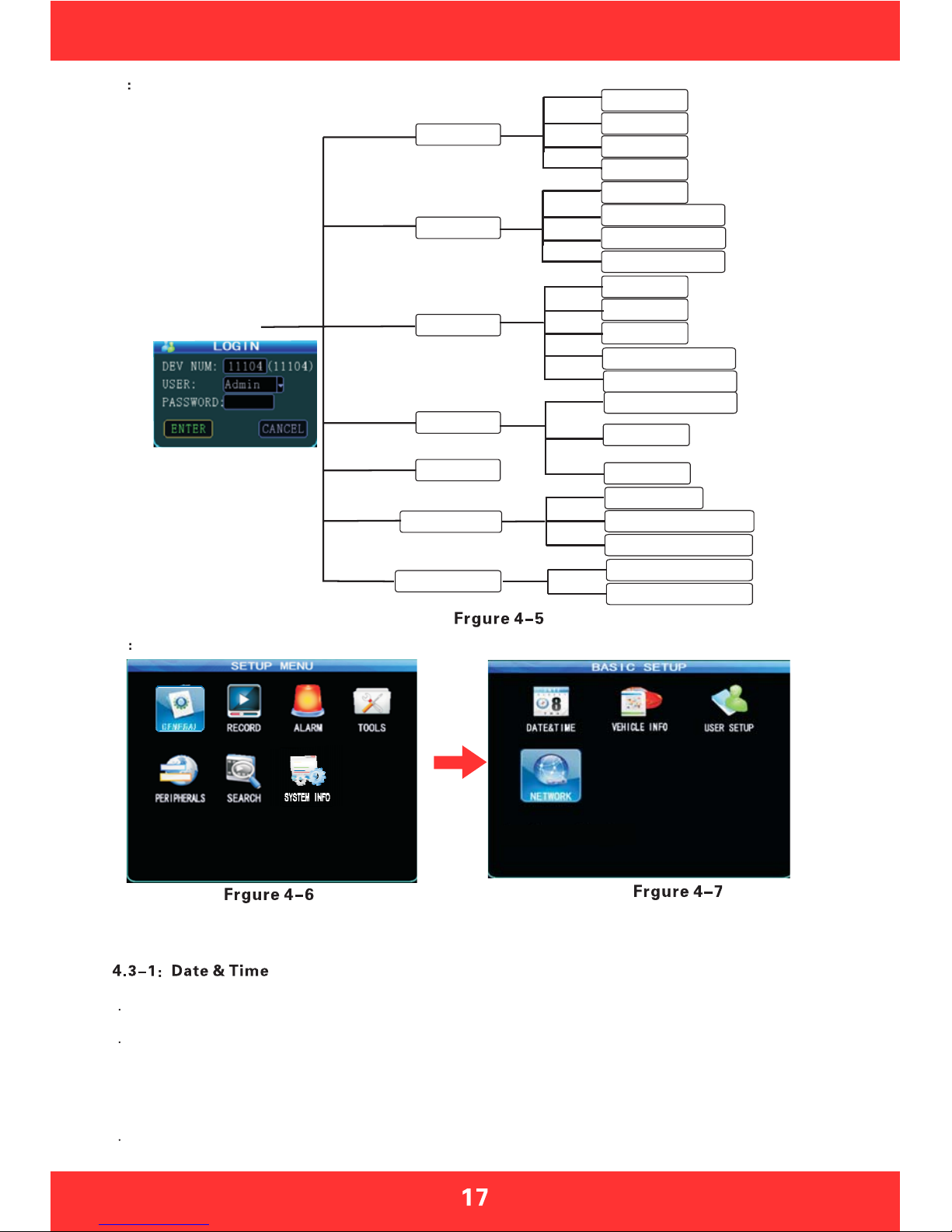
4.2 System Menu Organizational Framework
4.3G
eneral settings
General settings is the first menu in system menu, the generic setting interface contains four function
options: date and time, vehicle information, user management and network, as shown in Figure 4-7.
Set the system time and some other basic properties of the device, as shown in Figure 4-8
1 Date Format: Press "ENTER" drop-down menu to use the arrow keys to select the output format of date
(year-month-day, day-month-year, and month-day-year).
2 The date and time settings: two ways for time proofreading ---GPS time proofreading and manual time
proofreading, when select GPS time proofreading, the modified time will change because of reaching the GPS
time proofreading point, so if you want to modify the time, it is suggested to choose manual time proofreading
mode, which can be in normal after modifying time. Way of modifying the time and date: move the cursor to the
number which needs modification and directly press the corresponding number keys on the remote control,
press the save button after set.
3 Operating timeout: three options--1 minute, 5 minutes, 15 minutes for choosing to set how many minutes
later will automatically exit the menu after entering the menu. General settings menu interface
PTZ SETUP
WIRELESS SETUP
WIFI SETUP
SD/HDD STATUS
DEVICE STATUS
Default password:111111
FORMAT
System encoding,Recording time etc.
Date,Time,Vehicle,User etc.
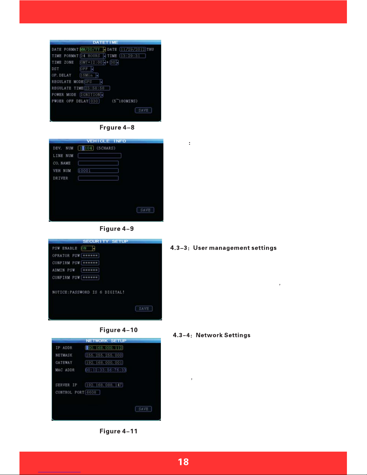
4.3-2 Vehicle settings
4:When the GPS time proofreading opens, in the default time
zone, such as the default GM +08:00 time zone, system will
automatically proofread time by GPS when it reaches time
proofreading point.
5:Switching machine: the ignition mode / timer mode, the
ignition mode is that MDVR began to start up after vehicle
starts its key, this operation is recommended as the preferred
default starting-up. timer mode is the operating mode of startup
and shutdown at the point of time set by the user.
6:Off delay: Either the ignition mode or timer mode, as long
as the wiring is correct, you can set the delay off of host,
delay off time range is from 5 minutes to 180 minutes, MDVR
will continue to do the video recording by the delay off set
time before shutting down when the vehicle is turned off.
Network setup interface is shown in Figure 4-11
1.IP address Mask Gateway etc are LAN network setting after
plugging in the network cable, there is no need to input if you do
not use them.
2.Server s IP address is the one MDVR host using 3G to report to
gServer platform central server, which generally is the public fixed
IP, the IP address must be set up, or else 3G host cannot report to
platform; this requires our host can support 3G; this menu will no
need of setting if the host is without 3G module.
3.Control port: set to be the port number of the gateway server,
generally the default is set to "6608" port
assword setup interface is shown in Figure 4-10
1.Password effective settings to select on or off
2.Only administrators have permission to modify the passwords
of users and administrators. Ordinary user s password is initially
set as 000000, and the initial password for administrator is 111111.
When password change finishes and exit menu, it will need to use
new password to log in again, the login screen shown in Figure 4-3.
General settings menu interface
1:Device No.: user sets a unique device number to each device,
which will automatically display on the right of the number input
box. The device number is 5 digits & characters, digits are
effective. If it is 3G device, it is strongly suggested to set a unique
device number, because a server requires only one device number.
2:Vehicle identification number: this number is recommended
to be set during installation, because the vehicle identification
number will be superimposed onto the video during video
encoding to be strong video evidence. If you do not enter the
vehicle identification number, then it will show 00000 in
default. For detailed input method, please refer to Chapter 3.2
3:Line number, company name, the name of the driver can
fill out as demand
Table of contents
Other Bolide DVR manuals


