Bolide SVR9000D T4 User manual
1
4/8CH Picture showed

User Manual
1
CONTENT
Safety Instruction ............................................................................................................................................................... 4
Chapter 1: Features........................................................................................................................................................... 5
Chapter 2: Overview.......................................................................................................................................................... 6
2.1 Front Panel.............................................................................................................................................................. 6
2.1.1、SVR9000D/T4 DVR Front Panel ............................................................................................................. 6
2.1.2、SVR9000D/T8 DVR Front Panel ............................................................................................................. 7
2.1.3、SVR9000D/T16 DVR Front Panel ........................................................................................................... 8
2.2 Rear Panel............................................................................................................................................................... 9
2.2.1、SVR9000D/T4 DVR Back Panel.............................................................................................................. 9
2.2.2、SVR9000D/T8 DVR Back Panel.............................................................................................................. 9
2.2.3、SVR9000D/T16 DVR Back Panel.......................................................................................................... 10
2.3 4/8-CH Remote Controller ................................................................................................................................... 11
2.4 16-CH Remote Controller..................................................................................................................................... 12
Chapter 3 DVR INSTALLATION .................................................................................................................................... 14
3.1 HDD Installation................................................................................................................................................. 14
3.2 Camera and Monitor Connection........................................................................................................................ 14
3.3 Power Supply connection ................................................................................................................................... 14
Chapter 4: DVR Boot up ................................................................................................................................................. 15
4.1 System Initialization ............................................................................................................................................. 15
4.2 Live Interface........................................................................................................................................................ 15
Chapter 5: DVR Menu........................................................................................................................................................ 15
5.1 Pop-up Menu ........................................................................................................................................................ 15
5.2 Main Menu Guide................................................................................................................................................. 16
5.3 Main Menu ........................................................................................................................................................... 17
5.3.1 Display ..................................................................................................................................................... 17
5.3.1.1 Live mode ....................................................................................................................................... 17
5.3.1.2 Output mode ................................................................................................................................... 18
5.3.1.3 Privacy Zone................................................................................................................................... 18
5.3.2 Record set............................................................................................................................................... 19
5.3.2.1 Record parameters .......................................................................................................................... 19
5.3.2.2 Schedule.......................................................................................................................................... 19
5.3.2.3 Main Stream.................................................................................................................................... 19
5.3.3 Search...................................................................................................................................................... 20
5.3.3.1 Record Search................................................................................................................................. 20
5.3.3.2 Channel Select ................................................................................................................................ 20
5.3.3.3 Event Search ................................................................................................................................... 20
5.3.3.4 File Backup..................................................................................................................................... 21
5.3.3.4.1 back-up file based on event ........................................................................................... 21
5.3.3.4.2 back-up file based on time ............................................................................................. 21
5.3.3.4.3 Media Player backup ...................................................................................................... 22
5.3.3.5 Log Search...................................................................................................................................... 23
5.3.4 Network.................................................................................................................................................... 23
5.3.4.1 Network set..................................................................................................................................... 23
5.3.4.2 Router’s Port Forwarding ............................................................................................................... 24

User Manual
2
5.3.4.3 Sub stream ...................................................................................................................................... 25
5.3.4.4 Email set ......................................................................................................................................... 25
5.3.4.5 Mobile Set....................................................................................................................................... 25
5.3.4.6 DDNS Set ....................................................................................................................................... 26
5.3.5 Alarm ........................................................................................................................................................ 26
5.3.5.1 Motion............................................................................................................................................. 26
5.3.5.2 Alarm Set ........................................................................................................................................ 27
5.3.6 Device ...................................................................................................................................................... 28
5.3.6.1 HDD Set.......................................................................................................................................... 28
5.3.6.2 PTZ Set ........................................................................................................................................... 28
5.3.7 System..................................................................................................................................................... 29
5.3.7.1 General............................................................................................................................................ 29
5.3.7.2 DST Set........................................................................................................................................... 29
5.3.7.3 Network Time Protocol (NTP) Service........................................................................................... 29
5.3.7.4 Users ............................................................................................................................................... 29
5.3.7.5 Information ..................................................................................................................................... 30
5.3.8 Advanced................................................................................................................................................. 31
5.3.8.1 Maintain.......................................................................................................................................... 31
5.3.8.2 Event ............................................................................................................................................... 31
5.4 Menu Lock............................................................................................................................................................ 31
5.5 Split mode............................................................................................................................................................. 32
5.6 PTZ Control.......................................................................................................................................................... 32
5.7 PIP Mode .............................................................................................................................................................. 33
5.8 Record search ....................................................................................................................................................... 33
5.9 Mute...................................................................................................................................................................... 33
5.10 Manual Record.................................................................................................................................................... 33
5.11 Stop record.......................................................................................................................................................... 33
5.12 Start Sequence .................................................................................................................................................... 33
5.13 Start Cruise ......................................................................................................................................................... 33
Chapter 6:Web Application Manager ............................................................................................................................ 34
6.1 Plug-in download and installation ........................................................................................................................ 34
6.2 WebApplication Manager Log-in ......................................................................................................................... 37
6.3 Live interface........................................................................................................................................................ 37
6.3.1 Menu Bar................................................................................................................................................. 37
6.3.1.1 Live Display.................................................................................................................................... 37
6.3.1.2 PTZ Control.................................................................................................................................... 38
6.3.1.3Video control ................................................................................................................................... 38
6.3.2 Playback .................................................................................................................................................. 38
6.3.2.1Record search................................................................................................................................... 39
6.3.2.2 Playback control ............................................................................................................................. 40
6.3.3 Configuration........................................................................................................................................... 41
6.3.3.1 Display Configuration..................................................................................................................... 41
6.3.3.2 Record............................................................................................................................................. 42
6.3.3.3 Network Parameters........................................................................................................................ 42
6.3.3.4 Alarm Set ........................................................................................................................................ 45
6.3.3.5 Device ............................................................................................................................................. 46

User Manual
3
6.3.3.6 System............................................................................................................................................. 46
6.3.3.7 Advanced ........................................................................................................................................ 47
6.3.4 Local setting............................................................................................................................................ 49
6.3.5 Logout ...................................................................................................................................................... 49
Chapter 7: Specification.................................................................................................................................................. 50
Chapter 8:Appendix......................................................................................................................................................... 53
8.1 Record Alarm setting ............................................................................................................................................ 53
8.2 Mail box server List.............................................................................................................................................. 53
8.3 Troubleshooting .................................................................................................................................................... 54
8.4 Usage Maintenance............................................................................................................................................... 54
8.5 System Connection Diagram ................................................................................................................................ 55
8.6 Accessories ........................................................................................................................................................... 56

User Manual
4
Safety Instruction
1. Read Instruction
All the safety and operating instruction should be read before the equipment is operated.
2. Power sources
This equipment should be operated only from the type of power source indicated on the marking label. If
you are not sure of the type of power, please consult your equipment dealer.
3. Objects and Liquid
Never push objects of any kind through openings of this equipment and / or spill liquid of any kind on the
equipment as they may touch dangerous voltage points or short out parts that could result in a fire or electric
shock.
4. Water and / or Moisture
Do not use this equipment near water or in contact with water.
5. Heat sources
Do not install near any heat sources such as radiators, heat registers, stoves or other apparatus (including
amplifier) that produce heat.
6. Dusty field
Never use this equipment near dusty or intense magnetic field.
7. Cleaning
Unplug this equipment from the wall outlet before cleaning it. Do not use liquid aerosol cleaners. Use a
damp soft cloth for cleaning.
8. Lightning
Unplug this equipment during lightning storm or when unused for long periods of time.
9. Accessories
Do not place this equipment on an unstable cart, stand or table. When a cart is used, use caution when
moving the cart / apparatus combination to avoid injury from tip-over.
10.Moving
Disconnect the power before moving the equipment. And the equipment should be moved with care.
11. Attachment
Never add any attachments and/or equipment without the approval of the manufacturer as such additions
may result in the risk of fire, electric shock and other personal injury.
12. Correct Batteries
Risk of explosion occurs if battery is replaced by an incorrect type. Therefore you must use the same type
of battery as the one being used in the product.
13. Ventilation.
Do not block any ventilation openings, installation of the equipment in the rack should be such that the
amount of airflow required for safe operation of the equipment is not compromised.
14. Overloading
Do not overload wall outlets and extension cords to avoid the risk of fire or electric shock.
15. Reliable Earthlings (Grounding)
Reliable grounding of rack mounted equipment should be maintained. Particular attention should be given to supply
connections other than direct connections to the branch circuit.

User Manual
5
Chapter 1: Features
Function Brief and Description
Real time
monitoring
Double video output; with monitor, VGA virtual output port or HDMI Output;
Support net-viewer and MP live surveillance and also support zoom in/out,
auto sequence and PIP display.
Record
H.264 video compression format; record quality/resolution/frame rate
adjustable, multiple record modes (Always, Scheduled, Manual, Alarm,
Motion detection and remote record)
Record
storage Support SATA large capacity HDD and save real-time record image to HDD.
Playback Support DVR single CH and multiple CH Search/Playback of recorded files.
Backup Support DVR backup via USB flash drive, removable drive, Recorder and
network.
Alarm Setting Supports HDD & video input alarm management and external alarm signal
inputs.
Network
operation
Supports remote surveillance by authority users to increase system
security.
Mouse
Operation Supports Mouse operation for faster menu navigation.
PTZ Control Supports PTZ camera operations through RS-485.
List 1-1
Features:
H. 264 video compression format; supports D1 resolution(16CH DVR not supported D1);
ADPCM audio compression format
Windows Graphical interface; embedded real-time Linux2.6 operation system;
Friendly Menu reminder;
Multiple operation modes (Preview, record, playback, backup, network surveillance and mobile phone
monitoring);
Supports Double Encode bit network transmission;
Supports remote live surveillance via 3G mobile networks;
Supports Zoom in/out and sequence function;
The video package time is adjustable;
Multiple alarm record modes;
Rear USB2.0 ports for back-up, upgrade and mouse operation;
With IR remote control operation;
Multiple language OSD;
Support auto-maintain.
User Manual
6
Chapter 2: Overview
2.1 Front Panel
Reminder: DVR is the abbreviation of Digital Video Recorder Equipment.
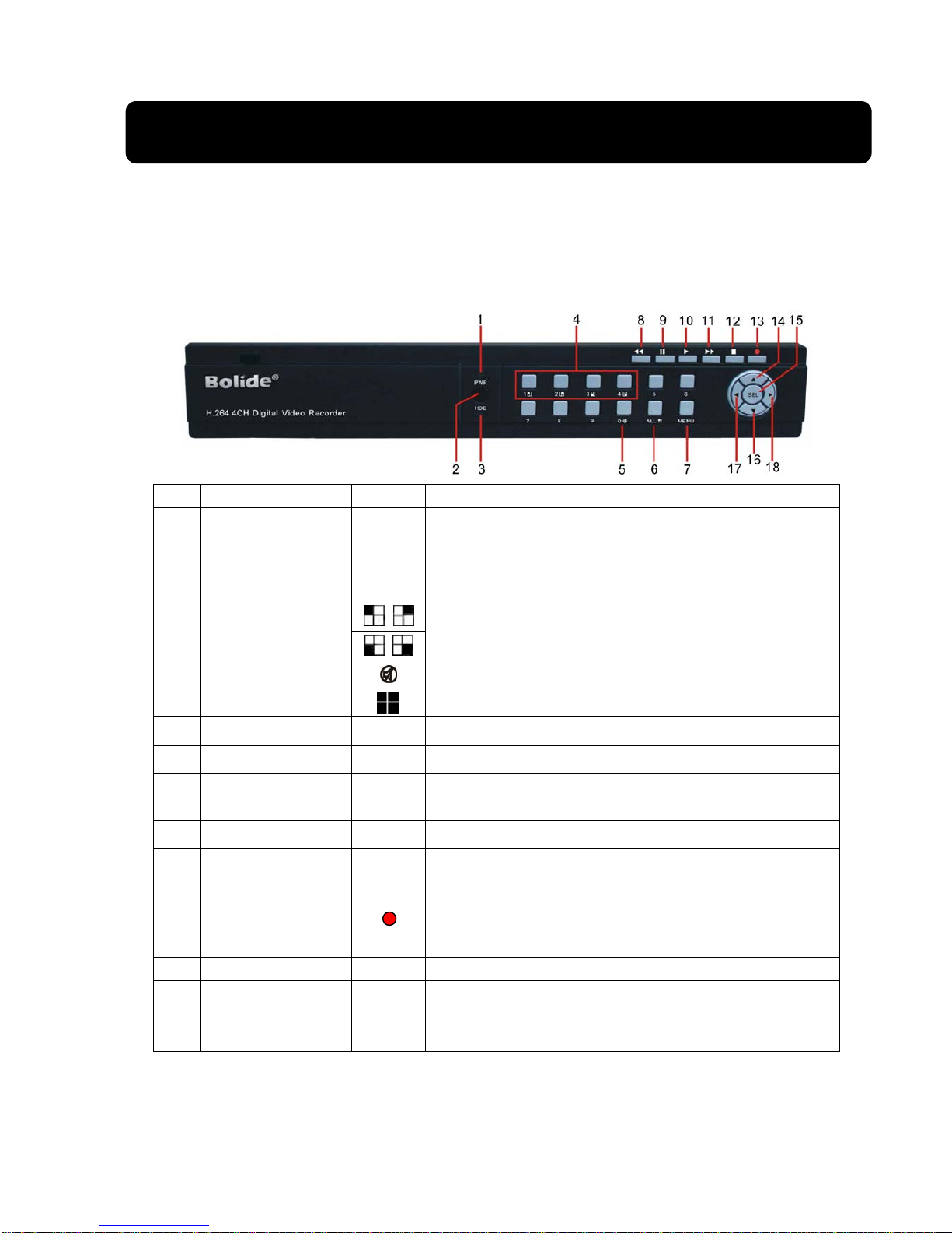
2.1.1、SVR9000D/T4 DVR Front Panel
Item Key title/Indicator Marks Functions
1 Power indicator PWR If the “Green” indicator is on, the system is getting power
2 IR Receiver Receives signal from Remote Control
3 HDD indicator HDD When the “Red” indicator flashes, it means the hard drive is
being read or written to.
4 Channel Select:
CH1 CH2 CH3 CH4
Select Single Channel Display
5 Disable or Enable audio preview
6 ALL Display all cameras in Live display or playback mode
7 MENU Enter into main menu or exit menu
8 REW Move Left / Rewind
9 PAUSE Pause / play frame by frame, dwell time (sequential channel
switch) during single camera display
10 PLAY Enter into pop-up Menu/Play
11 FWD Move Right / Play Forward
12 STOP Stop Playback; stop manual recording
13 REC Start Manual recording
14 Up Move Up
15 SEL Enter into pop up menu; Select key / Edit
16 Down Move Down
17 Left Left Arrow
18 Right Right Arrow
List 2-1
User Manual
7
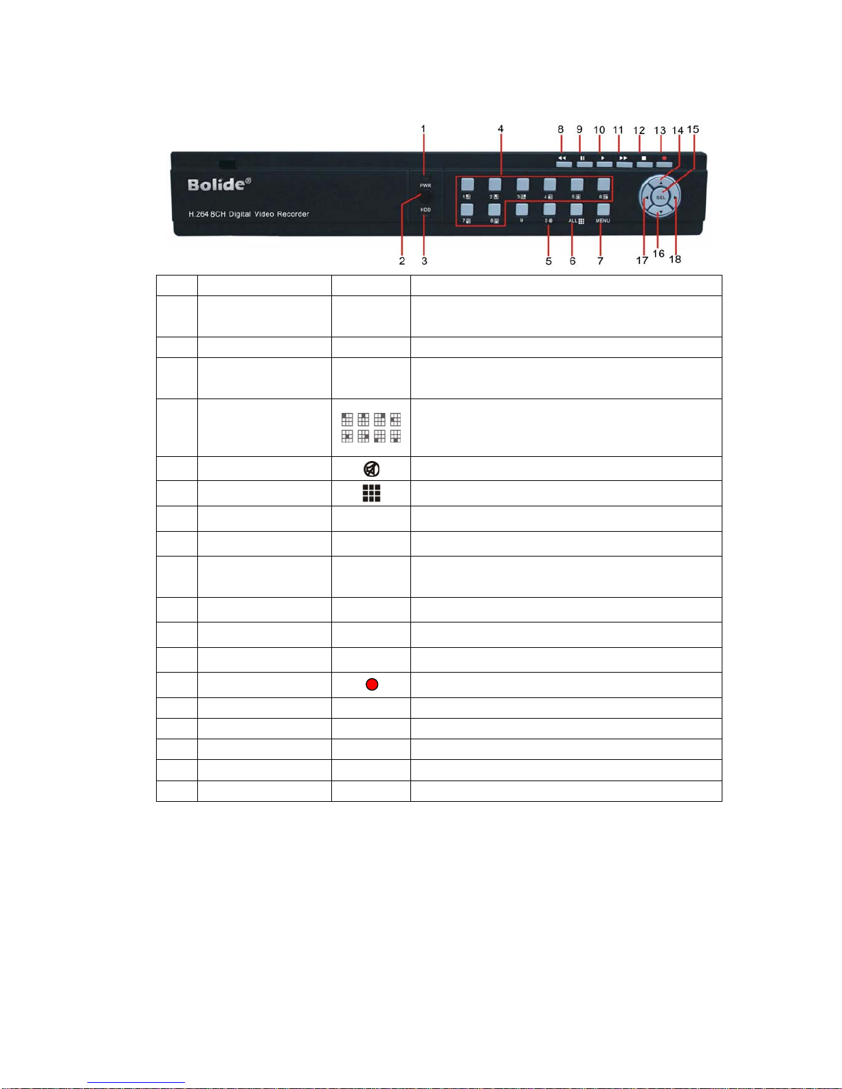
2.1.2、SVR9000D/T8 DVR Front Panel
Item Key title/Indicator Marks Functions
1 Power indicator PWR If the “Green” indicator is on, the system is getting
power
2 IR Receiver Receives signal from Remote Control
3 HDD indicator HDD When the “Red” indicator flashes, it means the hard
drive is being read or written to.
4 Channel Select:CH1-
CH8 Select Single Channel Display
5 Disable or Enable audio preview
6 ALL Display all cameras in Live display or playback mode
7 MENU Enter into main menu or exit menu
8 REW Move Left / Rewind
9 PAUSE Pause / play frame by frame,dwell time (sequential
channel switch)during single camera display
10 PLAY Enter into pop-up Menu/Play
11 FWD Move Right / Play Forward
12 STOP Stop Playback; stop manual recording
13 REC Start Manual recording
14 Up Move Up
15 SEL Enter into pop up menu; Select key / Edit
16 Down Move Down
17 Left Left Arrow
18 Right Right Arrow
List 2-2
User Manual
8
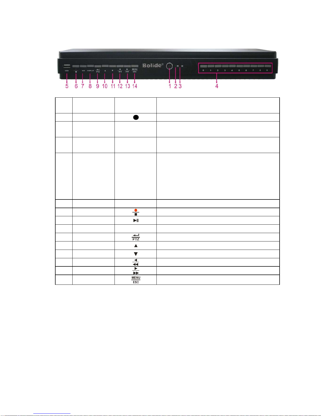
2.1.3、SVR9000D/T16 DVR Front Panel
Item Key title
/Indicator Marks Function
1
Receives IR signal from Remote Control
2 Power indicator PWR If the “Green” indicator is on the system is getting power
normally.
3 HDD indicator HDD When the “Red” indicator flashes it means the hard drive is being
read or written to.
4 Single Channel and
numeric key
Numeric key 0,1-9
and CH key CH1~9
1. Number 1~9 stand for numeric 1~9 and CH 1~9.
2. CH11-CH16 select method: press firstly numeric key 1 and
then other numeric key. For example CH16 select firstly
press 1, and then press 6.
Holding press key 0 for three seconds may convert current output
device
5 USB Port Connect to USB2.0 port
6 Manual record/Stop Manual record/Stop
7 Play /Pause Press the button to start or Stop playing
8 DISPLAY Live Quad display, 9-split display and 16-split display
9 PTZ Enter into PTZ control, select [Enter] / [Edit] operation
10 UP Move up
11 DOWN Move down
12 LEFT Move left / RWD
13 RIGHT Move right / FWD
14 Menu Enter into main menu / Exit
List 2-3
User Manual
9
2.2 Rear Panel
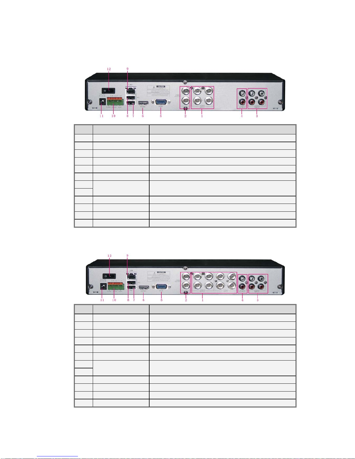
2.2.1、SVR9000D/T4 DVR Back Panel
Item Physical port Connection method
1 Video input Connect CH1-4 (Virtual) video input device(BNC interface)
2 Video output Connect monitor output(BNC interface)
3 Audio Input 4CH audio input (BNC interface)
4 Audio Output 2CH output; RCA(interface)
5 VGA Port Connect to VGA monitor, such as PC monitor (Optional)
6 HDMI HDMI Output
7 USB Port Connect USB mouse\USB device (Flash Drive, Hard Drive and
Recorder etc
)
8
9 Ethernet: Port Connect LAN, Ethernet (RJ45 interface)
10 RS-485/Sensor/Alarm RS485/Sensor/Alarm interface (see pin outs below)
11 Power Port Connect power supply - DC12V 3A
12 Power Switch Turn Power on and off
2.2.2、SVR9000D/T8 DVR Back Panel
Item Physical port Connection method
1 Video input Connect CH1-8 (Virtual) video input device(BNC interface)
2 Video output Connect monitor output (BNC interface)
3 Audio Input 4CH audio input (BNC interface)
4 Audio Output 2CH output; RCA(interface)
5 VGA Port Connect to VGA monitor, such as PC monitor (Optional)
6 HDMI HDMI Output
7 USB Port Connect USB mouse\USB device (Flash Drive, Hard Drive and
Recorder etc
)
8
9 Ethernet: Port Connect LAN, Ethernet (RJ45 interface)
10 RS-485/Sensor/Alarm RS485/Sensor/Alarm interface (see pin outs below)
11 Power Port Connect power supply - DC12V 3A
12 Power Switch Turn Power on and off
User Manual
10
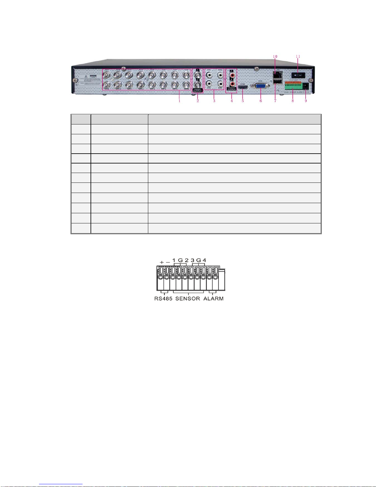
2.2.3、SVR9000D/T16 DVR Back Panel
Item Physical port Connection method
1 Video input Connect CH1-16 (Virtual) video input(BNC interface)
2 Video output Connect monitor output(BNC interface)
3 Audio input Connect CH1-4 audio signal input (BNC interface)
4 Audio output 2CH output; BNC (interface)
5 HDMI HDMI Output
6 VGA Port Connect to VGA monitor, such as PC monitor
7 USB Port Connect USB mouse
8 RS-485/Sensor/Alarm RS485/Sensor/Alarm interface (see pin outs below)
9 Power Port Connect power supply - DC12V 5A
10 Ethernet: Port Connect LAN, Ethernet (RJ45 interface)
11 Power Switch Turn Power on and off
RS485/Sensor/Alarm port functions:
Alarm input: Connect [-] port of your sensor to G (GND) pin, and [+] port to channel input according to the
alarm device you purchased.
Alarm output: Connect to the two ports marked with “out”
PTZ Port:Connect your camera to RS-485A and RS485B accordingly.
User Manual
11
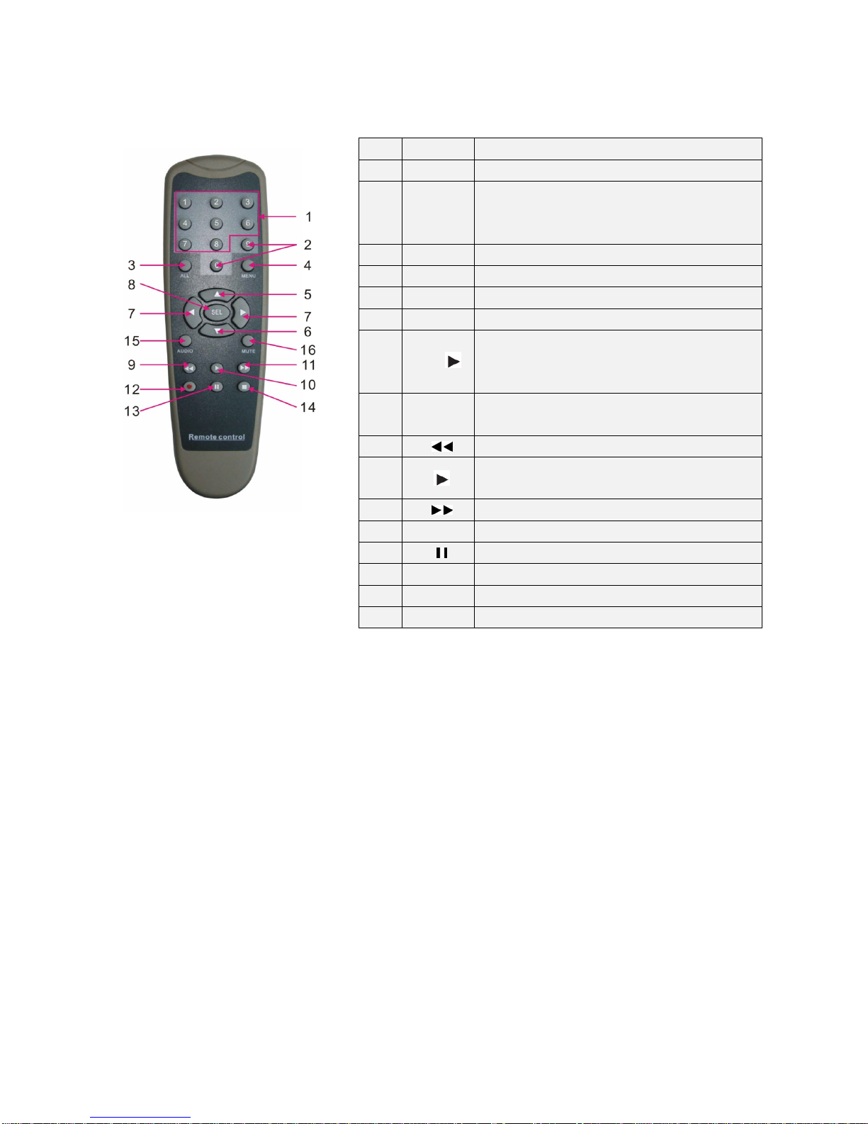
2.3 4/8-CH Remote Controller
Item Key title Key function
1 1-8 Channel select 1-8; Numeric key
2 9、0
Numeric key; Clicking numeric “0” allow you
switch to GUI (Graphical user Interface)
function
3 ALL Multiple display mode
4 Menu Enter into Main menu/Exit
5 ▲Up arrow key, Volume adjust
6 ▼Down arrow key, Volume adjust
7 ◄/
Left/Down key,
Decrease/increase parameter value of
control bar
8 SEL Select key/Edit key;
Confirm the selected operation.
9 Rewind key
10 Enter into record search menu;
Play key
11 Forward key
12 ●Record key
13 Pause/Sequence key
14 ■Stop manual record; stop playing
15 Audio Testing
16 Mute Mute on/off

User Manual
12
2.4 16-CH Remote Controller
Key Title Key Function
REC Press the button to enter into manual record.
SEARCH Press the button to enter into record search menu
2×2 Enter into Quad display
3×3 Enter into 9-split display
4×4 Enter into 16-split display
AUTO Enter into dwell time display
0~9 Channel select; numeric key
DISPLAY
MODE
Multiple CH display (Quad, 9-split, 16-split and full
screen display)
▲Up direction key
▼Down direction key
◄/
Left/right direction key; also decrease/increase
parameter value of control bar.
ENTER select [Enter] / [Edit] operation
Menu/ESC Enter into/exit Main menu
PIP PIP display mode
MUTE Mute key
FWD Forward(x2、x4、x8)
REW Rewind(x2、x4、x8)
PLAY Enter into record search, play record event
STOP Stop play / manual play
PAUSE/
FRAME Pause / play frame by frame
SLOW (1/2、1/4、1/8)Slow play
Z+ Zoom out video area
Z- Zoom in video area
F+ Extend focus
F- Extend focus
I+ Increase PTZ brightness
I- Decrease PTZ brightness
PTZ Allow you set preset bit and control PTZ.
LOCK Lock system

User Manual
13
Mouse Operation
Except using buttons of front panel or remote controller, you also can use mouse to perform system operation.
TYPE Function
Click left key of
Mouse
In menu lock mode, Enter into pop-up menu and clicking any sub menu to
pop up Log-in window; on menu unlock mode, enter into pop-up menu, and
then clicking left key to enter into any sub menu directly.
After entering into main menu, clicking left key could enter into any sub
menu; On [Detailed file] menu mode, clicking left key could playback one
recording file.
Change the status of check box and motion detection area.
Clicking combo box to access pull-down menu; Click left key to stop dwell
time display when dwell time display is activated.
By clicking left key you can adjust Color control bar and volume control
bar.
Clicking combo box to access pull-down menu
By clicking left key you can select values in edit boxes or pull-down menu
and supports Chinese word input, special symbol, numeric and character input,
use instead of [Enter- ] or [Backspace ]
Click right
key of Mouse
In live display mode, clicking right key will display pop-up menu (shown
as Picture 5-1).
In Main menu or sub menu mode, clicking right key will exit current menu.
Double-click Left
key of Mouse
In live display or playback mode, double-clicking left key will maximize
the screen.
Moving Mouse Select menu item
Sliding Mouse On motion mode, sliding mouse will select motion area; On [Color set]
menu mode, sliding mouse will adjust color control bar and volume control bar.

User Manual
14
Chapter 3 DVR INSTALLATION
3.1 HDD Installation
Caution:Please do not Install or take out hard drive when DVR is running!
(1) Cut power firstly, and then remove screws and open DVR upper cover carefully;
(2) Insert Power Cord and data cable into Pin of hard drive securely;
(3) Remove the screws on the HDD bracket; fix the HDD to the bracket and then fix the bracket with HDD
to DVR body
(4) Put the upper cover back carefully, re-attach screws.
Note: If user requires higher performance HDD, strongly recommend you use special hard driver for
security and protection
3.2 Camera and Monitor Connection
Connect camera cable to video input of DVR, and from video output of DVR to Monitor via BNC connector
(Refer to section2.2-Rear Panel); or
If the camera is a PTZ speed dome, you could connect RS485 A & B to the according port of DVR
respectively (refer to system figuration on Chapter 8).
3.3 Power Supply connection
Please only use the power adapter supplied with the DVR.
After power on please make sure the video I/O connection well, audio device with RCA cable.

User Manual
15
Chapter 4: DVR Boot up
4.1 System Initialization
Picture 4-1
4.2 Live Interface
Picture 4-2
area outside the menu allows you exit the Pop-up menu.
Note: When internal HDD is not connected or an error occurs, the character “H” will appear on the first channel
of the live screen and accompany buzzer alarm. If you want to close the buzzer alarm, please enter into [Main
menuAlarm] to set HDD loss, HDD space not enough and alarm output to “off”
Chapter 5: DVR Menu
5.1 Pop-up Menu
After finishing system initialization, click
right key of mouse on main interface mode to
enter into Pop-up Menu. Now you could perform
parameter setting and operate on Main Menu,
Multi-Pics, PTZ, PIP, Rec. Search, Mute,
Manual record, Start Rolling, Start Cruise and
Vo Switch etc.
Clicking [0] key on the remote controller or
holding press [Esc] key on the front panel could
switch system to other output device.
After finishing initialization the system will enter into <Live>
screen. Picture 4-2 is the 16-split display defaulted by system, which
is showing no video input status. Once there are video inputs, the
screen will display live images from the cameras. In Live mode, if
you use the mouse to double-click the live image of any channel, the
image will be maximized to full screen, by double-clicking again,
image will be come back to 16-split display mode; clicking the right
button of the mouse will enter into Pop-up Menu; clicking the left
button of the mouse allows you select menu items; and clicking any
After connecting the Power cable of DVR to wall outlet and
pressing the Power button on the front panel, you will enter into the
system initializing screen shown as Picture 4-1
Picture 5-1

User Manual
16
5.2 Main Menu Guide
MainMenu
Maintain
Advanced
Event
System Users
SystemInformation
General
Device PTZset
SerialSet
HDD
Motion
Alarmset
Alarm
Search
RecordSearch
Event Search
Backup
Log search
Display OutputSet
Liveset
PrivacyZone
Record
RecordParameters
Schedule
MainStream
Network
Substream
NetworkSet
EmailSet
MobileSet
DDNSSet

User Manual
17
5.3 Main Menu
5.3.1 Display
5.3.1.1 Live mode
Go to <Main menuDisplayLive> option and enter into the <Display> setting interface shown as Picture 5-3.
Channel: allow you setup the channel you desired.
Name: allow you setup the channel name, and system support up to eight characters or four Chinese
characters.
Position: allow you setup the display position of each channel.
Color: Click [Setup] option to enter into the [Color setup] interface shown as Picture 5-4.
Covert: allow you enable [Live] surveillance screen
Show time: allow you enable system time appear in the <Live> screen.
Record time: When set to “Enable”, you are allowed to record system time into the record history.
Copy: allow you copy all data of one channel to any other one
Above picture 5-4 is the Color Menu where you can adjust image brightness, saturation, contrast and hue
parameters of each channel.
Explanation:
1、The modifications will be available after clicking [APPLY] button on the bottom of the sub-menu windows
and being prompted to save and then clicking [ok] button.
2、If you want to cancel the modification, click [Exit] button to exit the menu.
3、When clicking [DEFAULT] button, all system default values will be reset to default value.
4、System default value indicates the value pre-set at the factory.
On <Live> mode, click [Menu] button on the front panel or
Remote controller to enter into Main menu interface shown as
Picture 5-2. And also you can click [ ] icon to enter the main
menu screen. In Main Menu mode, you can control device
management settings, such as Display, Record, Network,
Search, Device, System and Advanced setting etc.
Picture 5-2
Picture 5-3 Picture 5-4
User Manual
18
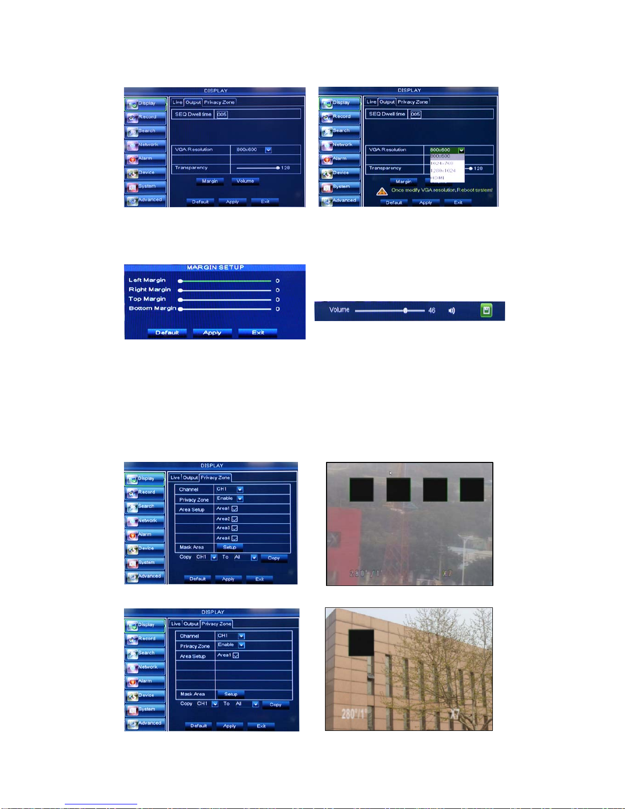
5.3.1.2 Output mode
Go to [Main menuDisplayOutput] to enter into the output set interface shown as Picture 5-5.
Transparency: allow you adjust menu’s transparency, and its range is 1~128.
Margin: allow you adjust the whole screen’s margin. Details operations please refer to the Picture 5-7.
Volume: allow you adjust the DVR volume shown as Picture 5-8.
5.3.1.3 Privacy Zone
The function Allow you setup privacy zone parameters according to Picture 5-9. Each channel could set
up to four privacy zones, and please follow below steps to set:
1. Select the area no (Area 1 ~ Area 4);
2. Click [Setup] to adjust position of mask area;
3. After finishing position adjust, click right key of mouse to return back [Privacy zone] interface;
4. Click [Apply] to save the above setting.
4/8CH
Picture 5-9 Picture 5-10
Picture 5-7
Picture 5-8
Picture 5-5 Picture 5-6
User Manual
19
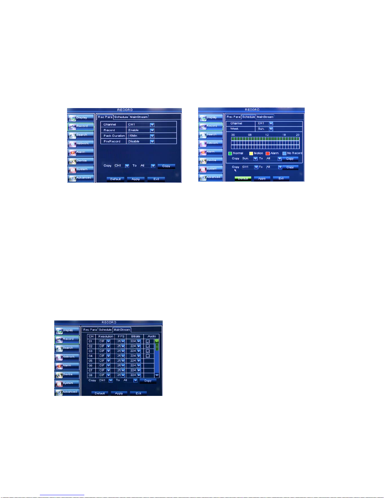
5.3.2 Record set
5.3.2.1 Record parameters
Go to [Main menuRecordRecord Para] to enter into the interface shown as Picture 5-11.
Channel: allow you setup the channel you desired.
Record: allows you set up record status (Enable/Disable) of each channel
Pack Duration: indicates maximum continuous record time (15, 30, 45 and 60 min).
Pre-record: Motion detection and I/O triggered record support Pre-record function.
5.3.2.2 Schedule
Click [Main MenuRecordSchedule] to enter into the interface shown as Picture 5-12.
[Channel] option allows you select one channel you desired.
To setup weekly schedules, tick-select the box of the record status you want (Alarm, General, or No
Record) and then click on each box in the schedule time line that you want this method to apply to. You can
use the [Copy – To] pull-down menus and Copy button to copy settings from one day to another day or all
days.
After you complete the schedule you activate it by clicking the [Apply] button.
You can also click on the Default button to use the system defaults.
Explanation: Under the <record> menu and <search> menu, original color stands for no record, “Red” stands
for alarm record, “yellow” stands for Motion record and “Green” stands for normal record.
5.3.2.3 Main Stream
Go to [Main menuRecordMain Stream] to enter into the interface shown as Picture 5-13.
Resolution: support D1, HD1 and CIF.(16CH not
supported D1)
Frame rate: PAL: 1-25 f/s ; NTSC: 1-30 f/s.
Bit rate: user could select the relative value by
pull-down menu.
Audio: When tick-selecting the option, system will
record video stream with audio simultaneously
Picture 5-11 Picture 5-12
Picture 5-13
This manual suits for next models
2
Table of contents
Other Bolide DVR manuals


