Bolide SVR9532S User manual

USER MANUAL
1
*4ch picture showed

USER MANUAL
1
Contents
CHAPTER 1 FUNCTIONAL DESCRIPTIONS AND FEATURES........................ 1
CHAPTER 2 OVERVIEW OF DVR......................................................................... 2
2.1 FRONT PANEL ...............................................................................................................2
2.1.1 Front panel for DVR with 4/8/16 channels.................................................2
2.2 REAR PANEL .................................................................................................................3
2.2.1 Rear panel for DVR with 4 channel and 1U case.....................................3
2.2.2 Rear panel for DVR with 8 channel and 1U case.....................................4
2.2.4 Rear panel for DVR with 16 channel and 1U case...................................5
2.3 REMOTE CONTROL.........................................................................................................6
CHAPTER 3 DVR CONNECTION.......................................................................... 7
3.1 HDD INSTALLATION .......................................................................................................7
3.2 IP CAMERA AND MONITOR CONNECTION...........................................................................7
3.3 POWER SUPPLY CONNECTION ..........................................................................................7
CHAPTER 4 DVR BOOT UP.................................................................................. 7
4.1 SYSTEM INITIALIZATION ...................................................................................................7
4.2 STARTUP WIZARD ..........................................................................................................8
4.3 MAIN INTERFACE ...........................................................................................................9
CHAPTER 5 DVR MENU...................................................................................... 10
POP-UP MENU .................................................................................................................10
5.1 MAIN MENU GUIDE ....................................................................................................11
5.2 MAIN MENU ..............................................................................................................12
5.2.1 PARAMETER.............................................................................................................12
5.2.2 Record Search.............................................................................................25
5.2.3 Device............................................................................................................32
5.2.4 PTZ and Cloud Storage..............................................................................33
5.2.5 System...........................................................................................................34

USER MANUAL
2
5.2.6 Advanced ......................................................................................................37
5.2.7 Shutdown......................................................................................................38
5.3 MENU LOCK ...............................................................................................................39
5.4 SPLIT MODE...........................................................................................................39
5.5 RECORD SEARCH..................................................................................................39
5.6 MUTE......................................................................................................................39
5.7 START SEQUENCE .................................................................................................39
CHAPTER 6 WEB APPLICATION MANAGER................................................... 40
6.1 ACTIVEXCONTROL DOWNLOAD AND INSTALLATION .............................................................40
6.2 WEB APPLICATION MANAGER LOGIN...............................................................................41
6.3 LIVE INTERFACE ...........................................................................................................41
6.3.1 Menu Bar......................................................................................................42
6.3.2 Playback........................................................................................................43
6.3.3 Remote Setting...........................................................................................47
6.3.4 Network.........................................................................................................53
6.3.5 Alarm..............................................................................................................55
6.3.6 Device............................................................................................................56
6.3.7 System...........................................................................................................58
6.3.8 Advanced ......................................................................................................60
6.3.9 Local Setting.................................................................................................62
6.3.10 Logout..........................................................................................................62
CHAPTER 7 APPENDIX....................................................................................... 63
7.1 TROUBLESHOOTING...............................................................................................63
7.2 USAGE MAINTENANCE ..........................................................................................64
7.3 SYSTEM CONNECTION DIAGRAM.....................................................................................65
7.4 ACCESSORIES ..............................................................................................................65

USER MANUAL
3
SAFETY INSTRUCTIONS
Please carefully read the following safety instruction so as to avoid personal injuries
and prevent the equipment and other connection devices from being damaged.
1. Power sources (note: please use the power supply attached or specified by the
manufacturer)
Never operate the equipment by using unspecified power supply.
2. Never push objects of any kind through openings of DVR
Never push objects of any kind through openings of DVR so as to avoid electric shock or
other accidents.
3. Do not put the equipment in the dusty environments.
Do not put the equipment in the dusty environments.
4. Do not place the equipment under rain or humid environment
Do not place the equipment under a humid environment. If the equipment is accidentally
in contact with water, please unplug the power cable and immediately contact your local
dealer.
5. Keep the surface of the equipment clean and dry
Use soft damp cloth to clean the outer case of DVR (do not use liquid aerosol cleaners)
6. Do not operate if any problems are found
If there are any strange smell or sound from DVR, unplug the power cable and contact the
authorized dealer or service center.
7. Do not try to remove the upper cover
Warning: Do not remove the cap of DVR so as to avoid electric shock.
8. Handle with care
If DVR does not work normally because of hitting on the hard object, please contact the
authorized dealer for repair or replacement.
9. Use standard lithium battery (Note: Use the batteries attached or specified by the
manufacturer)
After cutting off the power supply, if the system clock cannot continue to work, please
replace the standard 3V lithium battery on the main board.
Warning: Turn off DVR before replacing the batteries, or you may suffer from serious
electric shock. Please properly dispose of the used batteries.
10. Put the equipment in a place with good ventilation
The DVR system includes HDD, which produces large amount of heat during operation.
As a result, do not block the ventilation openings (on the top, bottom, both sides and the
reverse side) for cooling the system during operation. Install or put the equipment in the
place with good ventilation.
11. The attached power adapter can only be used for 1 set of DVR. Do not connect
more equipment, or DVR may be restarted repeatedly because of insufficient power
12. Keep equipment from liquids. Do not place beside objects containing water, such
as flower vase, on the equipment
1
Chapter 1 Functional Descriptions and
Features
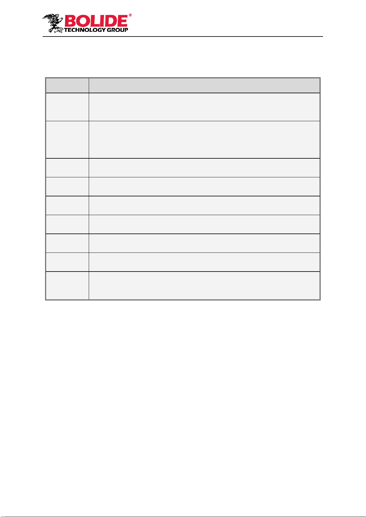
Function
Brief Description
Real time
monitoring
Support output by monitor, VGA and HDMI, support real-time monitoring by
web application manager and mobile phone, and support electronic amplifier,
multi-screen sequence and PIP display.
Recording
Support video compression standard of H.264. The video quality, resolution of
each channel and video frame rate are adjustable. Supports many recording
modes, such as start-up recording, timing recording, manual recording, alarm
recording, motion detection recording, remote recording, etc.
Record
storage
Support high capacity HDD with SATA port. The records can be stored
immediately in HDD.
Record
playback
Support single-channel or multi-channel search and playback by DVR or
network.
Record
backup
Backup records from DVR to U flash disk, mobile HDD and disk burner; or from
network to HDD.
Alarm
setting
Support alarm management of HDD and video input and the signal input from
external alarm apparatus.
Network
operation
Support authorized accessing of remote client to ensure the system security.
Mouse
operation
Support USB mouse operation to set system parameters conveniently and
efficiently.
PTZ control
Support PTZ decoder communicated through RS485. It can expand two kinds
of decoding protocol to realize PTZ and dome camera control. Support PTZ
preset auto cruise function.
Table 1-1
Features:
●H.264 video compression format, support 960H display resolution;
●G.711 audio compression format;
●Windows style graphic user interface and embedded real-time Linux 2.6 operation system;
● Warm menu prompt;
●Full real-time six functions (preview, recording, playback, backup, network monitoring, and
mobile phone monitoring);
● Supports dual-stream network transmission;
● Supports smart phone video monitoring;
● Supports electronic amplifying and channel sequence display;
●Video packaging time is adjustable;
●Multiple alarm modes;
●USB2.0 port, support backup, burning, software upgrading, mouse operation, etc;
● Supports infra-red remote control;
●Supports multi-language;
● Supports automatic system maintenance;
2
Chapter 2 Overview of DVR
2.1 Front Panel
P.S: DVR is short for Digital Video Recorder Equipment.
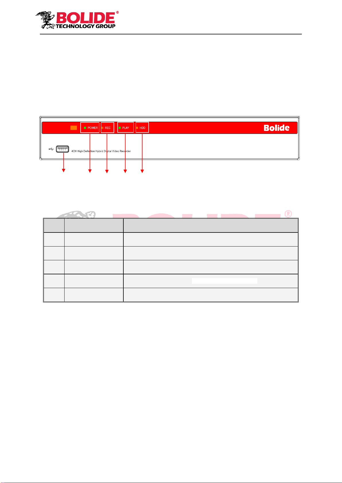
2.1.1 Front panel for DVR with 4/8/16 channels
SN
Physical Interface
Functions
1
USB 2.0
USB port
2
Power indicator
If the “Green” indicator is on, DVR is getting power normally.
3
Record indicator
If the “Red” indicator is on, recording is in session.
4
Play indicator
If the “Green” indicator is on, Playback is being executed.
5
HDD indicator
If the “Red” indicator is on, there is a functioning hard drive in the unit.
2
3
4
5
1
3
2.2 Rear Panel
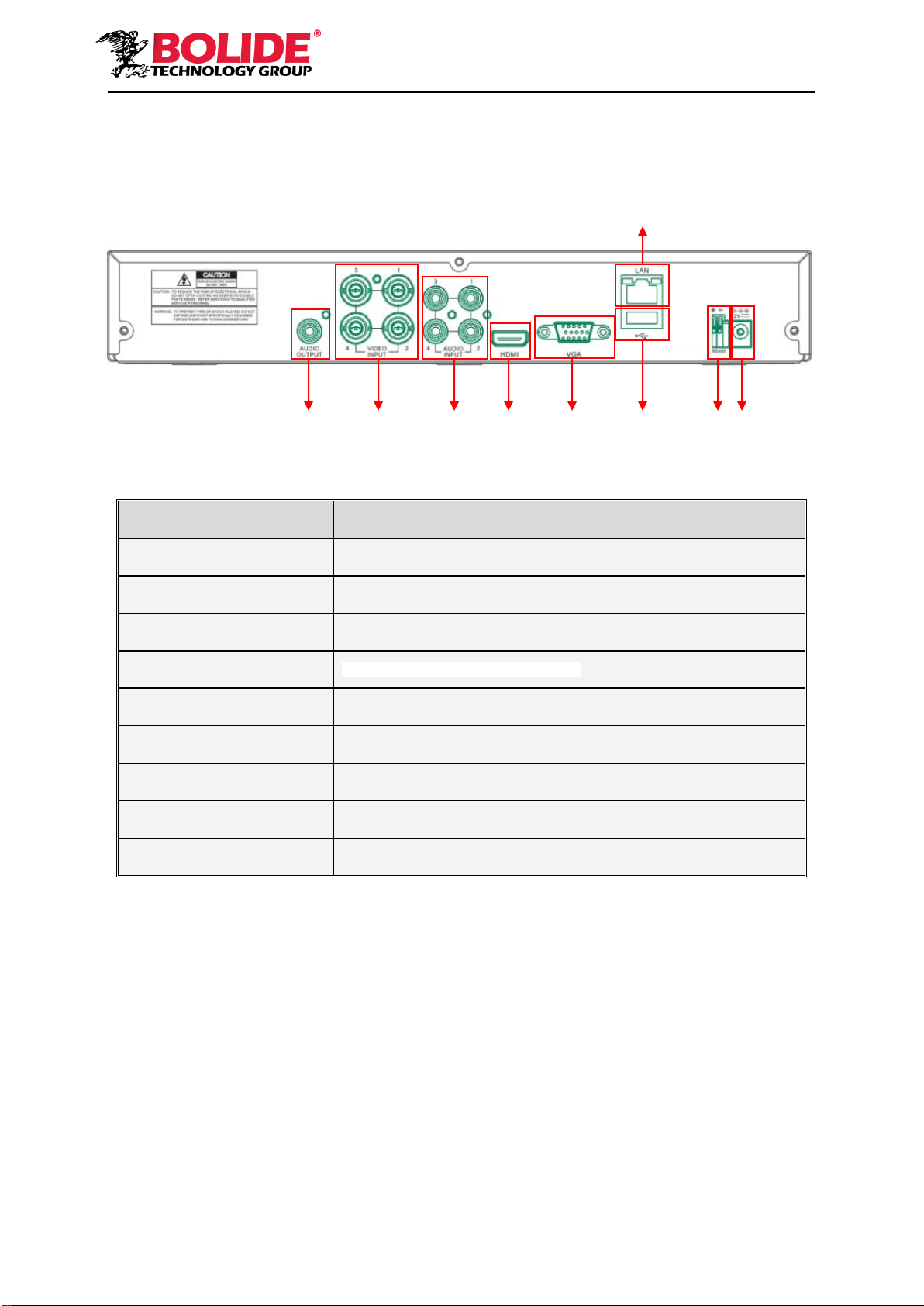
2.2.1 Rear panel for DVR with 4 channel and 1U case.
SN
Physical Interface
Connection
1
Audio output
Audio signal output, RCA port
2
Video output
Connect with monitor display output , standard BNC port
3
Audio input
Connect with CH1-4 audio input signals, RCA port
4
HDMI
Connect a high-definition video device.
5
VGA port
Connect with VGA display devices, such as PC monitor
6
LAN: Network port
Connect with LAN, Ethernet and RJ45 port.
7
USB 2.0
Connect with U flash disk, disk burner, and other USB storage devices
8
RS-485
RS485 port. Connect by referring to the interface definition below
9
Power port
Connect with the power supply DC12V 2A, attached with the machine
1
2
3
4
5
7
8
9
6
4
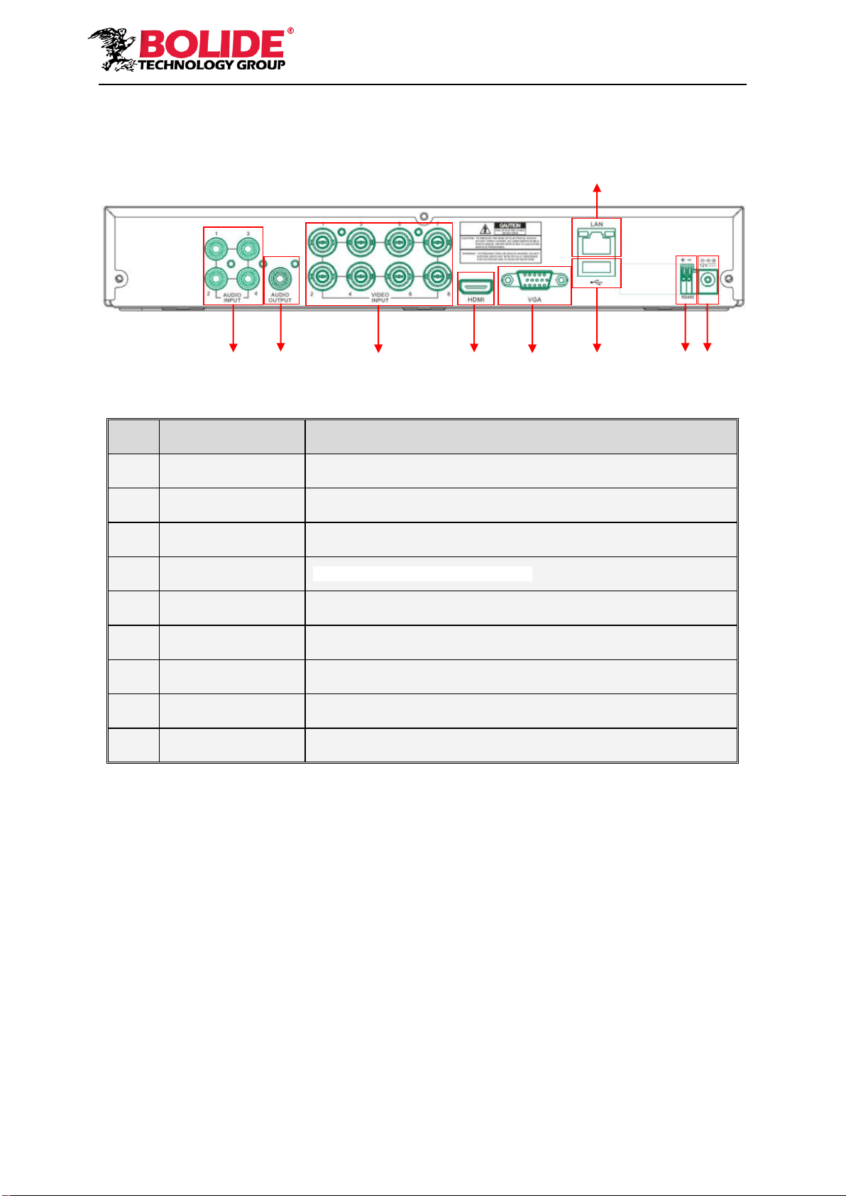
2.2.2 Rear panel for DVR with 8 channel and 1U case.
SN
Physical Interface
Connection
1
Audio input
Connect with CH1-4 audio input signals, RCA port
2
Audio output
Audio signal output, RCA port
3
Video input
Connect with monitor display output , standard BNC port
4
HDMI
Connect a high-definition video device.
5
VGA port
Connect with VGA display devices, such as PC monitor
6
LAN: Network port
Connect with LAN, Ethernet and RJ45 port.
7
USB 2.0
Connect with U flash disk, disk burner, and other USB storage devices
8
RS-485
RS485 port. Connect by referring to the interface definition below
9
Power port
Connect with the power supply DC12V 2A, attached with the machine
6
1
2
3
4
5
7
8
9
5
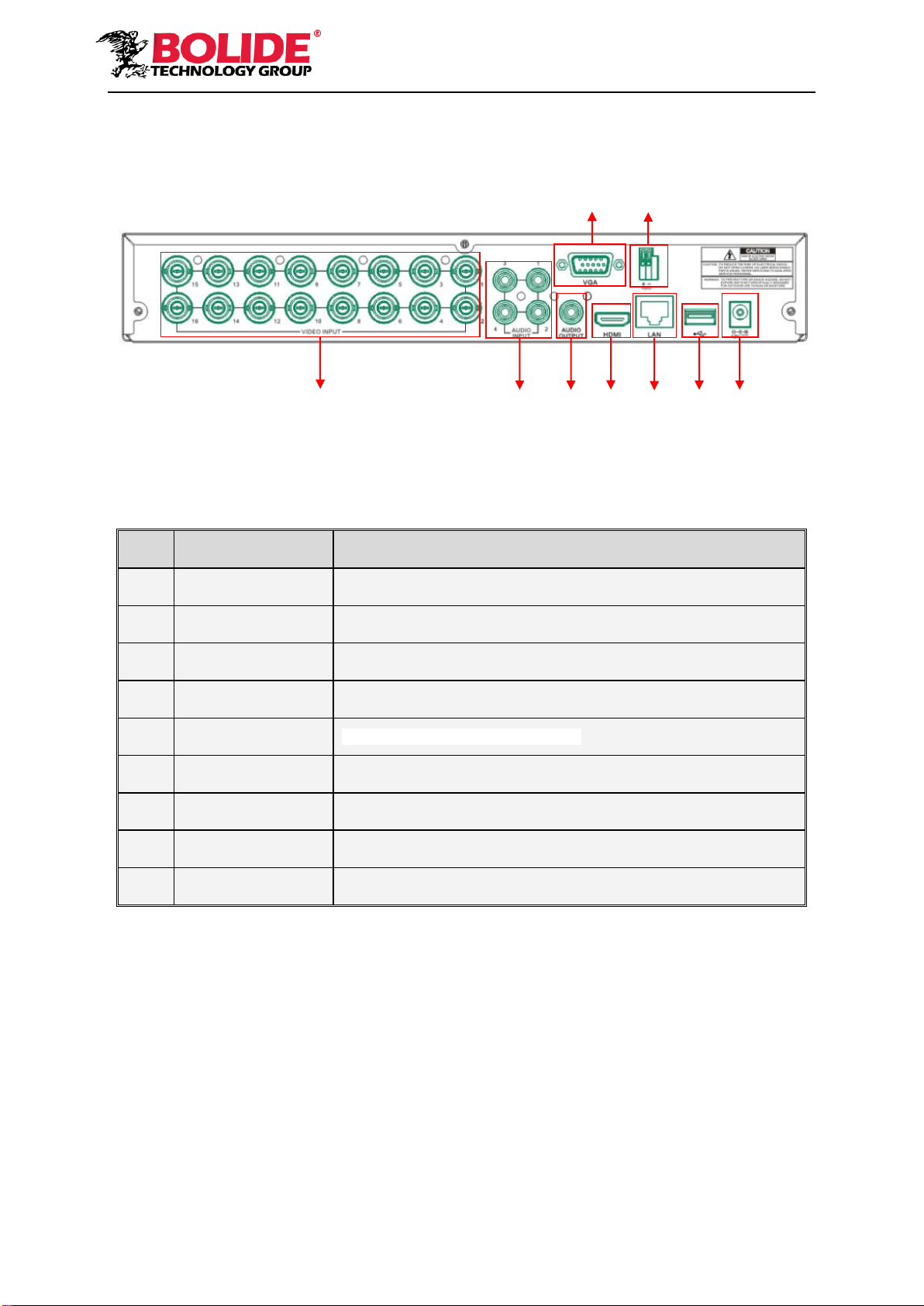
2.2.4 Rear panel for DVR with 16 channel and 1U case.
SN
Physical Interface
Connection
1
Video input
Connect with monitor display output , standard BNC port
2
Audio input
Connect with CH1-4 audio input signals, RCA port
3
Audio output
Audio signal output, RCA port
4
VGA port
Connect with VGA display devices, such as PC monitor
5
HDMI
Connect a high-definition video device.
6
RS-485
RS485 port. Connect by referring to the interface definition below
7
LAN: Network port
Connect with LAN, Ethernet and RJ45 port.
8
USB 3.0
Connect with U flash disk, disk burner, and other USB storage devices
9
Power port
Connect with the power supply DC12V 2A, attached with the machine
6
4
1
2
3
5
7
8
9
6
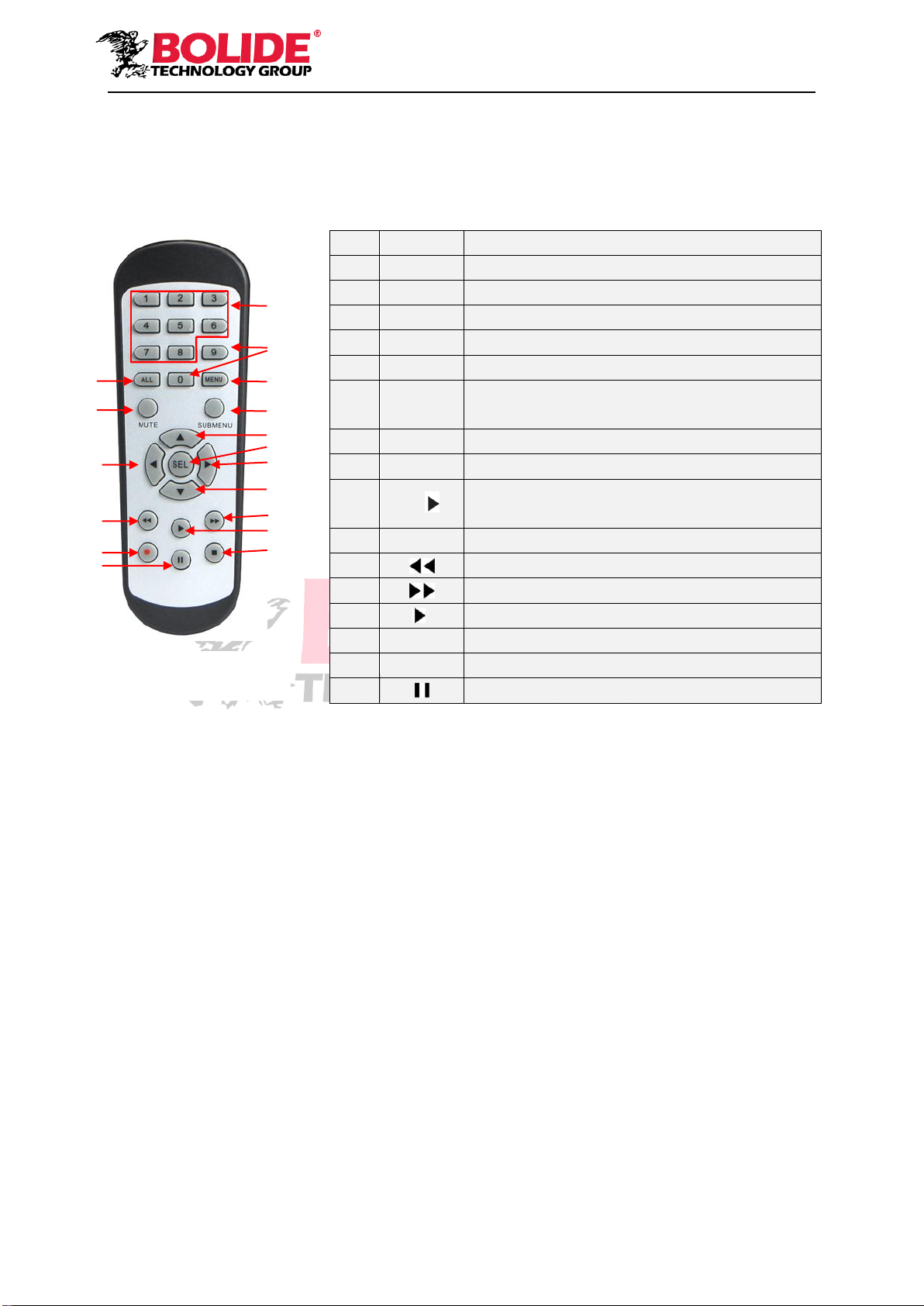
2.3 Remote Control
Table 2-3 Operation of remote control
Item
Key title
Key function
1
1-8
Channel select 1-8; Numeric key
2
9、0
Numeric key
3
ALL
Multiple display mode
4
Menu
Enter into Main menu/Exit
5
Mute
Mute On/off
6
Submen
u
Go to submenu
7
▲
Up arrow key, volume increase
8
SEL
Select key/Edit key
9
◄/
Left/Right key; Decrease/increase parameter
value of control bar.
10
▼
Down arrow key, Volume decrease
11
Rewind key
12
Forward key
13
Enter into record search menu / Play key
14
●
Record key
15
■
Stop manual record; stop playing
16
Pause/Sequence key
Table 2-3
1
2
3
4
5
6
7
8
9
10
9
11
12
13
14
15
16

7
Chapter 3 DVR Connection
3.1 HDD Installation
Caution: Please do not take out hard drive when DVR is running!
HDD Installation:
(1) Cut power, and then remove screws on both sides and rear panel and open DVR upper cover.
(2) Connect HDD data line and power line to the main board. Install the HDD to fix it on the bracket
and then connect the HDD power line and data line.
(3) Put the upper cover back carefully
Note: If user requires higher performance HDD, it is strongly recommended to use special hard
drive for security.
3.2 IP Camera and Monitor Connection
DVR video output signals are transmitted to VGA monitor or HDMI monitor by VGA or HDMI
cable and DVR video can be monitored (Refer to section 1.2 Rear Panel). Refer to Chapter 6
System Connection Diagram.
3.3 Power Supply Connection
Please use attached power adapter to connect DVR. Before power on, make sure the cables on
the audio and video I/O ports and network port are well connected. For audio ports, please use
microphone and other audio devices together with BNC connectingline toinput or output audio signals.
Chapter 4 DVR Boot up
4.1 System Initialization
After connecting the power cable of DVR to wall outlet and pressing the power button, you will
enter into the DVR system initializing screen shown as Picture 4-1.
Picture 4-1
Note:The illustration in the user
manual may not be the same as the
menu interface in your monitor. All
the illustrations are only for users’
reference.
8
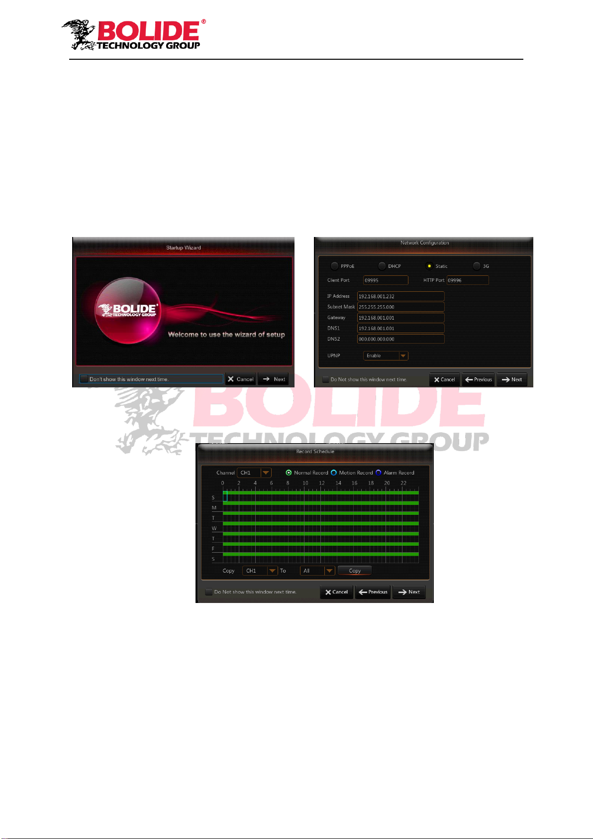
4.2 Startup Wizard
After DVR startup is completed, the startup wizard will be displayed. If you do not want to
change any setting, you may click “Don't show this window next time” to cancel, as shown in
Picture 4-2.
Wizard setting menu includes: Homepage, Network setup, Record Schedule and HDD.
1. Homepage and network setup. In network setup page, user may set the network environment of
DVR, as shown in Picture 4-3
Picture 4-2 Picture 4-3
2. Record Schedule (Picture 4-4). It can set recording time and scheduled recording of DVR.
Picture 4-4

9
3. HDD Management (Picture 4-5). It supports HDD format and overwrite type.
Picture 4-5
4.3 Main Interface
Picture 4-6
Note: When internal HDD is not connected to DVR, the character “H” will appear on the lower part
of the main interface and accompany buzzer alarm. If you want to disable the buzzer alarm, please
enter into [EventAlarm] to disable HDD loss alarm, HDD space insufficiency alarm and set alarm
output to “off”.

10
Chapter 5 DVR Menu
Pop-up Menu
After finishing system initialization, click right key of mouse on preview interface or slide the
mouse to the bottom of screen to enter into Pop-up Menu. Now you could perform parameter
setting and operate on Main Menu, Multi-screen, Auto Cruise, Record Search, Sequence, Volume
setting and Brightness setting, shown as Picture 5-1.
The options in the pop-up menu may be varied slightly according to different parameter
settings and application environment. The options in the menu will be explained in detail in the
following chapters.
Picture 5-1
11
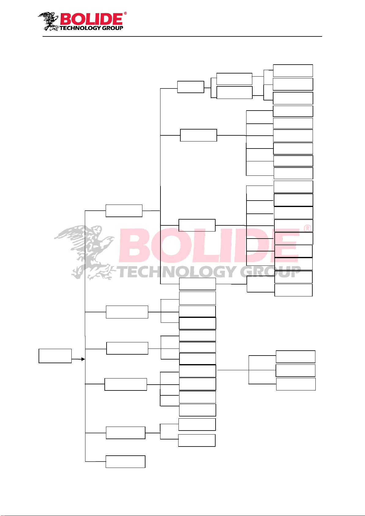
5.1 Main Menu Guide
System
Record
channel
Network
Shutdown
Main Menu
Parameter
Alarm
Record Search
Device
Schedule
Mainstream
FTP
Email
Substream
Email
Schedule
DDNS
RTSP
Motion
Alarm
PTZ
Cloud Storage
Advanced
Maintenance
Events
HDD
substream
Mobilestream
Capture
Display
Analog
IP Channels
Live
Output
Private Zone
Record
Events
General
Picture
General
Users
Info
Log
DST
General
NTP
Network
12
5.2 Main Menu
Picture 5-2
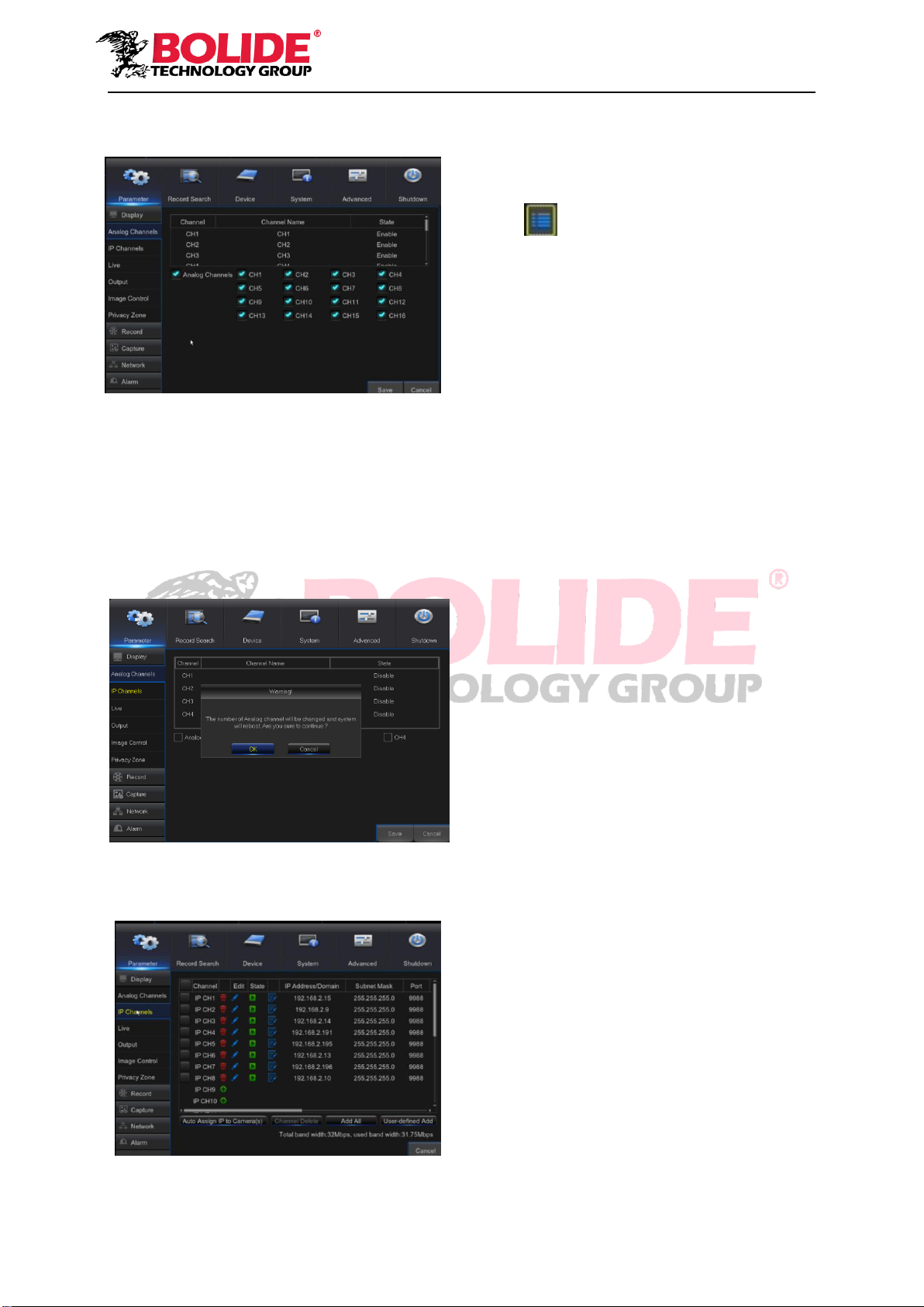
5.2.1 Parameter
1. Analog Channels
Go to “Main Menu”→“Parameter”→“Analog Channel”。As shown in picture 5-3
Can be increase/decrease the number of analog channel,System will need to reboot to correct
configuration parameters。
Picture 5-3
2. IP Channels
Picture 5-4
On LIVE mode, click the mouse button,
or [Menu] button on the remote controller, or
click [ ] icon on the toolbar to enter the
main menu screen, as shown in Picture 5-2
If system interface is locked, refer to
section 5.3 to unlock by inputting password.
In Main Menu mode, you can make
settings for Parameter, Record Search,
Device, System, Advanced and Shutdown.
13
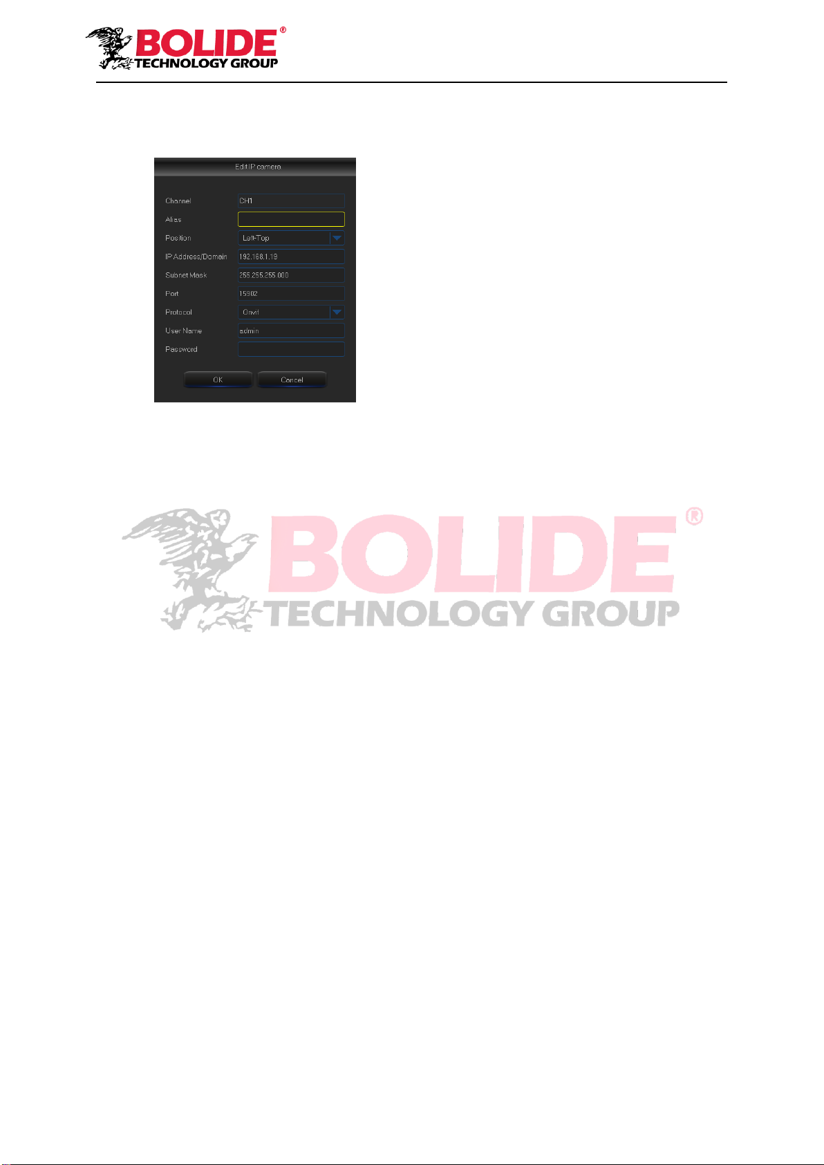
Picture 5-5
Channel:IPC camera channel
Edit:Modify the name and location of channels, change other IPC or protocols, etc, as shown
in Picture 5-5
State:Display IPC on-line state
IP address:Modify IP address of IPC camera.
IP Address/Domain:IP address of the IPC connected of the channel
Subnet Mask:IPC camera subnet mask
Port:Connection port number of the currently set IPC.
Manufacturer:Manufacturer for different IPC
Device type:Add IPC with different protocols.
Protocol:The selected access protocol for IPC to connect to NVR
MAC Address:Physical address for device
Software:Display current version of IPC.
14
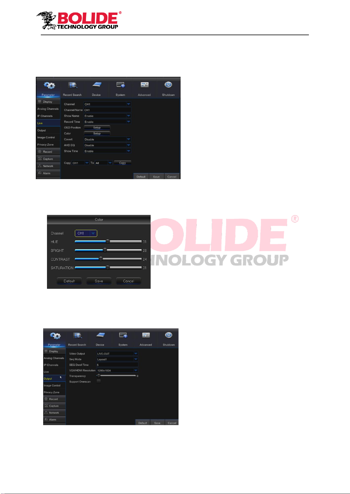
3. Live
Go to “Main Menu” →“Parameter” →“Display” →“Live” to enter into the interface shown as
Picture 5-6.
Picture 5-6
Picture 5-7
4. Output
Go to “Main Menu”→ “Parameter”→ “Display”→ “Output” to enter into the interface shown as
Picture 5-8.
Picture 5-8
Video Output: Live Output
Sequence Mode: Set sequence mode
SEQ Time: Sequence time is set 5 seconds
by default. User may set it as required
VGA/HDMI Resolution: For VGA output or
HDMI output, the optional resolution include
1024×768, 1280×1024, 1440×900, 1280
×720, 1920×1080
Transparency: Adjust menu transparency
in the range of 0--128.
Support Overscan: Supports HDMI overscan
Channel: Select the channel in the
drop-down list.
Channel Name: Channel name, support up
to 8 characters or 4 Chinese characters.
Show Name: Showing Channel name
Record Time: Enable or disable displaying
system time in recording.
OSD Position: Adjustment the position of
channel name and time display
Color: Click “Setup”to enter into the color
setting page (Picture 5-7)
Covert: Enable/Disable Video hiding
AHD EQ: Switch of AHD signal equalizer
Show Time: Enable or disable the system
time display in the live interface.
Copy: Copy the parameters in the channel
to any other channel or all channels.
Adjust the brightness, hue, contrast and
saturation of the image in selected channel in “Live”
interface.
Note:To modify the parameter value in sub-menu and
make it effective, click “Save” after modification and a
dialog box with message “parameters have been
successfully saved” will pop up. Click “OK” in the
interface and click “Exit” to exit the menu. If you want
to cancel the modification, click “Cancel” to exit.

15
5. Private Zone
Go to “Main Menu” → “Parameter” → “Display” → “Private Zone” to enter into the interface
shown as in Picture 5-9.
Privacy Zone is for setting some invisible parts in the selected channel, as shown in Picture
5-6 and Picture 5-10.
1. Select the number of the zone to be set (maximum 4 zones can be set for single channel)
2. Click “Setup” to adjust the position of the zone.
3. After finish setting, right click the mouse to return to the “Privacy Zone” page.
4. Click “Save” to save the setting.
6. Record
Go to “Main Menu” →“Parameter”→“Record” →“Record” to enter into the interface shown
as Picture 5-11.
Picture 5-11
Channel: Set the desired channel in the
drop-down menu
Record Switch: Enable/disable record
Pre Record: Enable to pre-record
motion detection or I/O trigger record.
Picture 5-9 Picture 5-10
16
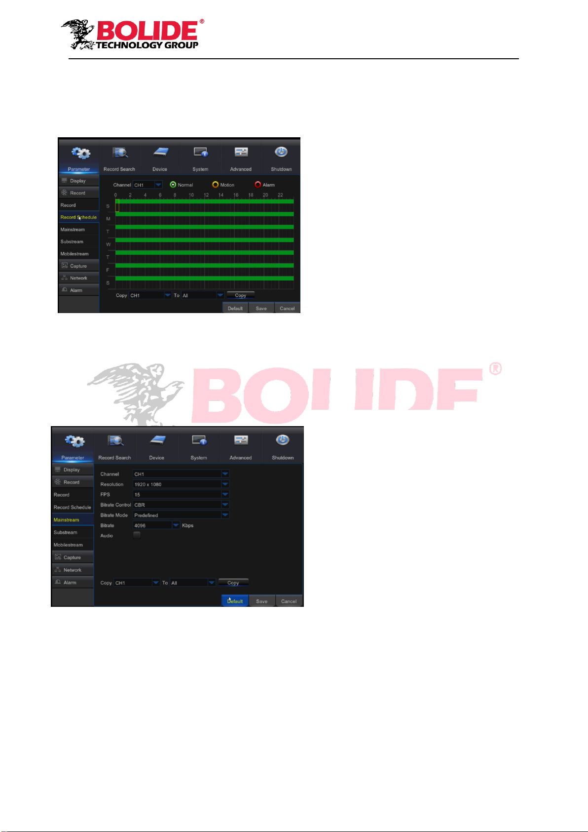
7. Record Schedule
Go to “Main Menu” → “Parameter” → “Record” → “Record Schedule” to enter into the Record
Schedule interface to set record schedule for DVR, as shown in Picture 5-12.
Picture 5-12
8. Mainstream
Go to “Menu” → “Parameter” → “Record” → “Mainstream” to enter into the menu interface, as
shown in Picture 5-13.
Picture 5-13
Select the channel and the date to be set.
One week’s schedule can be set.
The record schedule of the current
channel can be copied to another channel, or
all channels.
Note:
1. In the Record menu and Record Search
menu, No Color stands for no record;
2. “Green” stands for normal record and
“yellow” stands for motion record
3. “Red” stands for alarm record,
“Main Menu”→ “Record” → “Mainstream”
Channel: Support Analog and IPC. Select a
resolution, save and exit main menu. The
system will automatically restart for system
to take effect.
Resolution :464*240/928*240/928*480/1280
*720/1920*1080
Note: In AHD series, the supported record
resolution includes 960H/720P/1080P;
FPS:PAL: 1—25FPS NTSC:1-30FPS
Bitrate Control: Select either constant (CBR)
/ variable (VBR) bit rate
Bitrate Mode: Select default/custom bit rate
Bitrate: Bit rate setting
Audio: Enable audio recording
This manual suits for next models
4
Table of contents
Other Bolide DVR manuals


Popular DVR manuals by other brands


Daewoo
Daewoo DX-C811N operating instructions

Evolveo
Evolveo Detective D04 Quick setup guide

TBK vision
TBK vision TBK-NVR2100 Series user manual

Nuvico
Nuvico EasyNet ED-P400 installation manual

TiVo
TiVo Bolt Audio & Video Settings

EverFocus
EverFocus PowerPlex EDR1600 Administrator's guide and operating instructions

Digital Watchdog
Digital Watchdog VMAXip PLUS DW-VP9P quick start guide

HIK VISION
HIK VISION DS-8100-S Series user manual

Hyper Vision
Hyper Vision DVR-800 installation guide

HIK VISION
HIK VISION Network Video Recorder user manual

X-Vision
X-Vision XDVR user guide

HIK VISION
HIK VISION DS-7100NI-SL series Quick operation guide