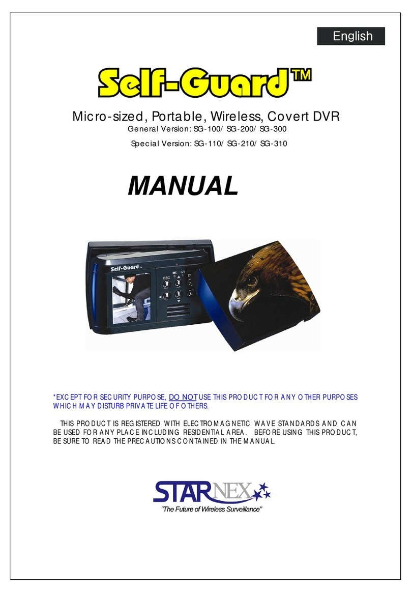
Starnex SG-3000 User manual

The Smallest, Wireless, Mobile, and Covert DVR in the World
SELF-GUARDTM
(Professional Version: SG-1000, SG-2000, and SG-3000)
User’s Guide
Thank you for purchasing this Self-Guard product.
- Before using it, be sure to read the precautions contained in the User’s Guide.
- Keep the User’s Guide in a safe place for future reference.
- For the most up-to date information about this product, visit our official website
at http://www.STARNEXinternational.com/.
Unpacking
Check to make sure that all of the items shown below are included with your Self-
Guard. If something is missing, contact your dealer as soon as possible.

3
– Contents –
INTRODUCTION ----------------------------------------------------------------------------------- 6
1. Precautions --------------------------------------------------------------------------------------- 6
2. Features ------------------------------------------------------------------------------------------- 11
3. Specifications and Comparison of each Model ------------------------------------------ 13
4. Applications --------------------------------------------------------------------------------------- 15
QUICK START GUIDE -------------------------------------------------------------------------- 16
1. Charging the Battery ---------------------------------------------------------------------------- 16
2. Turning the Self-Guard On and Off --------------------------------------------------------- 16
3. To Configure Clock Settings ------------------------------------------------------------------ 16
4. To Record a Moving Image ------------------------------------------------------------------- 17
5. To Playback a Moving Image ---------------------------------------------------------------- 18
GETTING READY -------------------------------------------------------------------------------- 22
1. Self-Guard -------------------------------------------------------------------------------------- 22
2. Docking Station -------------------------------------------------------------------------------- 26
GENERAL GUIDE -------------------------------------------------------------------------------- 28
I. Functions ------------------------------------------------------------------------------------------ 28
I-1. RECORD ------------------------------------------------------------------------------------ 28
I-2. CAMERA ------------------------------------------------------------------------------------ 30
I-3. SEARCH ------------------------------------------------------------------------------------- 31
I-4. OPTION -------------------------------------------------------------------------------------- 37
A. Camera Set -------------------------------------------------------------------------------- 38
B. Record Set --------------------------------------------------------------------------------- 40
C. Search Set --------------------------------------------------------------------------------- 47
D. Date/Time Set ---------------------------------------------------------------------------- 49
E. Remote Set ------------------------------------------------------------------------------- 50
4
F. Sensor Set --------------------------------------------------------------------------------- 53
G. USB Set ------------------------------------------------------------------------------------ 55
H. MEMORY Set ----------------------------------------------------------------------------- 57
I. Others --------------------------------------------------------------------------------------- 58
a. Password Set ------------------------------------------------------------------------- 59
b. EXT MON Set ------------------------------------------------------------------------ 61
c. Power Set ------------------------------------------------------------------------------ 62
d. Alarm Set ------------------------------------------------------------------------------- 65
e. Upgrade --------------------------------------------------------------------------------- 69
f. Default Set ----------------------------------------------------------------------------- 70
g. SG Name ------------------------------------------------------------------------------- 70
I-5. TRANSMIT ----------------------------------------------------------------------------------- 71
I-6. BLUETOOTH (SG-3000 Only) ------------------------------------------------------------- 72
II. Remote Access and Data Search/Playback Program --------------------------------- 77
II-1. How to Install ------------------------------------------------------------------------------- 78
II-2. Remote Monitor and Save -------------------------------------------------------------- 84
II-3. Remote File Playback -------------------------------------------------------------------- 85
II-4. Remote File Copy ------------------------------------------------------------------------- 86
II-5. Data Search and Playback ------------------------------------------------------------- 87
II-6. Other Functions --------------------------------------------------------------------------- 88
Trouble Shooting Guide ----------------------------------------------------------------------- 92
(*SG is short for Self-Guard)

5
<< Important Notice >>
9The contents of this manual are subject to change without notice.
9STARNEX CO., LTD. has the responsibilities as the manufacturer of Self-
Guard to tell to each distributor that using the Self-Guard unit in the public
domain may be in violation of federal privacy statues.
9STARNEX CO., LTD. assumes no responsibility for any damage or loss
resulting from the use of this manual.
9STARNEX CO., LTD. assumes no responsibility for any loss or claims by third
parties which may arise through the use of the Self-Guard.
9STARNEX CO., LTD. assumes no responsibility for any damage or loss
caused by deletion of data as a result of malfunction, repairs, or battery
replacement. Be sure to back up all import data on other media to protect
against its loss.
9Note that the example screens and product illustrations shown in this User’s
Guide may differ somewhat by the screens and configuration of the actual
product.
9The buttons and functions, which are not explained in this manual, are aimed
to improve the functions in the future.
9The features of this product can be changed at any time without notice for the
purpose of improvement of the product.
<< Copyright Restrictions >>
Except of the purposes of your own personal use, unauthorized copying of
snapshot files, movie files, and audio files violates copyright laws and international
contracts.
Distribution to third parties of such files over the Internet without permission of the
copyright holder, whether for profit or for free, violates copyright laws and
international contracts.
6
INTRODUCTION
1. Precautions
General Notice
¾The adaptor of this product can be used for both 110V and 220V.
¾Never try to open the case of the Self-Guard or attempt your own repairs.
High-voltage internal components create the risk of electric shock when
exposed. Always leave maintenance and repair work up to a STARNEX
authorized service center.
¾Never look at the sun or other bright light through the LCD screen. Doing
so can damage your eyesight.
¾Keep the small parts and accessories of this Self-Guard out of the reach of
small children. If swallowed accidentally, contact your physician
immediately.
¾Keep the Self-Guard away from water and other liquids, and never let it get
wet. Moisture creates the risk of fire and electric shock. Never use the Self-
Guard outdoors in the rain or snow, at the seashore or beach, in the
bathroom, etc.
¾Should foreign matter or water ever get into the Self-Guard, immediately
turn it off. Next, remove the Self-Guard’s battery and/or unplug the AC
adaptor power cord from the power outlet, and contact your dealer or
nearest STARNEX authorized service center. Using the Self-Guard under
these conditions creates the risk of fire and electric shock.
¾Should you ever notice smoke or a strange odor coming out of the Self-
Guard, immediately turn it off. Next, taking care you do not burn your
fingers, remove the Self-Guard’s battery and/or unplug the AC adaptor
power cord from the power outlet, and contact your dealer or nearest
STARNEX authorized service center. Using the Self-Guard under these
conditions creates the risk of fire and electric shock. After making sure
there is no smoke coming from the Self-Guard, take it to your nearest
STARNEX authorized service center for repair. Never attempt your own
maintenance.
¾Never use the AC adaptor to power any other device besides this Self-

7
Guard. Never use any other AC adaptor besides the one that comes with
this Self-Guard.
¾Never cover the AC adaptor with a quilt, blanket, or other cover while it is
in use, and do not use it near a heater.
¾At least once a year, unplug the AC adaptor power cord from the power
outlet and clean the area around the prongs of the plug. Dust build up
around the prongs can create the risk of fire.
¾If the Self-Guard’s case should ever become cracked due to dropping it or
otherwise subjecting it to rough treatment, immediately turn it off. Next,
remove the Self-Guard’s battery and/or unplug the AC adaptor power cord
from the power outlet, and contact your dealer or nearest STARNEX
authorized service center.
¾Never use the Self-Guard inside of an aircraft or in any other area where
its use is prohibited. Doing so creates the risk of accident.
¾Physical damage and malfunction of this Self-Guard can cause the data
stored in its memory to be deleted. Always keep backup copies of data by
transferring them to USB memory stick or USB Hard Disk.
¾Never remove the battery, disconnect the AC adaptor from the Self-Guard,
or unplug the AC adaptor from the wall socket while a moving image is
being recorded. Doing so will not only make storage of the current image
impossible, it can also corrupt other image data already stored in the file
memory.
Test for proper operation before using the Self-Guard
Before using the Self-Guard to record important moving images, make sure
you first record a moving image and check the result to ensure that the Self-
Guard is configured correctly and operating properly.
Data Error Precautions
Your Self-Guard is manufactured using precision digital components. Any of
the following creates the risk of corruption of data in file memory.
¾Removing the battery, flash memory card, or USB memory device while
the Self-Guard is performing a record or memory access operation.
¾Disconnecting the USB cable, removing the Self-Guard from the Docking
8
Station, or disconnecting the AC adaptor from the Docking Station while a
data communication operation is being performed.
¾Low battery power.
¾Other abnormal operations.
Any of the above conditions can cause an error. Follow the instructions
provided by this manual to eliminate the cause of the error.
USB Memory Device Precautions
You must connect the AC adaptor to the Self-Guard’s power input port to
supply 5 volts to the USB memory devices.
Do not insert or remove USB memory devices from the USB port in the Self-
Guard while recording or searching. When you remove the USB memory
device from the Self-Guard, you must exit from “RECORD” or “SEARCH”
mode, and select “REMOVE USB” from main menu and press [ENT]
button. After “REMOVE USB NOW” message appears on the LCD, you
can remove the USB memory device from the Self-Guard.
When you back up the Self-Guard’s data to your computer, first, copy the data
in the Self-Guard to a USB memory device, and then insert that USB memory
device to the USB port in the computer to copy the data in USB memory
device to the computer. Use only the USB cable provided in the package. It
may cause damage to both the Self-Guard and the computer if you connect
the Self-Guard to the computer using other USB cables directly.
Flash Memory Card Precautions
Do not insert or remove the memory card from the Self-Guard while recording
or searching. If you want to remove the memory card from the Self-Guard,
then you must exit from “RECORD” or “SEARCH” mode, before removing the
memory card from the Self-Guard.
Automatic Power-Off Function
The Self-Guard automatically turns off the power or goes into the power-
savings mode if you don’t press any button for a certain amount of time (1-9
minutes). This does not indicate malfunction of the system.

9
In “RECORD” and “TRANSMIT” modes, Self-Guard turns off only the LCD,
battery status LAMP, and recording status LAMP to save the battery. But, in
the rest of the modes except for “RECORD” or “TRANSMIT”, it turns off the
power completely. Set the time to 0 to deactivate “AUTO POWER OFF”
function.
Caution: To maximize the life of the battery, do not turn off “AUTO
POWER OFF” function.
Operating conditions
This Self-Guard is designed for use in temperatures ranging from -10℃to
50℃(14℉to 122℉).
Do not expose this product directly to intense sun-light or heat.
Do not expose to rain or extreme humidity or dirty environment.
Keep this product away from extreme vibration or any magnetic devices.
Only use the battery and adaptor provided by us.
Do not open the cover of this product. Otherwise, the warranty will be void.
Before using our product, read the user’s guide carefully and become familiar
with all the features and warnings associated with this product.
Do not touch this product with wet hands.
Condensation
¾When you bring the Self-Guard indoors on a cold day or otherwise expose
it to a sudden change of temperatures, there is the possibility that
condensation can form on the exterior or on interior components.
Condensation can cause malfunction of the Self-Guard, so you should
avoid exposing it to conditions that might cause condensation.
¾To keep condensation from forming, place the Self-Guard into the Carry-
Along Bag before moving it into a location that is much warmer or colder
than your current location. Leave it in the plastic bag until the air inside the
bag has a chance to reach the same temperature as the new location. If
condensation does form, remove the battery from the Self-Guard for a few
hours.
Lens
10
¾Never apply too much force when cleaning the surface of the lens. Doing
so can scratch the lens surface.
¾Dust or any other soiling of the lens can interfere with proper image
recording. You can remove dust particles from the lens surface by using a
lens blower to blow them off. Next, wipe the surface of the lens with a soft
lens cloth.
Others
¾The Self-Guard may become slightly warm during use. This does not
indicate malfunction.
¾If the exterior of the Self-Guard needs cleaning, wipe it with a soft, dry
cloth.
NOTE
This equipment has been tested and found to comply with the limits for a
Class B digital device, pursuant to Part 15 of the FCC Rules. These limits are
designed to provide reasonable protection against harmful interference in a
residential installation. This equipment generates uses and can radiate radio
frequency energy and, if not installed and used in accordance with the
instructions, may cause harmful interference to radio communications.
However, there is no guarantee that interference will not occur in a particular
installation. If this equipment does cause harmful interference to radio or
television reception, which can be determined by turning the equipment on
and off, the user is encouraged to try to correct the interference by one or
more of the following measures:
¾Reorient or relocate the receiving antenna.
¾Increase the separation between the equipment and receiver.
¾Connect the equipment into an outlet on a circuit different from that to
which the receiver is connected.
¾Consult the dealer or an experienced radio/TV technician for help.
¾Changes or modifications not expressly approved by the party responsible
for compliance could void the user's authority to operate the equipment.

11
2. Features
Self-Guard is an extremely small digital recording system, which can digitally compress,
store, search, and transmit/receive information such as, image and audio captured by
the camera and microphone.
The Self-Guard defines all the existing technologies of the DVR/CCTV combination, as
well as integrating other revolutionary security innovations: Remote Access and
Bluetooth.
You can monitor any place from anywhere, because the Self-Guard transmits image
and audio to remote areas using wireless transmit technology. By applying this
technology, Self-Guard is the Ubiquitous security system.
You can connect to the Self-Guard by the internet with a computer, and view the live
images of the Self-Guard. Also, you can copy the files saved in the Self-Guard to your
local computer and playback.
Self-Guard is a user-friendly system, and a necessity in these days when security
comes to our top priority.
zTotal Solution in Security System for its most up-to-date technology
zUnlimited Fields of Application
zEasy Covert Operation using the Concealing Case, Button/Pen Camera etc.
zBuilt-In 1 (up to 2) CCD Color Camera
z2 Built-In Microphones and 1 speaker
zBuilt-In color LCD (1.8 Inch) for Immediate and Easy Search / Playback
z4 Color Camera Input Ports
z3 Sensor Input/Output Ports
z1 Microphone Input Port
z1 TV (Audio/Video) Output Port
12
zIntelligent Algorithm for Motion and Audio Detection
zRemote Monitor, Copy, and Record via LAN
zWireless Transmit and Receive of Digitalized Audio/Video Data
zSubminiature Size (Less than a Cigarette Pack)
zDurable Design for Impacts
zProgrammable Settings for the Option in the Menu – You can configure
different values for every option in the menu.
zSnapshot Mode
zBuilt-In (128MB) Flash Memory - Free of Data Loss, Images can be recorded
without using a memory card
zMemory Card for Memory Expansion
zLong Recording Time and Data Back-up with the External USB HDD or USB
Memory Stick
zLong Battery Life (A Low-power technology to provide more recording and
playback between charges.)
zUser-friendly Operation

13
3. Specifications and Comparison of each Model
3.1 Specifications
SECTION DESCRIPTION REMARKS
Internal Storage Device Built-In Flash memory: 128 MB (up to 1 GB)
Memory Expansion Flash Memory Card: 128MB – 1GB RS-MMC
Extensive Storage
Device & Data Backup USB Memory Stick, USB HDD
Built-In 1 CCD Color (up to 2EA) 307,200 pixels
Camera External NTSC/PAL (4EA)
Recording
Resolution NTSC/PAL up to 640 x 480 pixels
Display
Speed NTSC/PAL 25 fps
Recording
Speed NTSC/PAL 12 fps @240 x 240
pixels
Light Sensitivity
(Built-In Color Camera) 1 Lux under@f1.2 CCD
Audio Input/Output 2 Built-In Microphones and 1 Speaker,
1AudioInput
Audio
Detection
TV(A/V) Output Built-In Color LCD, Monitor(NTSC/PAL) 1.8 Inch
128x160 pixels
Search(Playback) Date/Time, Motion, Sensor
Compression Method Optimized Algorithm for Security
Storage Capacity
High Quality (1-2 days)
Medium Quality (2-5 days)
Low Quality (5-10 days)
128MB, @1fps,
240x240pixels
(Indoor Use)
Display Date/Time/Frame
Lens
(Built-In Color Camera) Angle(56 Degrees), Unlimited Focus Pin-Hole Lens
Motion Detection Digital Image Processing,
External Signal Input(PIR Sensor Etc.)
Remote Access LAN
Wireless Communication Bluetooth
Source of Power Rechargeable Li- Polymer Battery (3.7VDC,
1400mAh), Adaptor (5V DC, 2A)
Recording Time
(Battery)
Normal Mode (4.5 hours)
Power Saving Mode (up to 24 hours)
Ultra Power Saving Mode (up to 3 days)
Dimensions: 85(W) × 55(H) ×22(D) mm Weight(Including Battery) : 116g(4.09oz)
3.34(W) × 2.16(H) × 0.86(D) inch Humidity: Under 80%
Operating Temperature: -10 °C to + 50 °C (14°F to 122 °F)
14
3.2 Comparison of each Model
Functions SG-1000 SG-2000 SG-3000
Wireless Tx/Rx (Bluetooth) - - O
Audio Recording - O O
Video Recording O O O
Sensor Input O O O
Network Access O O O
Audio Input - O O
Video Input O O O
TV Output O O O

15
4. Applications
zHouse, Apartment (Residential Areas), Hotel, School/University Facility,
Daycare Center, Kindergarten
zLaboratory, Hospital, Law Office, Museum, Church, Public Library, Commercial
Buildings
zBanks, Jewelry Shop, Restaurants, Department Stores, Liquor Stores,
Convenience Stores, Book Store, Gas Station
zFactories, Construction Site, Farm, Powerhouse, Parks, Amusement Park,
Public Facility
zFire Department (Fire Fighters), Security Guards, Police Units (Police Officers),
Mailman, Jailor
zMilitary Base (Soldier), Anti-Terror, Special Agents, Airports, Bus Terminal
zTaxi, School Bus, Car, Traffic Signs/Signals, Airplane, Parking Lot, Cash
Transporting Truck, Subway
zCourts, Executive Office, Conference Rooms, Governmental Offices, Cultural
Property Controlling Office
16
QUICK START GUIDE
1. Charging the Battery
zLoad the battery into the Self-Guard.
zPlug in the AC adaptor directly into the power input port of the Self-Guard. Or,
place the Self-Guard onto the Docking Station to charge the battery.
2. Turning the Self-Guard On and Off
zPush [ENT] for 2 seconds to turn on the power.
zPush [ESC] for 2 seconds and release it to turn off the power.
3. To Configure Clock Setting
Be sure to configure the following setting before using the Self-Guard.
→
↓
1. Press [ENT] for 2 seconds to turn on the Self-Guard.
2. Use [ ]△and [ ] to s▽elect “4. OPTION” and press [ENT].
3. Use [ ]△and [ ] to select▽“D.DATE/TIME SET” and press [ENT].
4. Use [ ] and [ ]◁▷to move the cursor to month, date, year, and time.
RECORD
CAMERA
SEARCH
OPTION
TRANSMIT
BLUETOOTH
08/25/2005
A.CAMERA SET
B.RECORD SET
C.SEARCH SET
D.DATE/TIME SET
E.REMOTE SET
F. SENSOR SET
G.USB SET
H.OTHERS
DATE/TIME :
02/25/2005
16:51:55
TYPE : MM/DD/YY

17
5. Use [ ]△and [ ] to change the values for each one.▽
6. Use [ ] and [ ]◁▷to move the cursor to “DATE TYPE”.
7. Use [ ]△and [ ] to▽select one from 3 types. (DD/MM/YY, MM/DD/YY, YY/MM/DD)
8. Press [ENT] to register the settings and exit the setting menu.
(There are 3 ways to arrange the “DATE TYPE” setting, and it varies in different
geographic areas. The types will be changed in a regular sequence of (DD/MM/YY
ÆMM/DD/YY ÆYY/MM/DD) as you press [ ]△and [ ].▽
4. To record a moving image
Use [ ] and [ ] to select△▽ RECORD, and then press [ENT]. Then, it will appear with
the sight that’s being recorded as below and the Self-Guard starts to record images.
RECORD
CAMERA
SEARCH
OPTION
TRANSMIT
BLUETOOTH
08/25/2005
18
- Before you start to record, be sure to check from the LCD that the camera can
capture the sight where you want it to be recorded.
- Press [ESC] to stop recording and exit from the “RECORD” mode.
- If you are recording with more than one camera, you can choose either a
single-channel mode or a 4 channel mode by pressing [ ] button.▽
zREC AV: Indication of recording both A (Audio) and V (Video).
Shows “REC V” when recording the video only.
zCH #1: Camera channel number 1 being used for recording.
If it shows C1345, then ‘C’ indicates of camera and 1345 indicates
for camera channel numbers.
If it shows C1B123, then ‘C1’ indicates of camera number 1 and
‘B123’ indicates of Bluetooth channel 1, 2 and 3.
z15:49:24: current time.
z(12): elapsed recording time (12 minutes).
z43%: 43 percent of the total memory(Built-in, RS-MMC, USB) is being used
for recording.
5. To Playback a Moving image
Use [ ] and [ ] to△▽select “SEARCH”, and press [ENT]. Then the next screen appears
as below.
RECORD
CAMERA
SEARCH
OPTION
TRANSMIT
BLUETOOTH
08/25/2005

19
You can search the data either by A.MOTION/SENSOR or B.SENSOR.
A.MOTION/SENSOR- includes data saved by both motion and sensor detection
B.SENSOR- includes data saved by sensor detection only.
Use [△]and[▽] to select “A.MOTION/SENSOR”, and then press [ENT]. Then the next
screen appears as below.
The list of the month and the year, which has recorded data shows on the screen. All
saved data are arranged by the month and the year in a list. If there is no data saved
on a month, then that specific month will not be included on the list.
COPY: To copy all the data of the selected month to the selected memory device.
(If USB or RS-MMC memory device is not connected to the Self-guard, then the cursor
does not move to COPY.)
1/4: First of four pages of the list
Mon / Year
05 / 2005
11 / 2004
08 / 2004
COPY 1
/
4
A.MOTION/SENSOR
B.SENSOR
20
Select a Mon/Year, which includes the file you want to playback, and then press [ENT].
•Green Colored Date: There exists saved data.
•White Colored Date: There exists no saved data.
•Pink Colored Date: Cursor position
Use [ ] and [ ]◁▷to select the date you want, and then press [ENT]. Then the list of
saved data appears on the screen as below. If you want to view the previous month
then press [△] and press [ ]▽to view the next month.
PREV Go to the previous page
1/3 First of 3 pages
NEXT Go to the next page
LOCK Lock from deleting file
DEL Delete selected file
DELALL Delete all files for the selected date (except for ‘*.outx’ file)
COPY Copyaselectedfiletotheselectedmemory
10121401.out
13245101.outx
22433202.outx
12334503.snp
PREV 1/3 NEXT
LOCK DEL DELALL
COPY COPYALL
<< 2004[10] >>
Su Mo Tu We Th Fr Sa
1 2 3 4 5 6 7
8 9 10 11 12 13 14
15 16 17 18 19 29 21
22 23 24 25 26 27 28
29 30 31

21
COPYALL Copy all file of the selected date to the selected memory
There are three colors (blue, red, or green) for each file to indicate which memory is
used to save the file. The indications are as follow.
Color of file name Meaning
Blue colored file File is stored in built-in memory.
Red colored file File is stored in the memory card.
Green colored file File is stored in USB memory devices.
The name of the file is composed of hours, minutes, seconds and the camera’s channel
numbers. For example, ‘10121401.out’ means that the file has recorded for 10 hours 12
minutes and 40 seconds from channel number 1. For 13245101.outx,‘x’ means the file
is locked to protect from deleting. To lock or unlock the file, select “LOCK” and press
[ENT]. The locked files are not to be deleted before you unlock it. However, locked files
can be deleted if you do the format (“OPTION” mode →“H.OTHERS” →“d.DATA
FORMAT”). ‘*.out’ indicates that it is a file of a moving image. ‘*.outx’ indicates that it is
a locked moving images and ‘*.snp’ is a snapshot image.
After selecting the file that you want to view, press [ENT].
More details about viewing a moving image are in the General Guide.
22
GETTING READY
1. Self-Guard

23
Memory Card Slot: This is the place where you put in the standard RS-MMC memory
card. If you need to expand the memory from the built-in, internal memory, you can get
this from where you have purchased the Self-Guard. This product provides a memory
card, which lacks in memory.
Cautions: Do not insert or remove the memory card from the slot while recording or
searching. If you want to remove the memory card from the slot, then you must exit
from “RECORD” or “SEARCH” mode fir, before removing the memory card from the
slot.
Camera Hole 1 (Built-In): Self-Guard has one built-in CCD camera on the front side of
the Self-Guard. Be sure that this camera hole is not blocked to prevent from the Self-
Guard unable to record the images.
Camera Hole 2 (Optional): Self-Guard can be installed with another CCD camera on
the rear side to record images from the back of the Self-Guard.
Mic Hole 1 (Built-In): This is where a highly efficient microphone is installed on the
front side of the Self-Guard. Be sure that this hole is not blocked in order to record the
audio.
Mic Hole 2 (Built-In): Self-Guard has second built-in microphone on the rear side. Be
sure that this hole is not blocked in order to record the audio.
Battery Status & Charge Lamp: This lamp indicates how much of the battery is left.
Lamp with the green color indicates that the battery is full. The color of this lamp
changes into yellow when the battery is half full, and the red color means that the
battery is almost used up. If you connect the AC adaptor to the Self-Guard when the
battery is not full, then it automatically charges up the battery to its fullest. While
charging the battery, the lamp blinks with the green light. After charging is completed,
the lamp stops blinking and you will see the green light indicating that the battery is full.
Recording Status Lamp: This lamp is to check on the recording status. When the
Self-Guard is not in the “RECORD” or “TRANSMIT” mode, the color is green and the
24
color changes into red when the Self-Guard goes into recording or server mode. In the
“RECORD” or “TRANSMIT” mode, the color is still red if there is no motion detected by
the Self-Guard. But when the Self-Guard detects a motion, then the color turns into
yellow, and turns back to red. So if the Self-Guard continues to detect motions, then the
color alternates between red and yellow. If you turn on the audio detection function
(OPTION →H.OTHERS→c.POWER SET→7.AUDIO DET), and audio is detected,
then this lamp blinks with red color.
Control Buttons
ESC: This button is to go to the previous menu from the current menu, or is to cancel
the selected values.
ENT: This button is to go to the selected menu or to apply the changed values.
△:This button is used to move up in the menu or to enter into the image magnification
mode in “1.CAMERA”, “2.RECORD”, and “SEARCH”, or to select certain values from
the “OPTION” mode.
▽:This button is used to move down in the menu, or to enter into 4 channel mode, or
to select certain values from the “OPTION” mode.
◁:In the menu, this button is used to move to the left or to select certain values.
▷:In the menu, this button is used to move to the right or to select certain values.
External Antenna Port: This port is to connect external antenna for Bluetooth. You can
transmit data about 80 – 100 meters using the built-in antenna. If you use the high gain
external antenna, you can increase the transmit range up to several kilometers. And
the distance depends on the kind of antenna gain.
Battery Holder: When you load the battery into the Self-Guard, this place keeps a hold
of the battery to the Self-Guard’s body. In order to settle the battery in the Self-Guard,
you need to place the battery onto the back of the Self-Guard’s body, and push the
battery to the upper direction. If you want to detach the battery from the body, then
press this holder with your thumb, and pull it in downward direction.
Li-ion Battery: Rechargeable battery with 3.7 volts and 1400mAh.
Connector with Docking: This is the port where you connect the Self-Guard with the

25
docking station. Through this port, you can link the connectors in the docking station
with the functions in the Self-Guard. All the functions are included in the Self-Guard’s
body, and the docking station has only the connectors for the external cameras,
microphone, external monitor, sensors, power, USB, and the connector for LAN.
USB Port: You use this USB port when you want to save data for a long period of time
or need to back up saved data in the Self-Guard to the USB memory such as, USB
memory stick or USB hard disk. This port has the USB mastering function, so if you
connect either a USB memory stick or a USB hard disk into the Self-Guard, then it
automatically detects that and enables you to use those USB memories (USB memory
stick and USB hard disk) as a memory expansion or a back up memory.
You must connect the AC adaptor to the Self-Guard’s power input port to supply
5 volts to the USB memory devices.
Cautions: Do not insert or remove USB memory devices from the USB port in the Self-
Guard while recording or searching. When you remove the USB memory device from
the Self-Guard, you must exit from “RECORD” or “SEARCH” mode, and select
“REMOVE USB” from main menu and press [ENT] button. After “REMOVE USB
NOW” message appears on the LCD, you can remove the USB memory device
from the Self-Guard.
When you back up the Self-Guard’s data to your computer, first, copy the data in the
Self-Guard to a USB memory device, and then insert that USB memory device to the
USB port in the computer to copy the data in USB memory device to the computer. Use
only the USB cable provided in the package. It may cause damage to both the Self-
Guard and the computer if you connect the Self-Guard to the computer using other
USB cables directly.
Power Input: connector for the AC adaptor (DC 5V, 2A).
26
2. Docking Station
LAN Port: This is the port for the LAN, where you can connect to the Self-Guard with
your computer in remote places.
USB Port: This is the same USB port as in the Self-Guard’s body.
MIC, S1: MIC is where you put in the external microphone. S1 is the port number 1 for
the sensor input and output. Provided sensor cable has three wires. The white colored
wire is for S1, red colored wire is for MIC, and the striped wire is for the GND (Ground).
PWR, S2: PWR is where you get the power (below 300mA) from the battery (3.6 V –
4.2 V) of the Self-Guard or from the adaptor (5 V). If the adaptor is connected to the
Self- Guard, then it gets the power from the adaptor and the voltage is 5. If there is no
adaptor connected to the Self-Guard, then it uses the power from the battery and the
voltage is from 3.6 to 4.2. S2 means that it is the port number 2 for the sensor input
and output. Provided sensor cable has three wires. The white colored wire is for S2,
red colored wire is for PWR, and the striped wire is for the GND (Ground).
PWR, S3: PWR is where you get the power (below 300mA) from the battery (3.6 V –
4.2 V) of the Self-Guard or from the adaptor (5 V). If the adaptor is connected to the
Self- Guard, then it gets the power from the adaptor and the voltage is 5. If there is no

27
adaptor connected to the Self-Guard, then it uses the power from the battery and the
voltage is from 3.6 to 4.2. S3 means that it is the port number 3 for the sensor input
and output. Provided sensor cable has three wires. The white colored wire is for S3,
red colored wire is for PWR, and the striped wire is for the GND (Ground).
A/V OUT: This port is for the audio and video output. You can connect a TV or an
external monitor to the Self-Guard through this port, and you can see larger images
than you could from the internal LCD by enlarging the images. Provided TV output
cable has two wires. The yellow colored wire is for the audio output, and the red
colored wire is for the video output.
V1, 2: This port is for the video inputs. You can connect external cameras through this
port. Provided video input cable has two wires. The red colored wire is for the video
input 1, and the yellow colored wire is for the video input 2.
V3, 4: This port is for the video inputs. You can connect external cameras to the Self-
Guard through this port. Provided video input cable has two wires. The red colored wire
is for the video input 3, and the yellow colored wire is for the video input 4.
Power Input: It is the same as the power input in the Self-Guard’s body
Supporter: This supporter upholds the Self-Guard when you set it up on it.
Connector with Self-Guard: This is the connector in the Docking Station to connect
with the Self-Guard.
Caution: It may cause problems to this product if you insert video input and TV output
cable into the sensor In/Out ports.
28
GENERAL GUIDE
Power ON/OFF
Push [ENT] for 2 seconds to turn on the power.
To turn off the power, push [ESC] for 2 seconds and release it.
Main Menu
When you turn on the power of the Self-Guard, then a screen appears as below.
I. FUNCTIONS
I-1. RECORD
Select “RECORD” with the direction buttons and then press [ENT]. Then it shows the
screen that’s being recorded as below, and the Self-Guard starts to record images.
RECORD
CAMERA
SEARCH
OPTION
TRANSMIT
BLUETOOTH
08/25/2005
RECORD
CAMERA
SEARCH
OPTION
TRANSMIT
BLUETOOTH
08/25/2005

29
When the Self-Guard goes into the “RECORD” mode, then the color of recording status
LAMP changes into red from green. When the Self-Guard detects a motion, then the
color turns into orange. So if the Self-Guard continues to detect motions, the color
alternates between red and orange.
This function saves images from the cameras, sounds from the microphones and data
from the sensors. Before you start to record, be sure to check from the LCD that the
camera can capture where you would like to record. In “RECORD” mode, even under
the situation of the battery and adaptor power outage, if the power from either of the
two gets available to the Self-Guard, then the Self-Guard automatically turns on its
power, and returns to the “RECORD” mode. This function is very useful for the users
who are in remote places from their Self-Guard, and not able to control it immediately
when they need to.
zREC AV: Indication of recording both A (Audio) and V (Video).
Shows “REC V” when recording the video only.
zCH #1: Camera channel number 1 being used for recording.
If it shows C1345, then ‘C’ indicates of camera and 1345 indicates
for camera channel numbers.
If it shows C1B123, then ‘C1’ indicates of camera number 1 and
‘B123’ indicates of Bluetooth channel 1, 2 and 3.
z15:49:24: current time.
z(12): elapsed recording time (12 minutes).
30
z43%: 43 percent of the total memory(Built-in, RS-MMC, USB) is being used
for recording.
Press [ ] to view the images▽in single mode, or in 4 channel mode. Press [ESC] to
stop recording and exit from the “RECORD” mode.
You can access the image and audio of the Self-Guard, or copy off the Self-Guard’s
data by the network from a remote computer. In addition, you can access images and
audio of the Self-Guard or copy off the data in the Self-Guards by the wireless
communication method (Bluetooth) from a remote Self-Guard (SG-3000 only).
When you connect to the Self-Guard by the network, you need to know the ID and the
Password. And when you connect to the Self-Guard wirelessly, then you need to know
the Self-Guard’s Bluetooth ID.
I-2. CAMERA
Select “CAMERA” using the direction buttons and then press [ENT]. Then the next
screen appears in the LCD as below.
RECORD
CAMERA
SEARCH
OPTION
TRANSMIT
BLUETOOTH
08/25/2005

31
You can check on the camera’s recording location, and the operating status of it with
the Self-Guard’s LCD. When using multiple cameras, you can see up to 4 images
simultaneously from the LCD. Every time you press [▽] in “1.CAMERA” mode, the
image from each channel, which is turned on, appears in order. After the last channel
shows up on the screen, it changes into 4 channel mode automatically, and displays
four images from different cameras at once.
You can take a snapshot like with a digital camera by pressing [ ]▷in this mode. The
file name is ‘*.snp’. You can check on the snapshot file from “SEARCH” mode. In
“SEARCH” mode, after stopped from playing, you can go to magnification mode by
pressing [ ]△and then you can get a larger snapshot image by pressing [ENT]. The
image is magnified by 4 times (width x 2 and length x 2) for the 240x240 or the
320x240 pixels of resolutions. And if the resolutions are 480x480 or 640x480 pixels,
then they are magnified by 16 times (width x 4 and length x 4). You cannot magnify the
images in the 128x128 or 160x128 pixels of resolutions. In magnified state for the
images, you can use the direction buttons to move to certain portion in the screen.
Press [ESC] to escape from the magnification mode. You can use this magnification
mode in the case that “1.MON OUT” (“4. OPTION” mode →“H.OHERS” →“b.EXT
MON SET”) is set to OFF.
I-3. SEARCH
32
Use [ ] and [ ] to△▽select “SEARCH”, and then press [ENT]. Then the next screen
appears as below.
This function lets you to search the data saved by the motion detection of the image
and by the sensor detection, or you can search the data saved by the sensor detection
only.
A.MOTION/SENSOR- includes data saved by both motion and sensor detection
B.SENSOR- includes data saved only by motion detection
A.MOTION/SENSOR
Use [△]and[▽] to select “A.MOTION/SENSOR”, and then press [ENT]. Then the next
screen appears as below.
RECORD
CAMERA
SEARCH
OPTION
TRANSMIT
BLUETOOTH
08/25/2005
A.MOTION/SENSOR
B.SENSOR

33
All saved data are arranged according to the month and the year.
Month and the year show on the screen if there exists data saved for that month
Mon/Year: Indication of the data for each month and the year
07/2005: Data exists for the month of May of 2005
11/2004: Data exists for the month of November of 2004
08/2004: Data exists for the month of August of 2004
COPY: Copy all the data for the selected month to the selected memory
(If USB or RS-MMC memory device is not connected to the Self-guard, then the cursor
does not move to COPY.)
1/4: First of four pages of the list
By using the direction buttons, select the month and the year that you want to search
with, and press [ENT]. Then the next screen appears as below. If you want to view the
previous month then press [△] and press [ ]▽to view the next month.
Mon / Year
07 / 2005
11 / 2004
08 / 2004
COPY 1
/
4
<< 2004[10] >>
Su Mo Tu We Th Fr Sa
1 2 3 4 5 6 7
8 9 10 11 12 13 14
15 16 17 18 19 29 21
22 23 24 25 26 27 28
29 30 31
34
•Green Colored Date: There exists saved data.
•White Colored Date: There exists no saved data.
•Pink Colored Date: Cursor position
Use [ ] and [ ]◁▷to select the date you want, and then press [ENT]. Then the list of
saved files appears on the screen as below.
PREV Go to the previous page
1/3 First of 3 pages
NEXT Go to the next page
LOCK Lock from deleting file
DEL Delete selected file
DELALL Delete all file of the selected date (except for ‘*.outx’ file)
COPY Copy selected file to the selected memory
COPYALL Copy all file of the selected date to the selected memory
There are three different colors (blue, red, green) for each file name to indicate which
memory device is used to save the files. The indications are as follow.
Color of File Name Meaning
Blue colored file name File is stored in built-in memory.
Red colored file name File is stored in the memory card.
Green colored file name File is stored in USB memory devices.
The name of the file is composed of hours, minutes, seconds and the camera’s channel
numbers. For example, ‘10121401.out’ means that the file has recorded for 10 hours 12
minutes and 40 seconds from channel number 1. For 13245101.outx,‘x’ means the file
10121401.out
13245101.outx
22433202.outx
12334503.snp
PREV 1/3 NEXT
LOCK DEL DELALL
COPY COPYALL

35
is locked to protect from deleting. To lock or unlock the file, select “LOCK” and press
[ENT]. The locked files are not to be deleted before you unlock it. However, locked files
can be deleted if you do the format (“OPTION” mode →“H.OTHERS” →“d.DATA
FORMAT”).
‘*.out’ indicates that it is a file with moving images. ‘*.outx’ indicates that it is locked
moving images, and ‘*.snp’ is the snapshot images.
After selecting the file that you want to search, press [ENT]. Then the next screen
appears as below.
#3: Current frame number being played
432: Number of total frames
: Current playing position in the whole frame bar
|<: Go to the Start of the file
>|: Go to the End of the file
<<: Move backward by 30 frames
>>: Move forward by 30 frames
|>: Move forward by 1 frame
||, ->, => : Stop, Play, High-Speed Play; If you press the [ENT], then the status bar
changes to “-> (Play)” from the stopped status. If you press the [ENT], then the status
bar changes to “=> (High-Speed Play)” from the Play status. If you press the [ENT],
then the status bar changes to “-> (Play)” from the High-speed Play status. If you want
to stop from Playing or High-Speed Playing, then press [ESC].
36
New files are created every hour on the hour. But if the file size exceeds 10 Mega
bytes, then it automatically makes a new file even if the time is yet to be on the hour. If
there is no motion at all, then there will be no file created. While playing the files, you
can control the volume of the speaker by pressing [ ]◁to make it quieter or [ ]▷to
make it louder. Press [ESC] to escape from playing the files. Press [ESC] again to go
to the previous menu.
If you have recorded something with multiple cameras simultaneously, then the screen
displays in 4-channel mode as you go into the playback mode. For example, if 6
cameras have been recorded at the same time, the screen displays in 4-channel mode,
and plays for all 4 images saved from camera 1 to camera 4 In order to see the rest of
the cameras’ channel (camera 5 and camera 6), press [▽]. Press [ ] again, to switch▽
into single channel mode, and the image saved from camera 1 will only show in a
larger screen. Repeat pressing [ ] to see the rest of the camera channels one by one.▽
After showing the last camera’s data (camera 6) in a single channel mode, it switches
into 4-channel mode, and plays 4 camera channels simultaneously again as you press
[].▽
While playing the data, use [ ]△to magnify the image. But, if “1.MON OUT” (“OPTION”
mode →“H.OTHERS” →“b.EXT MON SET”) is set to ON because you want to search
the data using an external monitor, then [ ]△is used to toggle the OSD (On Screen
Display), not to magnify the images.
If you stop playing the data and press [ ]△, then the LCD screen is divided into several
blocks for you select the area that you want to magnify (“1.MON OUT” should be
turned Off). When you select the block that you want to magnify and press [ENT], then
it goes into the magnification mode centering the block that you have chosen.
The resolution of the current data appears on the lower left side of the magnified
screen, and the magnification ratio appears on the lower right side of the LCD screen.
In the magnification mode, you can move to the left, right, up, and down direction by
using the direction buttons, and press [ENT] to change the magnification ratios, and the
ratios repeat x 1 →x 4 →x 16 as you press [ENT] continuously.

37
In 480x480 and 640x480 pixels of resolutions, it is possible to magnify the images up to
16 times (width x 4 and length x 4), and the magnifying order is x 1→x 4 →x 16. But,
in 240x240 and 320x240 resolutions, you can magnify the images by 4 times only
(width x 2 and length x 2), and the magnifying order is x 1 →x 4. You cannot magnify
the images in 128x128 and 160x128 resolutions. To escape from the magnification
mode, press [ESC].
B. SENSOR
Using the direction buttons, select “B.SENSOR”, and press [ENT]. Then, you can
search the data saved by the sensor detection only. The searching method is the same
with “A.MOTION/SENSOR”. But the only difference is that in “A.MOTION/SENSOR”,
you can search the data created both by the motion detection of the image and sensor
detection, whereas in “B.SENSOR”, you can search the data created by the sensor
detection only. When you want to search the data saved only by the sensor detection,
then this function is useful for the faster search than you can with “A.MOTION/
SENSOR”.
I-4. OPTION
A. MOTION/SENSOR
B.SENSOR
38
Select “OPTION” using the direction buttons, and press [ENT]. Then the next screen
appears in the LCD as below.
In order to return to the previous menu, press [ESC].
A. CAMERA SET
A.CAMERA SET
B.RECORD SET
C.SEARCH SET
D.DATE/TIME SET
E.REMOTE SET
F.SENSOR SET
G.USB SET
H.MEMORY SET
I.OTHERS
RECORD
CAMERA
SEARCH
OPTION
TRANSMIT
BLUETOOTH
08/25/2005
A.CAMERA SET
B.RECORD SET
C.SEARCH SET
D.DATE/TIME SET
E.REMOTE SET
F.SENSOR SET
G.USB SET
H.MEMORY SET
I.OTHERS

39
Select “A.CAMERA SET” using the direction buttons, and press [ENT]. Then the next
screen appears in the LCD as below.
In order to return to the previous menu, press [ESC].
Self-Guards have one built-in camera in the front, and can add one more internal
camera in the back. You can connect up to four more external cameras to your Self-
Guard through the docking station. And you can connect button-hole camera (SG-911)
to your Self-Guard. You can turn on and off each camera. If there is only one built-in
camera and no camera is connected to the Self-Guard, then you cannot turn off the
built-in camera. There should be at least one camera connected besides the built-in
camera to the Self-Guard if you want to turn off the built-in camera.
Regardless of whether the cameras are turned on or off in the menu, if the cameras are
connected to the Self-Guard, then those specific camera numbers in the menu shows
with green color.
Be sure to turn off the cameras that are not connected to the Self-Guard in the
menu.
The types of external cameras can be set either in “NTSC” or “PAL”.
Select “h.COLOR SET” to change the brightness(“Bright”), chrominance U(“Croma U”),
chrominance V(“Croma V”), and reference value for automatic gain control(“REF AGC”)
of the cameras connected.
Press “h.COLOR SET” and press [ENT], then the next screen appears in the menu as
below.
a.INT CAM1 : ON
b.INT CAM2 : OFF
c.EXT CAM1 : OFF
d.EXT CAM2 : OFF
e.EXT CAM3 : OFF
f.EXT CAM4 : OFF
g.CAM TYPE : NTSC
h.COLOR SET
40
If each one of the internal cameras is turned on, then that camera’s number (“a.INT
CAM1”, “b.INT CAM2”) appears on the menu screen. But when one of the external
camera is turned on, then the “c.EXT CAM” appears on the menu screen. For the
internal cameras, you can only change the brightness (“Bright”), and for the external
cameras, you can change all the values for “CHROMA U”, “CHROMA V”, and “AGC
REF”.
Select the camera that you want to change the value with, and press [ENT], then the
selected camera’s brightness value appears on the bottom of the screen. Using [ ]◁
and [ ]▷, set the value from 1 (darkest) to 20 (brightest). Using [ ] and [ ]△▽, change the
values for “CHROMA U”, “CHROMA V”, and “AGC REF”, and the range for the values
is from 1 to 20.
B. RECORD SET
Select “B.RECORD” using the direction buttons, and press [ENT]. Then the next
screen appears in the LCD as below.
A.CAMERA SET
B.RECORD SET
C.SEARCH SET
D.DATE/TIME SET
E.REMOTE SET
F.SENSOR SET
G.USB SET
H.MEMORY SET
I.OTHERS
a.INT CAM1
b.INT CAM2
c.EXT CAM
This manual suits for next models
2
Table of contents
Other Starnex DVR manuals
