Bollhoff RIVCLINCH 0201 FS User manual
Bollhoff Attexor SA
Copyright © 2014 by Bollhoff Attexor S.A. Edition date: 2015-05-07
RIVCLINCH
®
0201 FS
User manual
Original edition in english

ATTEXOR Clinch Systems SA User manual
Copyright © 2010 by Bollhoff Attexor S.A. Page 2
Copyright and Trademarks
This is a non-contractual document issued for information purposes only.
Specifications and dimensions are indicative only and are subject to changes without
notice.
Information about technical performance, joint strength values and similar are given purely
as indications and can in no way be interpreted as a guarantee for result in a specific
application. Bollhoff Attexor S.A. disclaims all warranties either express or implied, including
but not limited to, implied warranties of merchantability or fitness for a particular purpose of
applications and hardware. In particular Bollhoff Attexor S.A. takes no responsibility of the
performance of the joints on finished products.
This document Copyright
©
2014 by Bollhoff Attexor S.A.,
CH-1024 Ecublens/Lausanne, Switzerland. All rights reserved.
Machines and/or toolings from Bollhoff Attexor S.A. are protected by patents and/or
pending patents worldwide.
Bollhoff Attexor S.A.
Z.I. Larges pièces B
CH-1024 Ecublens/Lausanne
Switzerland
Phone: +4121694 80 00
Fax: +4121694 80 01
E-mail: sales_bax@bollhoff.com

ATTEXOR Clinch Systems SA User manual
Copyright © 2010 by Bollhoff Attexor S.A. Page 3
Table of contents
COPYRIGHT AND TRADEMARKS ...................................................................................... 2
TABLE OF CONTENTS........................................................................................................ 3
WARRANTY.......................................................................................................................... 5
WARNINGS .......................................................................................................................... 6
TECHNICAL SPECIFICATIONS......................................................................................... 10
RIVCLINCH
®
0201
FS ..................................................................................................... 10
FUNCTIONAL DESCRIPTION............................................................................................ 11
S
INGLE
-
STROKE CLINCHING
,
OPENING DIE
............................................................................11
C
LINCHING SYSTEM
,
END
-
OF
-
STROKE CONTROL
....................................................................12
INSTALLATION, CONNECTIONS...................................................................................... 13
F
IXING
,
SUSPENSION
..........................................................................................................13
C
ONNECTION
.....................................................................................................................14
START-UP .......................................................................................................................... 15
S
ETTINGS FOR START
-
UP OF THE CLINCHING SYSTEM
............................................................15
U
SING OF THE CLINCHING MACHINE
......................................................................................16
CARE AND MAINTENANCE .............................................................................................. 17
D
AILY MAINTENANCE
...........................................................................................................17
W
EEKLY MAINTENANCE
.......................................................................................................17
O
IL CHANGE
.......................................................................................................................18
P
ROCEDURE FOR BLEEDING AIR FROM THE HYDRAULIC CIRCUIT
..............................................19
REPLACING WEAR PARTS .............................................................................................. 20
R
EPLACING THE DIE
-
ANVIL SET
............................................................................................20
D
IE
ST
ASSEMBLY
..............................................................................................................20
R
EPLACING THE PUNCH
-
STRIPPER SET
.................................................................................21
TOOLING SELECTION AND JOINT OPTIMIZATION........................................................ 22
S
ELECTING THE TOOLING TYPE
............................................................................................22
C
HOICE OF STRIPPER
..........................................................................................................23
A
DJUSTING THE END STOP
..................................................................................................24
S
ETTING THE REFERENCE VALUE
.........................................................................................24
F
INDING THE OPTIMUM SETTING
...........................................................................................25
Q
UALITY CONTROL
.............................................................................................................26
T
ABLE
1 ............................................................................................................................27
T
ABLE
2 ............................................................................................................................28
T
ABLE
3 ............................................................................................................................29
FIGURES ............................................................................................................................ 30

ATTEXOR Clinch Systems SA User manual
Copyright © 2010 by Bollhoff Attexor S.A. Page 4
F
IG
.
1.
M
AIN DIMENSIONS
....................................................................................................31
F
IG
.
2.
V
ARIOUS COMPONENTS AND FUNCTIONS
....................................................................32
R
EF
.
F
IGS
.
2.
RIVCLINCH®
0201
FS................................................................................33
F
IG
.
3.
O
IL CHANGE
............................................................................................................34
F
IG
.
4.
O
IL REFILL AFTER COMPLETE DRAINAGE
.....................................................................35
F
IG
.
5.
R
EMOVING THE DIE
-
ANVIL SET
..................................................................................36
F
IG
.
6.
R
EMOVING THE PUNCH
-
STRIPPER SET
.......................................................................37
F
IG
.
7.
A
DJUSTING THE END
-
OF
-
STROKE
,
H
AND
S
T VALUES
..................................................38
F
IG
.
8.
S
AFETY CABLE FOR BOOSTER INSTALLATION
..............................................................39
F
IG
.
9.
R
IGHT ORIENTATION OF THE RECESS ON THE DIE SET
..................................................40
F
IG
.
10.
B
OOSTER
..............................................................................................................41
F
IG
.
11
P
NEUMATIC DIAGRAMME
..........................................................................................42

ATTEXOR Clinch Systems SA User manual
Copyright © 2010 by Bollhoff Attexor S.A. Page 5
Warranty
If your Bollhoff Attexor product needs repair
Contact the authorized distributor from which you bought the product or Bollhoff Attexor for
information on our closest representation. Up-to-date information can also be obtained by
E-mail at : sales_bax@bollhoff-attexor.com
Bollhoff Attexor’s warranty policy
If your Bollhoff Attexor product becomes defective within the warranty period, 12 months
from purchase or 2,000 service hours, whichever limit is attained first, due to faulty material
or workmanship, we will either replace defective parts or, at our discretion, replace the unit
free-of-charge with the exception of freight charges, provided that:
•The product is returned to us or one of our authorized distributors together with
proof of purchase.
•The product has been used according to approved operating modes described in
manuals and other accompanying documentation.
•The product has not been used for rental purposes.
•The product has been serviced according to the instructions in manuals and other
accompanying documentation.
•No repairs have been attempted by anyone other than our own or our authorized
distributors service staff.
The following are not covered:
•Wear parts, including but not limited to tool kits, punches, dies, folders, anvils
•Intervention on customer’s site or outside of our workshop
•Failures resulting from sudden impact or obvious abuse
Note, the use of other than original spare parts or accessories approved by Bollhoff Attexor
may damage or reduce the performance of your product and may render the warranty void.
Bollhoff Attexor’s after sales service
Bollhoff Attexor offers world-wide after sales service through our authorized distributors
whose skills are constantly upgraded so as to make them genuine partners for serving our
customers.
It is our ambition to provide first-class service, fast repairs and extensive parts availability, in
addition to competent advice related to our products.
Contact your authorized distributor’s customer support manager for any questions you may
have.

ATTEXOR Clinch Systems SA User manual
Copyright © 2010 by Bollhoff Attexor S.A. Page 6
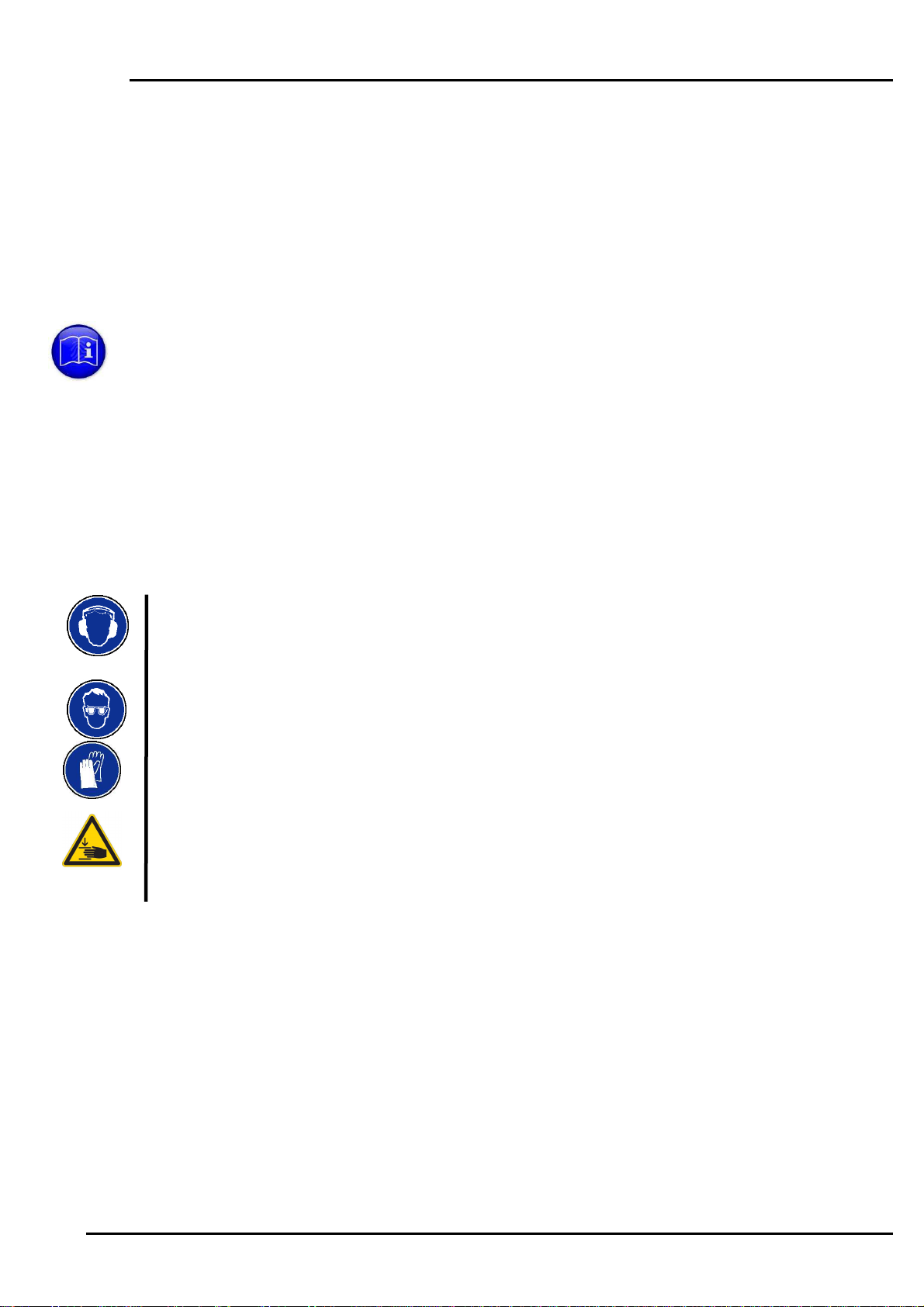
Warnings
The user should take all necessary precautions and safety measures required by law or by
customs in its operating environment, such as protection devices, warning signs, etc. It is
indispensable to have read and understood this manual and to inform all potential operators
about the safety aspects and hazards. It is vitally important that the person responsible for
safety approves the intended working modes. This manual also gives valuable information
for the optimum use of the machine.
Installation
•Check that the machine has been installed by a competent person, according to the
instructions of installation of this manual.
•Check that hanging components, booster, balancer, suspension, are properly
secured.
•Check that the suspension cable is always vertical and remains vertical for all
clinching spots.
•Check that the work head and the booster are properly fixed to their support
according to the installation instructions.
•Check that the fixation screws are present and fully tighten.
Connection
•Never connect the machine if it is not completely assembled, and fully in its working
position.
•Check the connectors, make sure that they fit to each other and free from any dust
or dirt.
•Never use air pressures above 6 bar.
•Check the conditions of all hoses and connectors. Do not use damaged elements.
Standard safety means
•Always wear safety glasses and make sure that all people close to a machine, as
soon as it is connected to the pressure line, do the same.
•Always use protective gloves when operating the machine.
•Always use hearing protector when operating the machine (noise level up to 80 dB).
•Always wear safety shoes when operating the machine
ATTEXOR Clinch Systems SA User manual
Copyright © 2010 by Bollhoff Attexor S.A. Page 7
Specific safety means
•Check that all safety protections such as fences, sliding covers, dual hand trigger as
described in the approved installation documents are all installed.
Transport
•Carry the equipment in the original or an adapted packaging to protect it from shock
•Fix the package to avoid any displacement.
Machine operation
•Check that the sheet metal to be joined held against the non moving tool side of the
machine.
•Make sure that the tooling motion is always perpendicular to the sheet metal of the
work zone, at every spot of the assembly.
•Check that the tooling motion is always reaching the exact spot location without risk
of being deviated by some protruding element.
•The normal use of the machine is operator standing up around the machine and
away from the danger zone
•Never put fingers, hand or any other body’s part in the tooling area.
•Keep fingers away from the clinching system, i.e. punch and die area, as long as the
machine is connected to the compressed air line or when residual pressure may
remain in the circuit.
•Check that the work piece to be joined is never in contact with the machine body
(notably the C’frame, the fixed and the moving jaws) during the process, other than
the positioning fixture (if any), the tooling and the stripper.
•Check that there is always sufficient room around the work piece for preventing any
risk of squeezing the operator’s fingers, hand or other body’s part between the work
piece and any other element.
•Make sure that the work piece is stably and correctly supported for preventing any
unexpected displacement during the operation.
•Never try to assemble sheet metal outside of the range of admissible thicknesses
and qualities as indicated in the table for tool selection guidelines.
•Avoid hardened steel, spring steel as well as other brittle material qualities as they
may break in a violent manner.
•Never make a second joint in the same location as a previous joint.
•Never make a joint if the punch and the die are not covering 100% the sheet metal
surface on both sides. In case of more than two sheet metal layers, make sure that
the internal layers are also covering 100% of the joint area.

ATTEXOR Clinch Systems SA User manual
Copyright © 2010 by Bollhoff Attexor S.A. Page 8
•In case a tool remains stuck in the sheet metal, never attempt to get it out by tilting or
rotating as the stripper may remain under load. Keep hands away from the tools and
the work piece, disconnect the equipment from air line and any electricity connection,
and make sure that no pressure remains in the equipment. Refer to the manual.
•In case of using the machine without trigger protection, it can turn on unexpectedly
•Hold the machine properly and be prepared to react to normal or unexpected
movements. Have both hands available. Maintain a stable posture.
Tool change and selection
•Always disconnect the machine from the compressed air line and make sure that
no residual pressure remains in the circuit by pressing the trigger/pedal before
any disassembly or service intervention on the machine.
•Never mount non-compatible punch-die units, or tools having different
eccentricities, or tools with incorrect lengths, or tools which have not been
expressively specified.
•Never put the machine under pressure without having made sure that the tooling
and the machine are set according to the prescribed setting (see instructions, H
value setting).
•Never operate the machine without the tool fixing pins, or without tightening the
tool fixing screws.
Machine integrity
•Never disassemble the hydraulic / pneumatic piston without appropriate tooling
as it is constantly loaded by a strong return spring.
•Never fill the oil reservoir beyond the maximum level.
•Never attempt to block the reservoir plug, as the latter must be free to escape in
case of over pressure.
•Check regularly the condition of the pneumatic and hydraulic hoses, couplings,
balancer cable, suspension hooks.
•Never disassemble protection material against noise (exhaust valves silencers)
disconnect the equipment from air line and any electricity connection, and make
sure that no pressure remains in the equipment.
•If the machine has been deteriorated after a fall or misuse, security functions may
be compromised. Stop using the machine and return it for repair to your
distributor or directly to Bollhoff Attexor.
•Machines should be checked periodically to ensure that the ratings and markings
are legibly marked on the machine. Contact your distributor or Bollhoff Attexor for
replacement labels, if needed.

ATTEXOR Clinch Systems SA User manual
Copyright © 2010 by Bollhoff Attexor S.A. Page 9
Note that any tampering with or modification of factory set limitations, including but
not limited to stroke length, tool kit opening, piston speed, operating pressure, etc.
will be made at the intervening person’s sole responsibility and that any such action
will discharge Bollhoff Attexor from all product liability claims and make Bollhoff
Attexor's warranty null and void. Such an intervention also nullifies the CE-mark and
Declaration of Conformity for machines originally delivered with such documents.

ATTEXOR Clinch Systems SA User manual
Copyright © 2010 by Bollhoff Attexor S.A. Page 10
Technical specifications
RIVCLINCH®0201 FS
Workhead weight, including handle 1.7
kg 3.75
lb
Total machine weight, including booster 10.0
kg 22
lb
Recommended air pressure 5 to 6
bar 72-87
psi
Max. authorized air pressure 6
bar 87
psi
Min. working air pressure 4
bar 58
psi
Air consumption per joint 4
NL
Hydraulic pressure at 6 bar air pressure 360
bar 5’250
Psi
Clinching force at 6 bar air pressure 25
kN 5.6
klb
Cycle time 0.5-0.8
s
Max. sheet metal thickness,
mild steel, total
2.5
mm
0.10''
Max. sheet metal thickness,
Stainless steel, total
1.8
mm
0.07”
Max. sheet metal thickness,
aluminium, total
3.0
mm
0.12”
Total oil volume, approx. 0.05
l
Recommended oil quality,
hydraulic circuit
ISO
VG 32
Noise level with booster 90
dB
Ref. Fig. 1
Suspension, workhead and booster (pressure intensifier).
Optional equipment:
Air preparation unit No 1, ½'', with filter, without lubricator
Tool kits: various combinations of dies and punches of type SR403 and ST332
Rotator (rotating suspension )
Balancer
For further information, consult the spare parts list.
ATTEXOR Clinch Systems SA User manual
Copyright © 2010 by Bollhoff Attexor S.A. Page 11
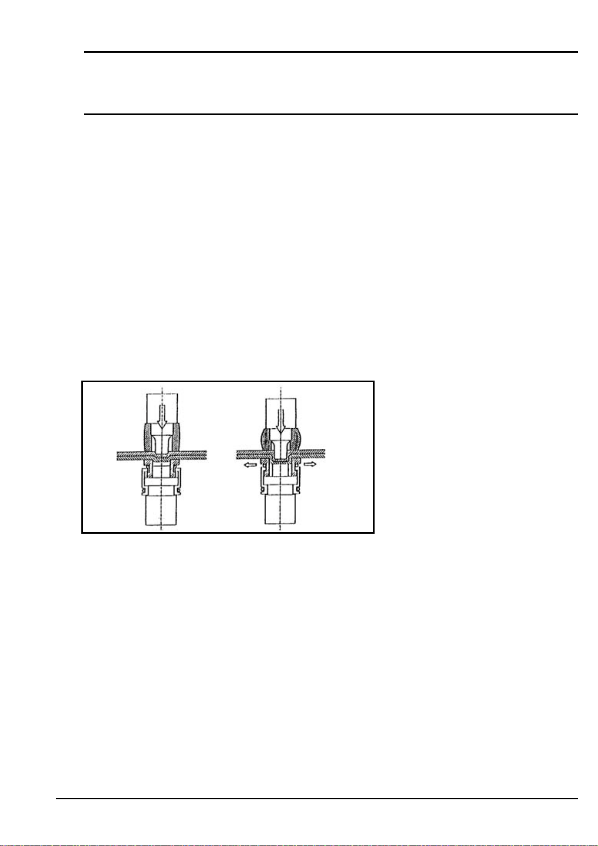
Functional description
Single-stroke clinching, opening die
The clinching method used by this RIVCLINCH
®
machine is based on a single-stroke
method, patented or patents pending world-wide by Bollhoff Attexor S.A.
1. In the first part of the process, the punch will deform the overlapping sheet
material plastically inside a die cavity. The wall of the die, typically split in two,
three or four parts, remains closed.
2. When the lower material sheet reaches the anvil, i.e. the bottom of the die cavity,
the material will flow laterally and take a mushroom shape. In this phase the die
parts will be pushed outwards, sliding on a base. After the punch has been pulled
back and the die disengaged, the die walls will close again, pulled together by a
spring.
The result is a high-quality joint in terms of shape, strength and reproducibility.
A later section will explain how the cycle described above may be optimized.
Numbers in parenthesis () in the text refer to Figs. 2

ATTEXOR Clinch Systems SA User manual
Copyright © 2010 by Bollhoff Attexor S.A. Page 12
Clinching system, end-of-stroke control
Ref. Fig. 2
The force required for a clinching is furnished by a hydraulic piston, fitted in the jaw (A1).
The hydraulic pressure is generated by an oil/air pressure intensifier, booster (C1). Ref. fig.
10, with a compression ratio of 60:1.
The trig and the duration of the cycle are controlled by the trigger (B1) which activates the
main pneumatic valve under the booster cover (C1).
The activation of the booster is only possible by a pneumatic signal given to it.
If this equipment is integrated in an automatic line, the emergency stop of the line must stop
this equipment by switching off the power source.
The clinching process is governed by the end-of-stroke position of the piston, which
determines the final position of the punch and the joint parameter St. This means that the
squeezing of the clinch joint is stable, independent on the pressure set on the regulator
(E2), provided that the set pressure is superior to the minimum required pressure for getting
the joint done. The internal end stop (A8) of the piston can be adjusted and serves not only
as a protection of the tool kit in case of activation without material, but mainly for setting the
optimal joint parameters in regard to the sheet metal to be joined and the selected tool kit.
Refer to chapter “Tooling selection and joint optimization” and Fig. 7 for instructions
about adjusting the end stop.

ATTEXOR Clinch Systems SA User manual
Copyright © 2010 by Bollhoff Attexor S.A. Page 13
Installation, Connections
Fixing, suspension
Ref. Fig. 2, Fig. 8
The normal use of the machine is hand operated, suspended by means of a rotator (A10),
and hooked to a balancer, delivered as an option. The following precautions must be
observed:
•Select a hooking position for the booster (C1) which is at least 0.5 m above the
highest working position of the work head and suspend it by the ring (C7).
•Verify that the suspension points of your installation are sufficiently strong, and
check that the eventual supporting structure is able to carry the weight of all the
attached equipments. Verify the total weight of your equipment. Usually the total
machine weight may be as high as 15 kg, including the booster and the balancer.
Notice: Take into account that the booster operation may produce vibrations in the
installation. The booster can be attached to the suspension using a spring in order
to reduce vibration.
•Check that all the suspended equipment (booster, balancer) is secured by an
additional safety cable. Contact your distributor in case of any doubt.
•Booster safety cable must be passed through holes provided therefore on the top
plate, must be attached to an independent suspension of the normal attachment
of the booster. It must provide a race fall of 100mm. The cable clamp must be
blocked on two sections of cable doubled. They must be tightened after a first test
suspension. Ref. Fig.8.
•Balancer safety cable: refer to the manual delivered with the balancer.
•Suspend the work head by the ring (A10) or preferably by the rotator delivered as
option situated between the handle and the jaw to the hook of the balancer, and
observe the instruction manual of the balancer unit.
•During all the above preparation, check that the air and oil hoses connected to the
handgrip (B2) are always free of tension bending, which may occur in case of
excessive rotation of the work head.
•Min bending radius of the flexible hydraulic hose = 100mm (4")
•Installing the booster and the workhead in a place where the lighting is at least
300 lux so as to check the oil level and to work in good conditions.

ATTEXOR Clinch Systems SA User manual
Copyright © 2010 by Bollhoff Attexor S.A. Page 14
Connection
Verify that the air supply line has an inner diameter of at least 13 mm (1/2”) for booster
S16-20-40/60 and 19mm (3/4") for booster S80-120/60, (standard coupling threads 1/2"
and 3/4" gas) and that the flow rate is sufficient. A weak flow rate will prolong the cycle time.
Under normal operating condition with about 20 clinches per minute, a compressed air line
and a compressor capable of supplying at least 120 l/min. at atmospheric pressure, is
necessary.
Connect to an air preparation unit (E2), including filter, pressure regulator and manometer.
Such units are available as options
N.B. The air preparation unit is mandatory, and must be installed prior to connect the
machine.
Check that all connectors and air tubes upstream of the filter are clean and free from dust,
water, rust and other alien particles.
Oiling the compressed air is not mandatory, but can be used for increased life of the work
head / booster air seals and air cylinder. When a lubricator is installed, it is vitally important
to avoid any excess of oil. Too much oil may cause malfunctioning in the valves and the
pneumatic control units, and may be risk for the health in case of inappropriate ventilation.
Close the oil adjustment. After starting the machine, set progressively the oil flow to a
maximum of 1.5 drops per 100 joints, equivalent to 2-3 drops per m³ of air. It is necessary
to comply with the existing regulations related the risk of oil pollution, which prevail to the
any of the above non indications
The flexible hose (E4) of the machine should be fitted with a rapid coupling (E5) without
check valve in the coupling (E5), so that the disconnection of the coupling assures a
complete and immediate bleeding of any air pressure in the booster flexible hose. As an
alternative the valve (E1) must be fitted with a bleeding valve, allowing the booster to be
fully depressurized. This is indispensable for maintenance or disassembly operation, which
must be made exclusively once the booster is full depressurized. In addition, the quick
coupling serves as a swivel allowing the machine to be rotated without limitation.
Never use an air pressure above 6.0 bar.
Verify that the clinching head is free to move and fully unobstructed. Make sure that nobody
comes close with their hands before connecting the air supply hose (E1).
Set the pressure to between 5 and 6 bar at the exit of the air preparation unit (E2). This
value should be at least equal to the clinching pressure, see below, and under no
circumstances above 6 bar (87 psi).
As a rule, the working pressure should be adjusted 0.5 bar above the minimum required
pressure for obtaining the correct joint, to be determined by testing.

ATTEXOR Clinch Systems SA User manual
Copyright © 2010 by Bollhoff Attexor S.A. Page 15
Start-up
Settings for start-up of the clinching system
Check if your machine has been pre-set in the factory for your particular application. (See
complement to user’s manual, if any)
In case the machine has not been adjusted from the factory, (or the setting has been lost),
remove the tooling (die and punch, see chapter "Replacing wear parts") and check the
reference value H as per the next chapter, “Tooling selection and joint optimization, setting
the reference value”. H must be from factory set at H=29.0 mm. If not, refer to next chapter
for re-setting the H value.
Select the tool corresponding to the sheet metal to be tested from the tables from chapter,
“Tooling selection and joint optimization.
Warning: the start-up should not be done if the H value or the tool kit is not set according
to the above instruction. In such a case, proceed with chapter "Tooling selection and joint
optimization".
Take a sample composed of two flat sheets, hold it against the die side and keep hands off
the clinching zone. Make sure that the sample is held flat against the die and
perpendicularly to the punch axis.
Press the trigger without releasing it until the total cycle has been completed. Wait until the
pressure reached the selected pressure by watching the manometer on the regulator (E2).
Then release the trigger. Wait until the punch retracted before removing the test piece.
If the pressure rises very slowly making the cycle too long, > 1 s, the air supply lines and
connectors should be checked.
Check the joint. Measure the “St” value. If needed to be modified, proceed according to the
next chapter “Tooling selection and joint optimization” and re-do the test until the correct
value of “St” is obtained.
Test the strength of the joint using a pair of jaws (never attempt to separate clinched sheet
metal with naked hands).
In order to avoid excessive tool wear, the following precautions should be respected:
•Do not remove the sheets from the die, pulling laterally as that may damage the
moving parts
•Do not attempt clinching on surfaces that are not flat or where clinching has
already been made
ATTEXOR Clinch Systems SA User manual
Copyright © 2010 by Bollhoff Attexor S.A. Page 16
•Do not tilt the sheets when the punch has penetrated. Should the sheets get
stuck, depressurize the machine. Then liberate the sheet by pulling in the axial
direction of the punch.
•Do not tilt the work head for disengaging the tooling. Always make sure that the
die blades are never forced
•Never try to assemble sheets of other material or thickness than recommended in
the tables from chapter, “Tooling selection and joint optimization
Read carefully the WARNINGS at the beginning of the manual, prior to any operation or
testing.
Using of the clinching machine
The procedure to make a clinching point is the following:
•Put together sheets of metal.
•Approach the machine in order to have flanges between the punch and the die.
•Put the fixed tool in contact with the flange.
•Be careful that the tooling is perpendicular with the sheet & that there is nothing
between layers, particularly operator's fingers.
•Press the clinching trigger (B1) without releasing until the total cycle has been
completed.
•When the cycle is finished, release the trigger.
When there are several clinching points on the same flange, be careful that there are
enough distance between points in order not to touch other points during the clinching
cycle.

ATTEXOR Clinch Systems SA User manual
Copyright © 2010 by Bollhoff Attexor S.A. Page 17
Care and Maintenance
Daily maintenance
•Check the oil level on the gauge on the reservoir (C2). Fill up if necessary. Never
go beyond the max mark.
•Check the oil level in the air preparation unit and fill up if necessary. Only use
sufficiently light oil meeting the Technical specifications.
•Check the air filter (E2). Bleed and clean regularly the water separator.
•Clean punch (A3), die and anvil (A5) with compressed air.
•Check the tooling: the die blades must be hold in contact to the anvil by the
spring. The punch top must be free from cracks or chipping.
Re-oil the tooling after cleaning. Never taking any action on the booster without having
made sure that the machine is disconnected from the line and that the air hoses eventually
still connected are free from any remaining pressure
•
Always use protective glasses when cleaning with compressed air
Weekly maintenance
This intervention should be made weekly or every 50 service hours, in case of multi-shift
operation.
Ref. Fig. 2
•Remove the punch cover (A4) for cleaning and oiling the punch head, without
removing the punch
•Clean the die-anvil (A5) with compressed air and re-oil
•Check that there are no leaks in the air connections. A leak in the logic circuit may
disturb the correct working of the machine
•Check the hydraulic connections. Do not tighten excessively the connection in
aluminum between the booster (C1) and the hydraulic hose. Maximum torque for
this connection is 20 Nm

ATTEXOR Clinch Systems SA User manual
Copyright © 2010 by Bollhoff Attexor S.A. Page 18
•Ensure that no mobile part rubs against pneumatic or hydraulic tubes and that the
latter are well in place
Maximum oil pressure may reach 400 bar. It is therefore mandatory to use only original
spare parts and to look after them attentively.
Never taking any action on the booster without having made sure that the machine is
disconnected from the line and that the air hoses eventually still connected are free from
any remaining pressure
Always use protective glasses when cleaning with compressed air
Oil change
Ref. Figs. 2 and 3
Change the oil after the first 20,000 joints and then after each 100,000 joints according to
the following procedure:
•Disconnect the supply line (E1) of compressed air, or close and bleed the valve
(E2)
•Activate the clinching process to ensure that the system is no longer under
pressure
•Do not remove the plug (C3) from the oil reservoir straight away
•Place a flat recipient under the workhead
•Turn the workhead with the plug (A10) downward. Unscrew the plug (A10)
•Remove the plug (C3)
•Fill up the reservoir (C2) directly with new oil, using an oil can, letting the oil flow
through the opening (A10)
•Let the oil run, while adding as much as needed as to avoid air bubbles to enter
Make sure that oil is added without interruption from the top, otherwise air will be introduced
in the circuit.
•Tighten the plug (C3) when the new and clean oil runs into the recipient
•Put back rapidly the plug (A10) and tighten it
•Check the level (C2) and fill up if needed
The machine is now ready for operating and the supply line (E1) may be connected again.

ATTEXOR Clinch Systems SA User manual
Copyright © 2010 by Bollhoff Attexor S.A. Page 19
Procedure for bleeding air from the hydraulic circuit
Ref. Fig. 4
When air has entered into the hydraulic system, it may be detected by a metallic impact
noise in the booster, as its piston hits the end-of-stroke, which may cause damages. The
clinching force diminishes more or less and the machine does no longer work correctly.
This is a particularly important point to watch for at start-up as air may have entered during
the transport.
In case of transportation with booster being moved upside down, there may be no external
air introduced in the oil circuit, but simply the air contained above the oil level in the
reservoir may have been moving inside of the oil circuit. In such a case the oil level is above
the maximum line of the reservoir, and the excess of oil should not be removed.
In most cases, the air bubbles may rise by themselves when the clinching action is
activated several times in rapid succession. For this operation the regulator (E2) should be
set to 3-4 bar in order to minimize the risk of damage. Stop this operation in case a metallic
sound is heard.
Fill up oil as the level falls during this operation, taking care to put back the plug (C3) each
time.
If these measures turn out to be insufficient, or if the metallic contact can not be avoided,
the oil system should be completely drained, like for changing oil, but without successive
filling.
•Remove the plug (C3)
•Wait 2 or 3 minutes for complete oil drainage, holding the flexible hose vertically
•Refill the oil through the plug (A10), using an oil can and pressing the tip of the
can into the hole of the plug (A10). This procedure guarantees the fill-up and all
air in the system will be pushed upwards
•Put back the plug (C3) once the oil level has reached the maximum line
•Put back the plug (A10) rapidly and tighten it
Check that the plug (C3) is well in place, that the oil level does not go beyond the max mark
(C2) and the plug (A10) is well tightened and fitted with its seal. Not following these
instructions may lead to disagreeable oil squirts.

ATTEXOR Clinch Systems SA User manual
Copyright © 2010 by Bollhoff Attexor S.A. Page 20
Replacing wear parts
Replacing the die-anvil set
Ref. Fig. 5, Fig.9
•Release the pressure from the system by disconnecting the inlet air hose (E1) and
by activating the clinching action to make sure that the pressure has fallen
•Remove the pin (A17) using the pin remover (A22) and a small hammer
•Pull out the anvil (A5). N.B. if the punch is still in place, it may be necessary to
remove the stripper first, as described on the section "replacing the punch-stripper
set"
•A new die and anvil is installed by following the above steps in the reverse order,
observing the right orientation of the recess on the die set
•Make sure that the anvil and the moving parts are clean and free from dirt and
that the new die has exactly the parameters required for the intended task
•Install a new die, press it down fully to put it in place
•Re-install the pin (A17) by placing it on the special recess on the tip of the pin
remover (A22). Push it with a small hammer without forcing, until the pin is fully in
place.
Do not force the die or push it sideways during the disassembly
Die ST assembly
Ref. Fig. 9
In case of replacing the die blades, check the orientation of the blades according to
Fig. 9. A wrong positioning (upside down) may significantly affect the point quality
and the lifetime of the die.
Table of contents


