bon BQM-170LS User manual

-- 1 --
OPERATING INSTRUCTIONS
Integrated 4chanel Quad View
Multi format LCD Monitor
Model : BQM-170LS(17”)
BQM-240LS(24”)

-- 2 --
IMPORTANT SAFETY INSTRUCTIONS
1. Read all of these instructions.
2. Save these instructions for later use.
3. All warnings on the product and in the operating instructions should be adhered to.
4. Unplug this appliance system from the wall outlet before cleaning. Do not use liquid cleaners or
aerosol cleaners. Use a damp cloth for cleaning.
5. Do not use attachments not recommended by the appliance manufacturer as they may cause
hazards.
6. Do not use this appliance near water “ for example, near a bathtub, washbowl, kitchen sink, or
laundry tub, in a wet basement, or near a swimming pool, etc.
7. Do not place this appliance on an unstable cart, stand, or table.
The appliance may fall, causing serious injury to a child or adult, and
serious damage to the appliance.
Use only with a cart or stand recommended by the manufacturer, or
sold with the appliance.
Wall or shelf mounting should follow the manufacturer instructions, and
should use a mounting kit approved by the manufacturer.
An appliance and cart combination should be moved with care. Quick
stops, excessive force, and uneven surfaces may cause the appliance
and cart combination to overturn.
PORTABLE CART WARNING
(symbol provided by RETAC)
8. Slots and openings in the cabinet and the back or bottom are provided for ventilation, and to insure
reliable operation of the appliance and to protect it from overheating, these openings must not be
blocked or covered.
The openings should never be blocked by placing the appliance on a bed, sofa, rug, or other similar
surface.
This appliance should not be placed in a built-in installation such as a bookcase unless proper
ventilation is provided.
9. This appliance should be operated only from the type of power source indicated on the marking label.
If you are not sure of the type of power supplied to your home, consult your dealer or local power
company. For appliance designed to operate from battery power, refer to the operating instructions.
10. This appliance system is equipped with a 3-wire grounding type plug (a plug having a third
(grounding) pin).
This plug will only fit into a grounding-type power outlet. This is a safety feature.
If you are unable to insert the plug into the outlet, contact your electrician to replace obsolete outlet.
Do not defeat the safety purpose of the grounding plug.
11. For added protection for this product during a lightning storm, or when it is left unattended and
unused for long periods of time, unplug it from the wall outlet and disconnect the antenna or cable
system.
This will prevent damage to the product due to lightning and power-line surges.
12. Do not allow anything to rest on the power cord.
Do not locate this appliance where the cord will be abused by persons walking on it.
13. Follow all warnings and instructions marked on the appliance.
14. Do not overload wall outlets and extension cords as this can result in fire or electric shock.
15. Never push objects of any kind into this appliance through cabinet slots as they may touch
dangerous voltage points or short out parts that could result in a fire or electric shock.
Never spill liquid of any kind on the appliance.
16. Do not attempt to service this appliance yourself as opening or removing covers may touch
dangerous voltage or other hazards. Refer all servicing to qualified service personnel.

-- 3 --
17. Unplug this appliance from the wall outlet and refer servicing to qualified service personnel under
the following conditions:
a. When the power cord or plug is damaged or frayed.
b. If liquid has been spilled into the appliance.
c. If the appliance has been exposed to rain or water.
d. If the appliance does not operate normally by following the operating instructions.
Adjust only those controls that are covered by the operating instructions as improper adjustment of other
controls may result in damage and will often require extensive work by a qualified
technician to restore the appliance to normal operation.
e. If the appliance has been dropped or the cabinet has been damaged.
f . When the appliance exhibits a distinct change in performance this indicates a need for service.
18. When replacement parts are required, be sure the service technician has used replacement parts
specified by the manufacturer that have the same characteristics as the original part. Unauthorized
substitutions may result in fire, electric shock, or other hazards.
19. Upon completion of any service or repairs to this appliance, ask the service technician to perform
routine safety checks to determine that the appliance is in safe operating condition.
FCC NOTICE
This device complies with Part 15 of FCC Rules.
Operation is subject to the following two conditions :
(1)This device may not cause harmful interference, and (2) this device must accept any interference received,
including interference that may cause undesired operation.
To assure continued compliance, follow the attached installation instruction and do not make any unauthorized
modifications.
Note:
This equipment has been tested and found to comply with the limits for a class B digital device, pursuant to Part 15 of
the FCC Rules. These limits are designed to provide reasonable protection against harmful interference in a
residential installation. This equipment generates, uses, and can radiate radio frequency energy, and if not installed
and used in accordance with the instructions, may cause harmful interference to radio communications. However,
there is no guarantee that interference will not occur in a particular installation. If this equipment does cause harmful
interference to radio or television reception, which can be determined by turning the equipment off and on, the user is
encouraged to try to correct the interference by one of the following measures:
-Reorient or relocate the receiving antenna.
-Increase the separation between the equipment and receiver.
-Connect the equipment into an outlet on a circuit different from that to which the receiver is connected.
-Consult the dealer or an experienced radio/TV technician for help.
The user may find the booklet “Something About Interference” available from FCC local regional offices helpful.
Warning :
To assure continued FCC emission limit compliance, the user must use only shielded interface cables when
connecting to host computer or peripheral devices. Also, any unauthorized changes or modifications to this equipment
could void the user’s authority to operate this device.

-- 4 --
SAFETY PRECAUTIONS
CAUTION
RISK OF ELECTRIC SHOCK
DO NOT OPEN
CAUTION: TO REDUCE THE ELECTRICK SHOCK.
DO NOT REMOVE COVER (OR BACK).
NO USER SERVICEABLE PARTS INSIDE.
REFER SERVICING TO QUALIFIED SERVICE PERSONNEL
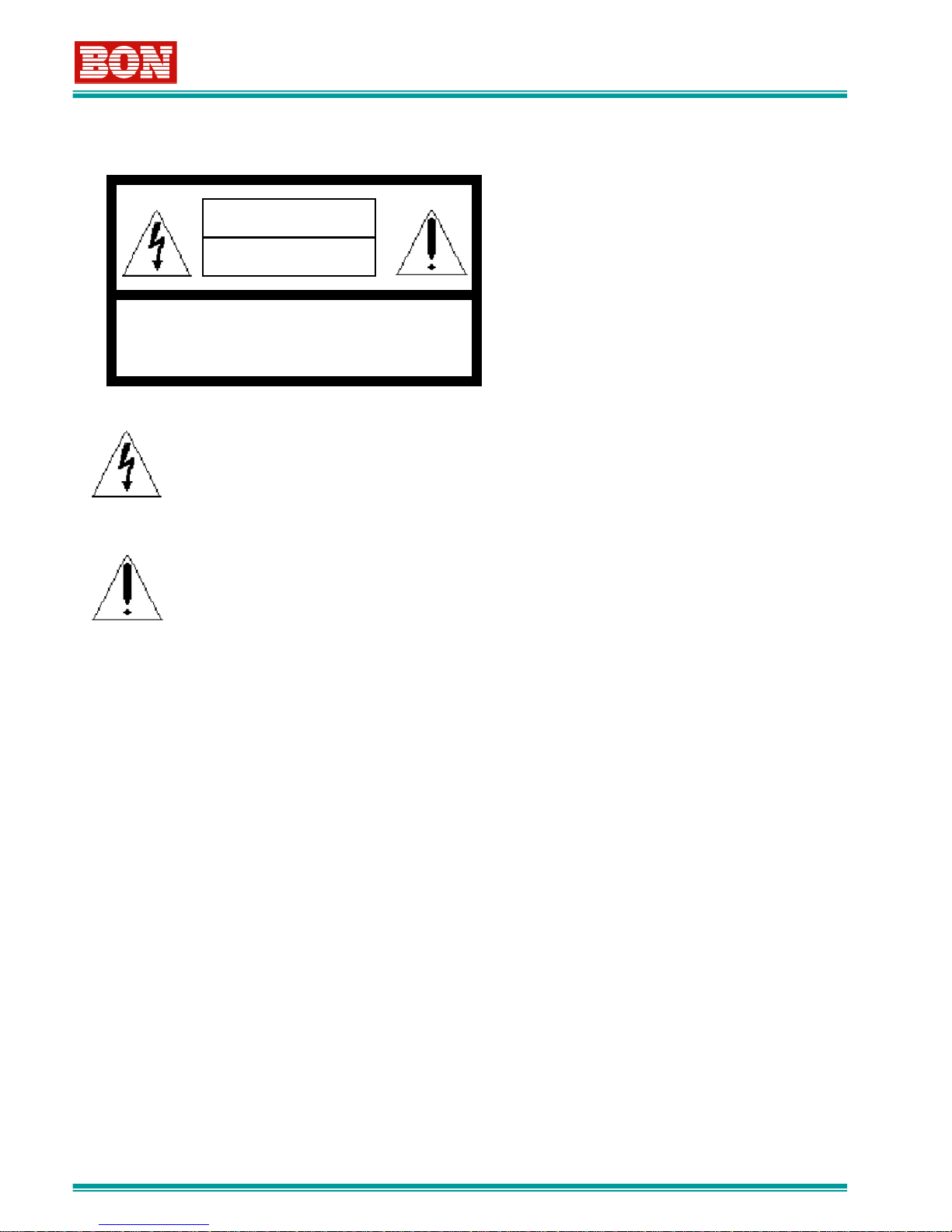
The lightening flash with arrowhead symbol,
within an equilateral triangle, is intended to
alert the user to the presence of uninsulated
“dangerous voltage” within the product’s
enclosure that may be of sufficient magnitude
to constitute a risk of electric shock to
persons.
The exclamation point within an equilateral
triangle is intended to alert the user to the
presence of important operating and
maintenance (servicing) instructions in the
literature accompanying the appliance.
WARNING :
-TO REDUCE THE RISK OF FIRE OR SHOCK
HAZARD, DO NOT EXPOSE THIS EQUIPMENT
TO RAIN OR MOISTURE.
-TO REDUCE THE RISK OF FIRE OR SHOCK
HAZARD, KEEP THIS EQUIPMENT AWAY FROM
ALL LIQUIDS. USE AND STORE ONLY IN
LOCATIONS WHICH ARE NOT EXPOSED TO
THE RISK OF DRIPPING OR SPLASHING
LIQUIDS, AND DO NOT PLACE ANY LIQUID
CONTAINERS ON TOP OF THE EQUIPMENT.
CAUTION :
In order to maintain adequate ventilation, do not
install or place this unit in a bookcase, built-in
cabinet or any other confined space. To prevent
risk of electric shock or fire hazard due to
overheating, ensure that curtains and any other
materials do not obstruct the ventilation.
CAUTION :
TO REDUCE THE RISK OF FIRE OR SHOCK
HAZARD AND ANNOYING INTERFERENCE, USE
THE RECOMMENDED ACCESSORIES ONLY.
CAUTION :
This apparatus can be operated at a voltage in the
range of 100-240 V AC.
Voltage other than 120V are not intended for U.S.A
and Canada.
CAUTION :
Operation at a voltage other than 120V AC may
require the use of a different AC plug. Please
contact either a local service center for assistance
in selecting an alternate AC plug.
Notice (U.S.A. only) :
This product has a fluorescent lamp that contains a
small amount of mercury. It also contains lead in
some components. Disposal of these materials
may be regulated in your community due to
environmental considerations. For disposal or
recycling information please contact your local
authorities, or the Electronics Industries Alliance:
<http://www.eiae.org.>
THIS EQUIPEMNT MUST BE GROUNDED
To ensure safe operation, the three-pin plug must be
inserted only into a standard three-pin power outlet
which is effectively grounded through normal household
wiring. Extension cords used with the equipment must
have three cores and be correctly wired to provide
connection to the ground. Wrongly wired extension
cords are a major cause of fatalities. The fact that the
equipment operates satisfactorily does not imply that
the power outlet is grounded or that the installation is
completely safe.
For your safety, if you are in any doubt about the
effective grounding of the power outlet, please consult a
qualified electrician.
CAUTION:
THE AC RECEPTACLE (MAINS SOCKET OUTLET)
SHALL BE INSTALLED NEAR THE EQUIPMENT AND
SHALL BE EASILY ACCESSIBLE.
TO COMPLETELY DISCONNECT THIS EQUIPMENT
FROM THE AC MAINS, DISCONNECT THE POWER
CORD PLUG FROM THE AC RECEPTACLE.

-- 5 --
•Resolution 1920 X 1080
•Aspect ratio 16:9
•Contrast 600:1
•Viewing Angle: 160 ˚
•Input :
SDI(4EA,BNC), Analog(3EA,BNC),
Y/C, DVI-I, HDMI, LTC
•Output :
SDI(4EA,BNC)
•Power : AC100-230V
•Resolution 1920 X 1200
•Aspect ratio 16:10
•Contrast 700:1
•Viewing Angle : 178 ˚
BQM-170LS
( 17 Inch HD LCD Monitor )
BQM-240LS
( 24 Inch HD LCD Monitor )
BQM Series
•Input :
SDI(4EA,BNC), Analog(3EA,BNC),
Y/C, DVI-I, HDMI, LTC
•Output :
SDI(4EA,BNC)
•Power : AC100-230V

-- 6 --
Thank you for purchasing this product. Before operating this product, please
read this instructions carefully and save this manual for later use
Contents
1. Out Line •••••••••••••••••••••••••••••••••••7
2. Main Features ••••••••••••••••••••••••••••••••7
3. Controls and Functions ••••••••••••••••••••••8
3-1. Front Panel••••••••••••••••••••••••••••••••8
3-2. Rear Panel ••••••••••••••••••••••••••••••11
3-3. Tally & Audio •••••••••••••••••••••••••••••••13
3-4. Front F1,F2의Function ••••••••••••••••••••••••14
4. STATUS Display •••••••••••••••••••••••••••15
5. INPUT Select •••••••••••••••••••••••••••••••17
5-1. FULL Mode •••••••••••••••••••••••••••••17
5-2. SPLIT Mode •••••••••••••••••••••••••••••18
5-3. Display Mode(Lay Outs) •••••••••••••••••••••••••19
6. OSD Menu Control ••••••••••••••••••••••••••••••21
6-1. MENU Setup•••••••••••••••••••••••••••••21
6 - 2 . M A I N M E N U •••••••••••••••••••22
6-3. VIDEO Setup •••••••••••••••••••••••••24
6-3-1. VGA COLOR Setup •••••••••••••••••••••••25
6-3-2. VGA DISPLAY Setup••••••••••••••••••••••••25
6-4. DISPLAY Setup •••••••••••••••••••••••••••26
6-5. COLOR Setup ••••••••••••••••••••••••••••••30
6-6. MARKER Setup••••••••••••••••••••••••••••••31
6-7. OSD Setup•••••••••••••••••••••••••••••32
6-8. SOURCE ID Setup•••••••••••••••••••••••••••••34
6-9. AUDIO Setup•••••••••••••••••••••••••••••35
6-10. GPI Setup•••••••••••••••••••••••••••••37
6-11. SYSTEM Setup ••••••••••••••••••••••••••••38
6-12. INFO Setup••••••••••••••••••••••••••••39
7. Remote Terminal Assignment •••••••••••••••••••••••40
7-1. Remote Terminal(RJ-45)Assignment •••••••••••••••••40
7-2. How to connect GPI Port(RJ-11)••••••••••••••••••40
7-3. Remote Terminal Assignment ••••••••••••••••••41
8. Program Update Port •••••••••••••••••••••42
8-1. How to connect Multi Monitors •••••••••••••••••42
9. List of Compatible Signal Formats••••••••••••••••••••43
9-1. Input Video Signals ••••••••••••••••••••••43
9-2. Computer signals (PC-RGB/DVI) ••••••••••••••••44
10. Specifications •••••••••••••••••••••••••••••••45
11. DIMENSIONS •••••••••••••••••••••••••••46
12. T r o u b l e s h o o t i n g •••••••••••••••••47
13. ( M a i n t e n a n c e ) •••••••••••••••••••47
14. Up version and Modification of Product •••••••••••••••47

-- 7 --
1. Outline
2. Functions and Features
BON HD Digital Monitor series are a Multi-Format HD Monitors
with high core technology to display various kind of digital
video input signals. It supports HD / SD-SDI, RGB, Component
and Composite signals
• High Quality Video Display with RGB 10BIT Digital Signal Process
• High Speed Response in LCD panel
• 4ch HD-SDI Signal Input
• Color Calibration (Optional Software)
• DVI & HDMI Input Mode Support
• Multiple-View Layout Mode Support (Single Mode, Split Mode 1~9)
• HD 2K Format, HD/SD-SDI Multi Format Signal Support
• HD/SD-SDI Auto Sensing/Loop Out
• Pixel to Pixel Display(17 inch Model Only)
• De-embedded Audio Output & Analog Audio Input
• Various Marker Display (Safety Area, Aspect)
• H/V Delay, Blue/Mono (Precision Monitoring)
• Over Scan/Zero Scan/Under Scan/Zoom
• Anamorphic Mode Display
• Remote GPI Control (RJ-45)
• Serial Control Port (Update & Control), (RJ-11)
• Built-In Speakers & Ear Phone Jack (Option)
• Time Code Display
• Vector Scope Display (Except PC-RGB, DVI, HDMI)
• Video Waveform Display (Except PX-RGB, DVI, HDMI)
• Internal Pattern Signal Display
• De- embedded 1~16ch SDI/External /HDMI 2ch Audio Level Meter Display
• Caption608( Line 21/VANC/Transcoded), 708 support
• Tally Lamp
• UMD Display, Viudeo Channel ID
• User Friendly OSD Menu Setup
• Wide Viewing Angle
• Picture Adjustment(Bright, Contrast, Hue/ Phase, Chroma, Sharpness)
• Rack & VESA Mountable
Please refer to Specification Sheet for detailed Option

-- 8 --
3. Control and Functions
3.1. Front Panel
BQM-170LS,240LS(Front Push Button)
3.1. Front Panel
①STANDBY
-Power ON/OFF Button. When you power OFF, it operates after being pushed
about 1 second
②SDI, SDI2, SDI3, SDI4 INPUT SELET
-Used to select HD/SD-SDI CH1, CH2, CH3, CH4
③YPbPr, RGB(Component) INPUT SELECT
-Used to select Components Signal
-By pressing this button, it converts Input modes between YPbPr and RGB Mode
④DVI/VGA INPUT SELECT
-Used to select DVI/VGA Signal
-By pressing this button, it converts Input mode between DVI and VGA Mode
⑤HDMI INPUT SELECT
- Used to select HDMI Signal

-- 9 --
⑥CVBS1, CVBS2,CVBS3, Y/C INPUT SELECT
-Used to select Composite Signal(CVBS), Y/C(S-Video)Signal.
-By pressing this button, it converts Input modes between CVBS1,2,3 and Y/C mode
⑦FULL/SPLIT
-Used to convert Display Mode between Full Mode and Split Modes
-FULL Mode : shows 1 signal source only.
-SPLIT Mode :shows 2 or 4 signal sources together
⑧SHIFT
-Used to convert another Display mode in Split mode
-Split mode provides 10 different layouts
(For details, refer to 7. Split Mode Lay Out)
⑨FUNCTION(F1,F2)
-Carries out the item selected in the SYSTEM Menu
-You can assign desired function into each button.
⑩MENU
-Used to start OSD MENU. Please refer to category 6
⑪BLUE/GRAY(▲)
1) When this button is pushed, Display Color is shown only with B(blue)signal or it shows
only Luminance without color. Each time being pressed, it converts Blue-> Gray->
Color
2) When OSD Menu is ON, it works as UP(▲) button
3) Please note : In SPLIT MODE, this function applies all split window simultaneously
⑫Ch, SELECT
-Used to select desired channel in SPLIT Mode.

-- 10 --
⑬W-FORM/VECTOR
-This function is only activated in Full Mode ONLY(Not SPLIT Mode)
-When this button being pushed, it shows waveform or vector scope for corresponding input
-By being pushed, it converts each mode between waveform and vectorscope
-Please note : this function does not work in DVI/HDMI/VGA(PC-RGB)Mode
⑭ENTER/MARKER
1) When OSD Menu is ON, this button is used as Enter Key.
This button is used to save the selected item and to go to next step. For detailed information,
Please refer to category 6. OSD Menu Control
2) When OSD Menu is not ON, it works as Marker button
⑮SCAN/ZOOM(▼)
1) Used to convert Zero Scan, Under Scan or Over Scan , Zoom Scan mode
2) When OSD Menu is ON, it works as Down(▼) Button
⑯ADJ VOLUME
-When button selected, corresponding VOLUME MENU is activated, and when selected one
more time, it become inactivated.
When this button turned into ClockWise, Volume will be increased.
When this button turned into Counter ClockWise, Volume will be decreased.
Brightness
Contrast
Chroma
Phase
Speaker Volume
Possible to control
these functions
⑰Ear-Phone Jack(Option)
-Available to listen to Speaker Signal via Ear Phone.At this moment, Internal Speaker does
not work.
-Ear Phone Volume Sound is controlled by Speaker Volume Set

-- 11 --
3.2. Rear Panel
BQM-170LS Rear panel BQM-240LS Rear panel
①REMOTE
RJ-45
②SDI 1
③SDI 2
CVBS1,2
,3 &
COMPO
NENT
⑥S-VIDEO
⑩UPDATE
⑪AUDIO
IN/OUT
⑫SDI
LOOP OUT
⑭
HDMI
④SDI 3
⑤SDI 4
⑦DVI
⑧
⑨AC IN
LTC IN
⑬
①REMOTE
RJ-45
②SDI 1
③SDI 2
CVBS1,2,3
&
COMPON
ENT
⑥S-VIDEO
⑩UPDATE
⑪AUDIO
IN/OUT
⑫SDI
LOOP OUT
⑭
HDMI
④SDI 3
⑤SDI 4
⑦DVI
⑧
⑨AC IN
LTC IN
⑬

-- 12 --
①REMOT(RJ-45 Jack)Port
-Used for external Control(Make/Trig type terminal)
-For detailed information, please refer to category8. Terminal Assignment Connection
②③④⑤ :SDI Input Port
- HD/SD-SDI Signal Input Port. SMPTE standard type. Aviailable to input SDI signal which includes
Audio Signal.
⑥Y/C(S-Video) :
-Used to input Y/C(S-Video) Signal
⑦DVI-I :
-Used to input DVI-I Digital Signal
⑧HDMI :
-Used to input HDMI Digital Signal(HDCP1.1 Support)
⑨AC INPUT Port :
-Used to supply AC(100V~230V)Power
Used only the power cord designated to ensure safety and EMC regulation of each
countries
⑩UPDATE Port(RJ-11 Jack)
-Serial Communication Port. This Port is used to modify monitor program or to control Monitor.
-For detailed information, please refer to category 7. Program Update Port
⑪AUDIO IN/OUT
-Input/Output terminal for the external Audio and Embedded Audio Signal.
-Please refer to category3-3. Audio Input/Output for detailed information
⑫SDI LOOP OUT PORT
-This is Active Loop Signal Output Terminal for each of SDI1,2,3,4
IF Monitor is Stand-by OFF, it does not work
⑬LTC IN Port (Longitudinal Time Code)
-Used to match clock source with external LTC input signal in sync in Split Mode 4
⑭Component YUV/RGB & CVBS1,2,3 Input Port
-Used to input Composite signal/ Component (YPbPr/ RGB) Signal

-- 13 --
3.3. Tally & Audio
UMD Tally
LED Tally
There are 2 different Tally types(LED, UMD). The colors are 2types(Red, Green).
Color can be selected by External Contact terminal
1) Tally
1) Audio In/Output
①Analog Audio L/R Input Terminal(3.5mm Phone Jack)
-External Input Port for Analog Input.
-The external Analog Audio Signal is available through the speaker by a Menu set
②Analogue Audio L/R Output Terminal(3.5mm Phone Jack)
-Terminal for Analog Audio Signal Out
-Available to select and out De-embedded 16CH Audio Signal or External Input signal by Menu Set.
-Audio Out Signal is not adjusted by Speaker Volume. It outputs the original inputted level.
-Please refer to 6-5. Embedded Audio Setup

-- 14 --
3.4. Function Buttons for F1, F2
Note
H/V Delay and Marker will not be supported in following input mode
-DVI/HDMI
-PC-RGB(VGA)
There are 2 push buttons located on the front panel. Function1 and Function2. You can select and
designate desired function into each button from below list
-F1 Default Value : Audio Display
-Fe Default Value : H/V Delay
◊Selectable Functions◊
•Audio LM Display
•Caption Display
•Timecode Display
•Fast Mode
•Anamorphic
•Pixel to Pixel
•Aspect
•PC Scan
•Front Button LED
•Freeze
•H/V Delay
•Audio Mute

-- 15 --
4. STATUS DISPLAY
Used to confirm the operating status. Some functions may not be supported depending
on the installed options
When Menu is activated, Information indication such as Audio Level Meter,
Timecode, Source ID is designed to be lighter in color
Time Code Display Displays selected
channel’s signal
format information
Displays Left Audio Level Meter
Ch1,3,5~15
Displays Right Audio Level Meter
Ch2,4,6~16

-- 16 --
1) Audio Level Meter Display
-Sets “ON/OFF” and “POSITION” from Audio Level Display Menu
-ON: Displays Level Meter (Left shows even ch/Right shows odd ch)
-OFF: Display Off Level Meter
█Audio Level Meter Direction Assignment : You can set either Horizontal or Vertical bar.
█Even though you set Audio Level Meter ON, if there is no incoming signal, then, it does
not show the audio level bar
2) Waveform/Vector Scope Display and Setup
-You can set ON/OFF by pressing W-FORM/VECTOR Button
-Waveform Position can be assigned by OSD Menu
█Waveform Position : Left Top/Right Bottom/Left Bottom /Right Top
█You can select Waveform among Y, Cb,Cr by OSD Menu Setup
█Vector Color is set to 75% & 100%
█Waveform & Vector scope cannot be displayed if No Signal inputted
█With the exception of SINGLE/SPLIT2,3,5,6 Mode, waveform or vector scope will not be
displayed.
3) Time Code Display
-Sets “ON/OFF” from OSD Menu
█Even though you set Time Code Display ON, if there is no incoming signal, then, it does
not show the Time Code Display
█Time Code Display is available in SDI input Mode ONLY. Depending on input Video Data
Signal’s resolution, following Line No , below 4 functions will be supported.
(LTC in HANC, VITC1 in HANC, VITC2 in HANC, DVITC)
When menu is incorrectly set, Time Code shape can be displayed, but function
may not be correctly displayed. When Time Code is not correctly displayed, please
check the setting status based on input signal.

-- 17 --
5-1. Full Mode
-Push FULL/SPLIT Button to be Full Mode.
-FULL/SPLIT KEY LED will be off in Full Mode
█SDI-1/SD-2/SDI-3/SDI-4 : Used to select HD/SD-SDI signal.
█YPbPR/RGB : Used to select Component YPbPr or Component RGB signal input.
YPbPr Signal support both SD level and HD level and monitor will auto sense signals.
By pressing this button, it converts input modes between YPbPr and RGB
█DVI/VGA :Used to select DVI or VGA(PC-RGB)
By pressing this button, it converts input modes between DVI and VGA
█HDMI : Used to select HDMI(with HDCP1.1) signal.
█CVBS1,2,3/Y/C: Used to select Composite Signal and Y/C(S-Video)
By pressing this button, it converts input modes as following :
CVBS1->CVBS2-> CVBS3->Y/C
5. INPUT SELECT
①TO CHANGE
FULL/SPLIT MODE
②TO CHANGE
LAYOUT IN SPLIT
MODE
③TO SELECT
DESIRED CHANNEL
IN SPLIT MODE

-- 18 --
█SPLIT Layout Mode Change :
In Split Mode, to change layout, press SHIFT KEY button, then, it will change layout out of 9
designated different Layout Modes. (refer to 5-3 SPLIT MODE Layout )
█Channel Selection in SPLIT Mode :
-In Split Mode, each time Ch. Select Key button being pressed, desired channel will be
selected accordingly and selected channel’s source ID character’s background color will be
BLUE and corresponding LED will be ON
5.2. SPLIT MODE
Push FULL/SPLIT Button to be SPLIT Mode.
In this mode, FULL/SPLIT Key LED will be ON
Selected Channel’s Source ID character
background color will become BLUE
In split mode, there are 9 different layouts and each layout can be
selected by pressing “SHIFT” Button. To change different layout, once
button being pressed, it may take 3~5seconds

-- 19 --
5.3. SPLIT MODE Lay Out
<SPLIT-MODE1>QUAD VIDEO <SPLIT-MODE2>Video + Measure
<SPLIT-MODE3>Video + Measure <SPLIT-MODE4>2Video + Clock
<SPLIT-MODE5>2Video + Measure <SPLIT-MODE6>2Video + Measure

-- 20 --
5.3. SPLIT MODE Lay Out
<SPLIT-MODE9>1 + 3 Video <FULL Mode>
<SPLIT-MODE7>1 + 2 Video <SPLIT-MODE8>1 + 3 Video
This manual suits for next models
1
Table of contents
Other bon Monitor manuals