bon FM-055F User manual

Multi-Format Field Monitor
FM-055F
User’s Guide

Contents
Safety Instructions.........................................................................................................3
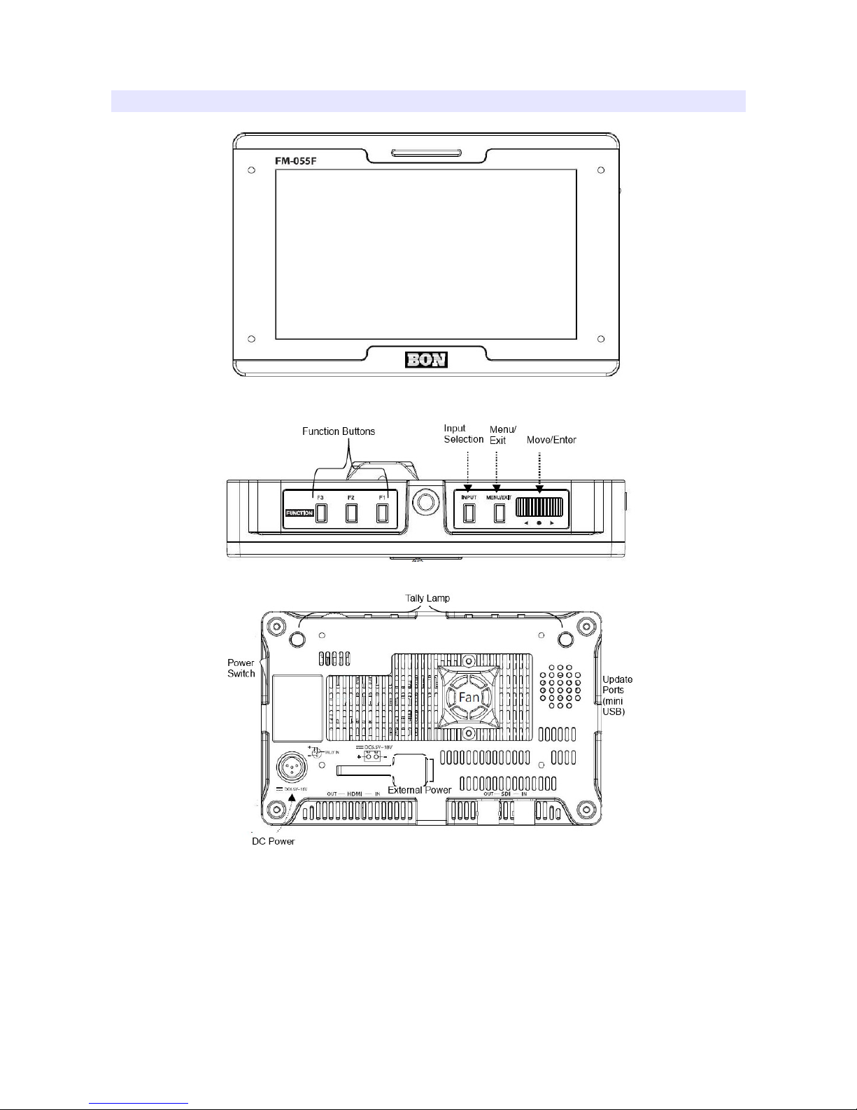
Appearance...................................................................................................................4
Buttons...........................................................................................................................5
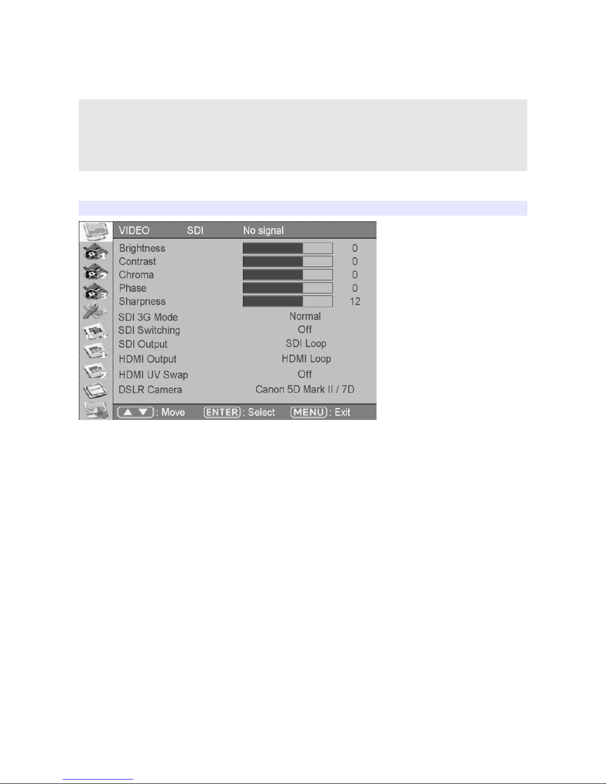
OSD Menu.........................................................................................................................6
VIDEO............................................................................................................................6
DISPLAY .....................................................................................................................9
DISPLAY 2...................................................................................................................
COLOR........................................................................................................................ 3
MARKER..................................................................................................................... 4
OSD .......................................................................................................................... 5
OSD 2.......................................................................................................................... 6
AUDIO......................................................................................................................... 8
SYSTEM......................................................................................................................20
Program Update Port (PGM).......................................................................................2
Troubleshooting...........................................................................................................22
Warranty Information...................................................................................................24
Modification of Product................................................................................................24
Caution on Menu Operation........................................................................................24
Caution for Monitor Placement....................................................................................24
2

Safety Instructions
•Rough handling of product may cause physical damage or malfunction.
•Never insert anything metallic into the monitor openings. Doing so may create the
danger of electric shock.
•To avoid electric shock, never touch the inside of the monitor. Only a qualified should
open the monitor’s case.
•Openings in the monitor cabinet are provided for ventilation. To prevent overheating,
these openings should not be blocked or covered.
•Put your monitor in a location with low humidity and a minimum of dust. Avoid places
like damp basement or dusty hallways.
•Place the monitor on a solid surface and treat it carefully. The screen is made of glass
and can be damaged if dropped or sharply hit.
•Do not attempt to remove the back cover, as you will be exposed to a shock hazard.
The back cover should only be removed by qualified service personnel.
•Unplug the monitor power before you connect external devices to the monitor.
•If your monitor does not operate normally, or if there are any unusual sounds or smells
coning from it, unplug it immediately and contact us.
•Please do not disassemble the monitor. No service will be provided in that case.
•Displaying fixed picture for a long time may cause an afterimage or dead spots. To
recover LCD pixels, display whole white picture on screen for a n hour or two and pixels
will be recovered.
•No service will be provided for user’s own color calibration.
3

Appearance
4

Buttons
Po er S itch
turns power on/off.
Menu/Exit
displays the OSD menu or exit from current menu.
Input
selects input signal.
Function 1~3
Activates/deactivates function ~3.
Audio Out
enables user monitor the audio by headphone.
USB
is used to update the firmware.
Serial
is used to update the firmware or to calibrate color.
DC Po er Port
is used to supply power to the monitor. Use up to 2V adapter or up to 8V battery.
Furthermore, tally is automatically turned on/off by tally pins.
External Po er
is used to supply power using an external battery up to 8V. Be careful on the electronic
polar direction.
5

OSD Menu
* The menu may disappear on no signal or instable signal input.
* Menu setting is saved for each input mode. So the user should make
selection on an appropriate input mode.
* If there's no picture change for long, the picture might be left
unchanged for some time.
VIDEO
Brightness
Adjust brightness.
Contrast
Adjust contrast.
Chroma (Hue)
Adjust chroma.
Phase
Adjust phase.
Sharpness
Adjust sharpness.
6

SDI S itching
Enables smooth switching on the picture if input picture source is changed quickly from
such input device as routing switcher.
SDI 3G Mode
Set this mode if the input is 3G HD SDI. SDI 3G mode support SMPTE standards listed
below:
▶A_MS1_YCbCr422_10
: 3G SDI Level-A Mapping Structure 1 YCbCr 4:2:2/10 bit
▶A_MS2_YCbCr444_10
: 3G SDI Level-A Mapping Structure 2 YCbCr 4:4:4/10 bit
▶A_MS2_RGB444_10
: 3G SDI Level-A Mapping Structure 2 RGB 4:4:4/10 bit
▶A_MS3_YCbCr444_12
: 3G SDI Level-A Mapping Structure 3 YCbCr 4:4:4/12 bit
▶A_MS3_RGB444_12
: 3G SDI Level-A Mapping Structure 3 RGB 4:4:4/12 bit
▶A_MS4_YCbCr422_12
: 3G SDI Level-A Mapping Structure 4 YCbCr 4:2:2/12 bit
▶B_MS1_YCbCr422_10
: 3G SDI Level-B Mapping Structure 1 YCbCr 4:2:2/10 bit
▶B_MS2_YCbCr444_10
: 3G SDI Level-B Mapping Structure 2 YCbCr 4:4:4/10 bit
▶B_MS2_RGB444_10
: 3G SDI Level-B Mapping Structure 2 RGB 4:4:4/10 bit
▶B_MS3_YCbCr444_12
: 3G SDI Level-B Mapping Structure 3 YCbCr 4:4:4/12 bit
▶B_MS3_RGB444_12
: 3G SDI Level-B Mapping Structure 3 RGB 4:4:4/12 bit
▶B_MS4_YCbCr422_12
: 3G SDI Level-B Mapping Structure 4 YCbCr 4:2:2/12 bit
▶B_2X_DS1_YCbCr422_10
: 3G SDI Level-B Data Stream 1 YCbCr 4:2:2/10 bit, Dual Link SMPTE-372M
▶B_2X_DS2_YCbCr422_10
: 3G SDI Level-B Data Stream 2 YCbCr 4:2:2/10 bit, Dual Link SMPTE-372M
7

Especially for G Level B signals, the format should be set manually.
Also, be aware that the format information might be lost on power down.
HDMI UV S ap
Sometimes UV signal might be opposite such input as PC RGB or such resolution as
PC’s. Turn this mode on to see correct color when the incorrect color displayed on this
kind of input.
SDI Output
Set how to use SDI Out port. Choose either SDI loop-through or HDMI-to-SDI conversion
out.
DSLR Camera
Set which DSLR camera you use for DSLR Zoom mode. DSLR Zoom mode can be set by
pressing Zoom button in the front.
8

DISPLAY 1
Aspect
Sets the aspect ratio of the screen. 6:9, 4:3, Native(Original) are selectable.
Anarmorphic
Set this mode to resize the screen to 3.56: , 2.74: , 2.59: , 2.55: , 2.40: , 2.39: , 2.35: ,
.85: , .75: , .66: , or .37: .
Waveform Display
Select waveform display mode. Choose Normal to analyze whole screen, choose Line
Select to analyze a specific line of the screen.
Waveform Line Select
Select the line when you select Line Select mode for Waveform display.
Waveform Select
Select which color signal to monitor among Y, Cb, or Cr.
Waveform Color Mode
Choose either Single or Mixed.
Waveform Intensity
Set waveform color’s intensity between 0~63.
WFM & Vector Size
Set Waveform and Vectorscope size among three kinds.
9

WFM & Vector Blend
Set transparency of Waveform and Vectorscope window between 0~6.
YCbCr
YCbCr is a digital color reproduction standard. Y is for luminance, Cb
is for blue strength, Cr is for red strength.
0

DISPLAY 2
Timecode Display
Set this mode on to display timecode from SDI signal. Select the appropriate timecode that
you wish to display among LTC (Longitudinal Time Code), VITC (Vertical Interval Time
Code), DVITC (Digital Vertical Interval Time Code).
Timecode Position
Set Top or Bottom position for timecode.
Exposure Range Check (Video Range Check)
Checks Y, C level and displays over-exposed or under-exposed area on screen. The base
value can be Y, Cb, or Cr.
Y Range Max / Min
Set Y range value for range check.
C Range Max / Min
Set C range value for range check.
Blink Color
The filled area color by range check can be either Black, Blue, Green or Red.
Blink Time
Set blinking time of the area between to 5 seconds.
Focus Assist
Turns on Focus Assist mode. This mode can be set also by pressing Focus Assist button

in front.
Focus Assist Box
Sets focus assist box size for user-interested region among small/medium/large, instead of
setting full screen focus assist.
Focus Assist Position
Adjusts focus assist box position among 9 positions from the center, top-left, top-middle,
top-right, left, center, right, bottom-left, bottom-middle, bottom-right.
Focus Assist Color
Set brush color of focus assist mode among Blue, Green, and Red.
Focus Assist Level (Sensitivity)
The sensitivity of the focus assist function can be set between 0 to 48.
False Color
Shows pictures in specific colors as its luminance level other than the original colors. Much
exposed area is filled with red while little exposed area is purple.
* 10-bit, 12-bit Dithered gradient pattern might not be displayed
clearly in this mode.
2

COLOR
Dithering
Set this mode on to display gradient more smoothly.
Auto Color Temperature
Set this mode on to adjust color temperature by temperature change. Its output might
incorrect on some harsh environment.
Color Temperature
VAR, 3200K, 5400K, 6500K, 9300K color temperatures are preset and selectable by user.
On User mode, user can adjust RGB gain and bias. Adjusting on User mode is
recommended to professional users.
3

MARKER
Marker Ratio
Select one of preset markers or user marker. To display marker, press Marker button in
front of the monitor.
Center Marker
Set preference to display center marker or not.
Safety Area 16:9
Adjust size of the safety area when marker displayed on 6:9 screen.
Safety Area 4:3
Adjust size of the safety area when marker displayed on 4:3 screen.
Marker Color
Select marker’s color among White, Red, Green, Blue, Gray and Black.
Marker Mat
Set how to display outside of the safety area. Normal, Half(Gray), Black are selectable.
Marker Thickness
Set marker thickness between to 0.
User Marker H1 / User Marker H2 / User Marker V1 / User Marker V2
Set user marker’s position. H for left, H2 for right, V for top, V2 for bottom. The positions
are saved as the selected marker name such as USER .
4

OSD 1
OSD Display Time
Set OSD menu display time. Choose 0 for infinite.
OSD Blend
Set transparency of the menu between 0 to 5.
OSD(Menu) Position
Set menu position among Left Top, Right Top, Left Bottom, Right Bottom and Center.
Internal Pattern
To test monitor display without signal, turn this mode on. Several patterns such as Color
Bars, Blue, Green, Red, White and Black are selectable.
5

OSD 2
H/V Level Meters
Displays the horizontal and vertical angle on screen.
H/V Level Position
Sets the position of level meters.
H/V Size
Sets large or small level meter size.
H/V Sensitivity
Sets the sensitivity of level change.
Flip/Level Reset
Resets the flip and angle meters.
Battery Check
Turns on battery level checker display.
Auto Flip
Automatic flip when monitor upside is down.
Tally Display
Displays tally signal on the top of LCD.
6

Tally Operating Level
Sets tally input level.
Low (Open) : below 0.6V, Green + Black (GND)
High : over 2.5V, Red(5V) + Green
Caution : Do NOT use Red(5V) + Black(GND). It can cause electric shock on the monitor.
Tally Color
Sets tally color among Red, Green, Amber.
Fan
turns fan on/off. It is recommended to turn it on in a hot location.
Example Picture of Tally Cable
Pin Assignment
1 RED +5V
2 Not Connection
3 Not Connection
4 GREEN TALLY IN
5BLACK GND
7

AUDIO
Audio Level Meter Display
Turns on/off audio level meters.
Level Meter SDI Channel
Set the audio channels to display.
Level Meter Type
Select one of two types: pair or group.
Level Meter Direction
Select one of two orientations : Horizontal or Vertical.
Level Meter Size
Select the size of the meters : Small or Large.
Level Meter Position
Select the position of the meters : Upper or Lower.
Peak Hold Decay Time
Set the decay time of the meters.
3G Level B Audio
Select one audio signals when there are two inputs.
8

Embedded Audio Left
Select audio channel for left (Ch ~ 5)
Embedded Audio Right
Select audio channel for right (Ch 2 ~ 6)
Audio Source
Select audio source among Auto / SDI / Line In / HDMI
9

SYSTEM
Function 1,2,3
Assigns a function to each function button.
Backlight
Set the backlight intensity from 0 to 40. An LCD panel requires more than 30 minutes to be
settled to a new backlight value.
Font Button Lock
Locks front buttons not to work. Press and hold Menu button for 3 seconds to exit from this
mode.
Setup Load
Load monitor settings from Factory Default, User /2/3/4.
Setup Save
Save current monitor setting to use later. 4 settings can be saved.
Firm are Version
This version number is required when you request for service.
Operating Time
This indicates total hours that the monitor operated.
20
Other manuals for FM-055F
1
Table of contents
Other bon Monitor manuals