bon FM-052SC User manual

Multi-Format Field Monitor
FM-052SC
User’s Guide

Contents
Safety Instructions................................................................................................3
Front Buttons........................................................................................................4
Rear.......................................................................................................................6
Audio Level Meters...............................................................................................6
OSD Menu..................................................................................................................7
IDEO....................................................................................................................7
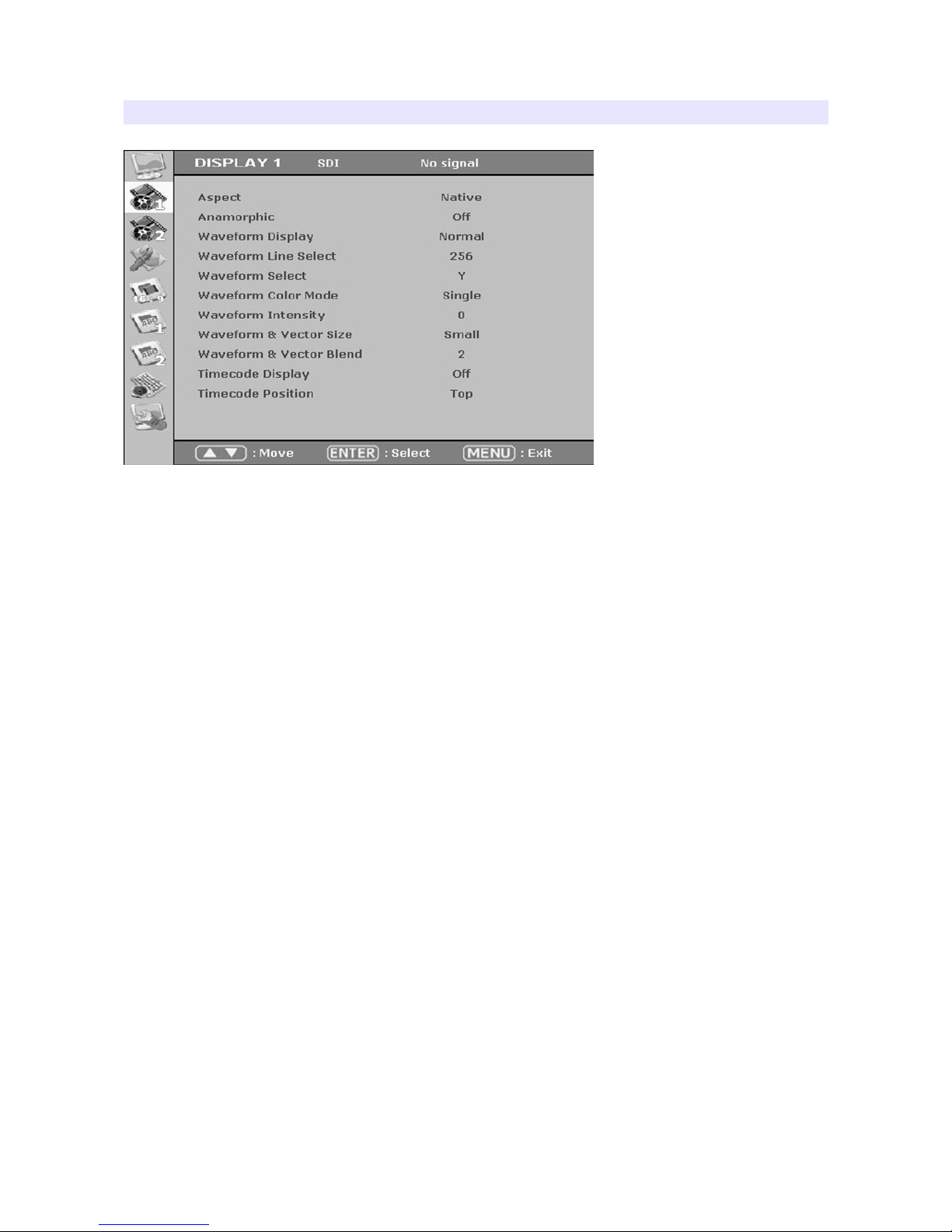
DISPLAY 1...........................................................................................................10
DISPLAY 2...........................................................................................................12
COLOR.................................................................................................................14
MARKER..............................................................................................................15
OSD 1...................................................................................................................17
OSD 2...................................................................................................................18
AUDIO..................................................................................................................20
SYSTEM..............................................................................................................22
Program Update Port (PGM)..............................................................................23
List of Compatible ideo Formats (HDMI).........................................................24
List of Compatible ideo Formats (SDI)............................................................25
Specifications......................................................................................................27
Dimensions..........................................................................................................28
Troubleshooting..................................................................................................29
Warranty Information..........................................................................................31
Modification of Product.......................................................................................31
Caution on Menu Operation................................................................................31
Caution for Monitor Placement...........................................................................31
2

Safety Instructions
•To help avoid damaging your monitor, connect only one power (AC or DC) in operation.
•Rough handling of product may cause physical damage or malfunction.
•Never insert anything metallic into the monitor openings. Doing so may create the danger of
electric shoc .
•To avoid electric shoc , never touch the inside of the monitor. Only a qualified should open the
monitor’s case.
•Openings in the monitor cabinet are provided for ventilation. To prevent overheating, these
openings should not be bloc ed or covered.
•Put your monitor in a location with low humidity and a minimum of dust. Avoid places li e
damp basement or dusty hallways.
•Place the monitor on a solid surface and treat it carefully. The screen is made of glass and can
be damaged if dropped or sharply hit.
•Do not attempt to remove the bac cover, as you will be exposed to a shoc hazard. The bac
cover should only be removed by qualified service personnel.
•Unplug the monitor power before you connect external devices to the monitor.
•If your monitor does not operate normally, or if there are any unusual sounds or smells coning
from it, unplug it immediately and contact us.
•Please do not disassemble the monitor. No service will be provided in that case.
•Displaying fixed picture for a long time may cause an afterimage or dead spots. To recover LCD
pixels, display whole white picture on screen for a n hour or two and pixels will be recovered.
•No service will be provided for user’s own color calibration.
3

Front Buttons
Focus Assist
Turn focus assist on to draw focus lines.
Marker
Turn focus assist on to draw focus lines.
oom
Switch zoom mode in the order of : Pixel to Pixel, User Zoom, DSLR Zoom
Pixel to Pixel
Shows the original picture with 1:1 pixel mapping. If the picture is larger than the monitor’s LCD
resolution, the center part of the picture is shown. Use nob to see a different part of the picture.
5 parts are selectable : CENTER, TOP-LEFT, TOP-RIGHT, BOTTOM-LEFT, BOTTOM-RIGHT.
User oom
This is a custom zoom mode which user can set the zoom level. Turn the nob to set your own
zoom level in this mode.
DSLR oom
This zoom-in/out preset allows fully scaled-up monitoring of contracted video from DSLRs. Zoom-
in/out area can also be customized to allow partial or full view.
To choose camera type, press Menu and choose Video, choose a DSLR camera type.
Daylight
This button switches luminance level in the order of : Indoor, Outdoor, Daylight, Auto. Press this
button to switch the luminance to see the screen shortly. Daylight mode provides maximum
4

luminance for sunlight visibility, which wor s more perfect on Bon Super Bright models. If you
choose Auto, the luminance changes automatically by the environment.
Menu
Displays the menu.
F1/▼
Launch function 1 assigned by user on the System menu, or it can be used as down arrow ey on
the menu.
F2/▲
Launch function 2 assigned by user on the System menu, or it can be used as up arrow ey on the
menu.
Adjust/Enter
Adjust volume, brightness, contrast, chroma, phase, or sharpess. Or it is used as Enter ey on the
menu.
5

Rear
DC Power Jack
7V ~ 17V DC power can be used.
SDI Input Port
HD SDI or SD SDI input port. SDI signal should be fulfill SMPTE standards.
SDI Out
SDI Out port used as Loop-Through port which bypasses SDI signal, or HDMI-to-SDI conversion out.
PGM (USB on the side)
PGM is a program update port for firmware.
Audio Level Meters
Audio level meters displays max 16 channels. But it depends on the number of channels contained
in the signal itself. For example, if the signal contains 2 channels, the audio level should be 2
channels.
The odd channels are displayed in the left, whereas the even channels are in the right. The position
of the meters can be set to top or bottom of the screen on the AUDIO section of the menu.
6

OSD Menu
Menu opens up by pressing Menu button. This button also works as Exit button on
the Menu. The brightness knob works as up/down arrow. To select something,
press either enter button or the knob.
* The menu may disappear on no signal or instable signal input.
* Menu setting is saved for each input mode. So the user should make
selection on an appropriate input mode.
VIDEO
Input Selection
Select input signal.
Brightness
Adjust brightness. Default: 127.
Contrast
Adjust contrast. Default: 127.
Chroma (Hue)
Adjust chroma. Default: 127.
Phase
Adjust phase. Default: 127.
7

Sharpness
Adjust sharpness. Default: 18.
SDI 3G Mode
Set this mode if the input is 3G HD SDI. SDI 3G mode support SMPTE standards listed below:
▶A_MS1_YCbCr422_10
: 3G SDI Level-A Mapping Structure 1 YCbCr 4:2:2/10 bit
▶A_MS2_YCbCr444_10
: 3G SDI Level-A Mapping Structure 2 YCbCr 4:4:4/10 bit
▶A_MS2_RGB444_10
: 3G SDI Level-A Mapping Structure 2 RGB 4:4:4/10 bit
▶A_MS3_YCbCr444_12
: 3G SDI Level-A Mapping Structure 3 YCbCr 4:4:4/12 bit
▶A_MS3_RGB444_12
: 3G SDI Level-A Mapping Structure 3 RGB 4:4:4/12 bit
▶A_MS4_YCbCr422_12
: 3G SDI Level-A Mapping Structure 4 YCbCr 4:2:2/12 bit
▶B_MS1_YCbCr422_10
: 3G SDI Level-B Mapping Structure 1 YCbCr 4:2:2/10 bit
▶B_MS2_YCbCr444_10
: 3G SDI Level-B Mapping Structure 2 YCbCr 4:4:4/10 bit
▶B_MS2_RGB444_10
: 3G SDI Level-B Mapping Structure 2 RGB 4:4:4/10 bit
▶B_MS3_YCbCr444_12
: 3G SDI Level-B Mapping Structure 3 YCbCr 4:4:4/12 bit
▶B_MS3_RGB444_12
: 3G SDI Level-B Mapping Structure 3 RGB 4:4:4/12 bit
▶B_MS4_YCbCr422_12
: 3G SDI Level-B Mapping Structure 4 YCbCr 4:2:2/12 bit
▶B_2X_DS1_YCbCr422_10
: 3G SDI Level-B Data Stream 1 YCbCr 4:2:2/10 bit, Dual Link SMPTE-372M
▶B_2X_DS2_YCbCr422_10
: 3G SDI Level-B Data Stream 2 YCbCr 4:2:2/10 bit, Dual Link SMPTE-372M
Especially for 3G Level signals, the format should be set manually.
Also, be aware that the format information might be lost on power down.
8

HDMI UV Swap
Sometimes UV signal might be opposite such input as PC RGB or such resolution as PC’s. Turn this
mode on to see correct color when the incorrect color displayed on this ind of input.
SDI Output
Set how to use SDI Out port. Choose either SDI loop-through or HDMI-to-SDI conversion out.
DSLR Camera
Set which DSLR camera you use for DSLR Zoom mode. DSLR Zoom mode can be set by pressing
Zoom button in the front.
9

DISPLAY 1
Aspect
Set the aspect ratio of the screen. 16:9, 4:3, Native(Original) are selectable.
Anarmorphic
Set this mode to resize the screen to 3.56:1, 2.74:1, 2.59:1, 2.55:1, 2.40:1, 2.39:1, 2.35:1, 1.85:1,
1.75:1, 1.66:1, or 1.37:1.
Waveform Display
Select waveform display mode. Choose Normal to analyze whole screen, choose Line Select to
analyze a specific line of the screen.
Waveform Line Select
Select the line when you select Line Select mode for Waveform display.
Waveform Select
Select which color signal to monitor among Y, Cb, or Cr.
Waveform Color Mode
Choose either Single or Mixed.
Waveform Intensity
Set waveform color’s intensity between 0~63.
10

WFM & Vector Size
Set Waveform and Vectorscope size among three inds.
WFM & Vector Blend
Set transparency of Waveform and Vectorscope window between 0~6.
YCbCr
YCbCr is a digital color reproduction standard. Y is for luminance, Cb
is for blue strength, Cr is for red strength.
Timecode Display
Set this mode on to display timecode from SDI signal. Select the appropriate timecode that you
wish to display among LTC (Longitudinal Time Code), VITC (Vertical Interval Time Code), DVITC
(Digital Vertical Interval Time Code).
Timecode Position
Set Top or Bottom position for timecode.
11

DISPLAY 2
Exposure Range Check (Video Range Check)
Chec s Y, C level and displays over-exposed or under-exposed area on screen. The base value can
be Y, Cb, or Cr.
Y Range Max / Min
Set Y range value for range chec .
C Range Max / Min
Set C range value for range chec .
Blink Color
The filled area color by range chec can be either Blac , Blue, Green or Red.
Blink Time
Set blin ing time of the area between 1 to 5 seconds.
False Color
Shows pictures in specific colors as its luminance level other than the original colors. Much
exposed area is filled with red while little exposed area is purple.
* 10-bit, 12-bit Dithered gradient pattern might not be displayed
clearly in this mode.
12

DISPLAY 2 (Focus Assist)
Focus Assist
Turns on Focus Assist mode. This mode can be set also by pressing Focus Assist button in front.
Focus Assist Box
Adjusts the size of the focus area box. Select among Small, Medium, Full, and user-adjustable
User1, User2.
Focus Assist Color
Set brush color of focus assist mode among White, Blue, Green, and Red.
Focus Assist Level (Sensitivity)
The sensitivity of the focus assist function can be set between 0 to 48.
Focus Assist Reverse
Un-focus area is highlighted instead of focus area.
Focus Assist Position
Focus area can be placed Center, Left Top, Center Top, Right Top, Right Center, Right Bottom,
Center Bottom, Left Bottom and Left Center.
13

COLOR
Dithering
Set this mode on to display gradient more smoothly.
Auto Color Temperature
Set this mode on to adjust color temperature by temperature change. Its output might incorrect on
some harsh environment.
Color Temperature
VAR, 3200K, 5600K, 6500K, 9300K color temperatures are preset and selectable by user. On User
mode, user can adjust RGB gain and bias. Adjusting on User mode is recommended to professional
users.
14

MARKER
Marker Ratio
Select one of preset mar ers or user mar er. To display mar er, press Mar er button in front of the
monitor.
Center Marker
Set preference to display center mar er or not.
Safety Area 16:9
Adjust size of the safety area when mar er displayed on 16:9 screen.
Safety Area 4:3
Adjust size of the safety area when mar er displayed on 4:3 screen.
Marker Color
Select mar er’s color among White, Red, Green, Blue, Gray and Blac .
Marker Mat
Set how to display outside of the safety area. Normal, Half(Gray), Blac are selectable.
Marker Thickness
Set mar er thic ness between 1 to 10.
User Marker H1 / User Marker H2 / User Marker V1 / User Marker V2
Set user mar er’s position. H1 for left, H2 for right, V1 for top, V2 for bottom. The positions are
15

saved as the selected mar er name such as USER1.
16

OSD 1
OSD Display Time
Set OSD menu display time. Choose 0 for infinite.
OSD Blend
Set transparency of the menu between 0 to 5.
OSD(Menu) Position
Set menu position among Left Top, Right Top, Left Bottom, Right Bottom and Center.
Internal Pattern
To test monitor display without signal, turn this mode on. Several patterns such as Color Bars, Blue,
Green, Red, White and Blac are selectable.
IMD Display
Set this mode on to display IMD text on screen.
IMD Color
Select IMD text color among Red, Green, and Amber.
IMD Edit
Set the IMD source ID to display on screen.
17

OSD 2
H/V Level Meters
Displays the horizontal and vertical angle on screen.
H/V Level Position
Sets the position of level meters.
H/V Size
Sets large or small level meter size.
H/V Sensitivity
Sets the sensitivity of level change.
Flip/Level Reset
Resets the flip and angle meters.
Battery Check
Turns on battery level chec er display.
Auto Flip
Automatic flip when monitor upside is down.
Tally Display
Displays tally signal on the top of LCD.
18

Tally Operating Level
Sets tally input level.
Low (Open) : below 0.6V, Green + Blac (GND)
High : over 2.5V, Red(5V) + Green
Caution : Do NOT use Red(5V) + Black(GND). It can cause electric shock on the onitor.
Tally Color
Sets tally color among Red, Green, Amber.
Example Picture of Tally Cable
Pin Assignment
1 RED +5V
2 Not Connection
3 Not Connection
4 GREEN TALLY IN
5BLACK GND
19

AUDIO
Audio Level Meter Display
Turns on/off audio level meters.
Level Meter SDI Channel
Set the audio channels to display.
Level Meter Type
Select one of two types: pair or group.
Level Meter Direction
Select one of two orientations : Horizontal or Vertical.
Level Meter Size
Select the size of the meters : Small or Large.
Level Meter Position
Select the position of the meters : Upper or Lower.
Peak Hold Decay Time
Set the decay time of the meters.
3G Level B Audio
Select one audio signals when there are two inputs.
20
Table of contents
Other bon Monitor manuals