BoonDocker Turbo Control Box User manual
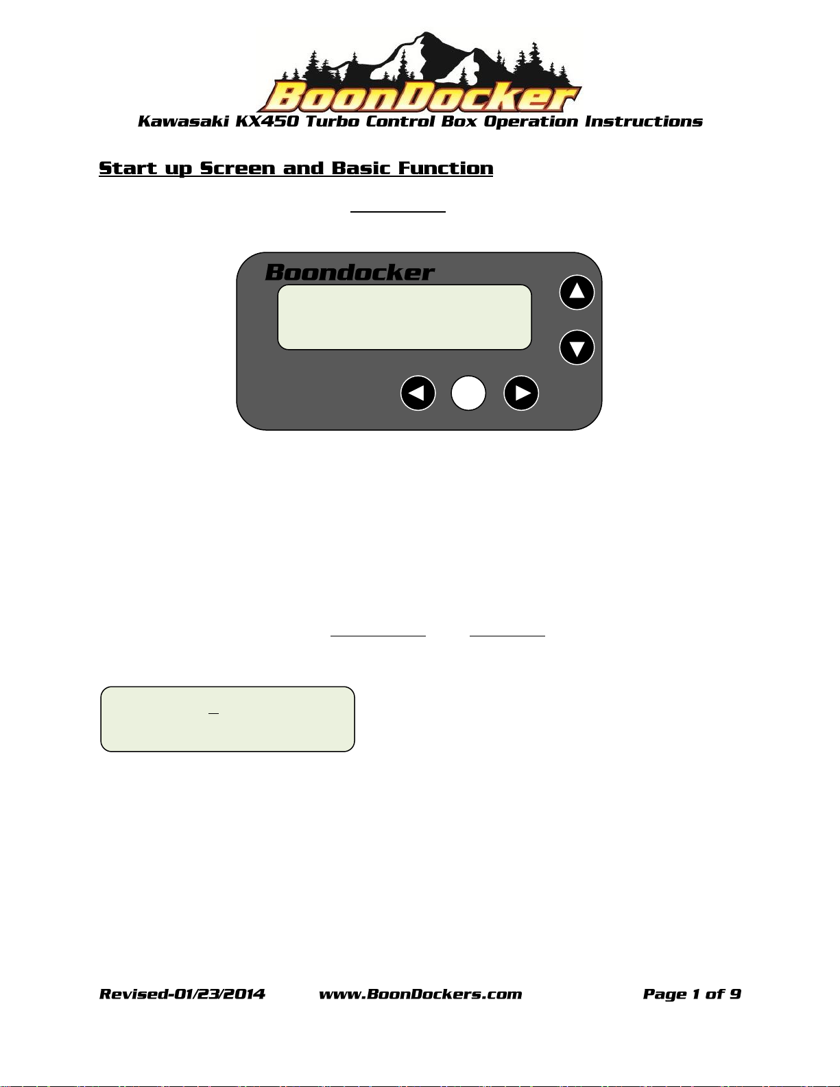
When the control box is powered up the Start Up Screen will be displayed.
There are five buttons used to navigate through the Boondocker Control box.
Left Arrow Button
Select (SEL) Button
Right Arrow Button
Up Button
Down Button
Push any button to advance from the Start Up Screen to the Main Menu.
Use the arrow buttons to move the →(cursor), up, down, left or right.
Once the →(cursor) is next the desired menu item press the SEL button to advance to that screen.
MAIN →FUEL Stats
MENU Xtra # 5.0
SEL
KX450F Turbo
5B2iBD2m 17.0
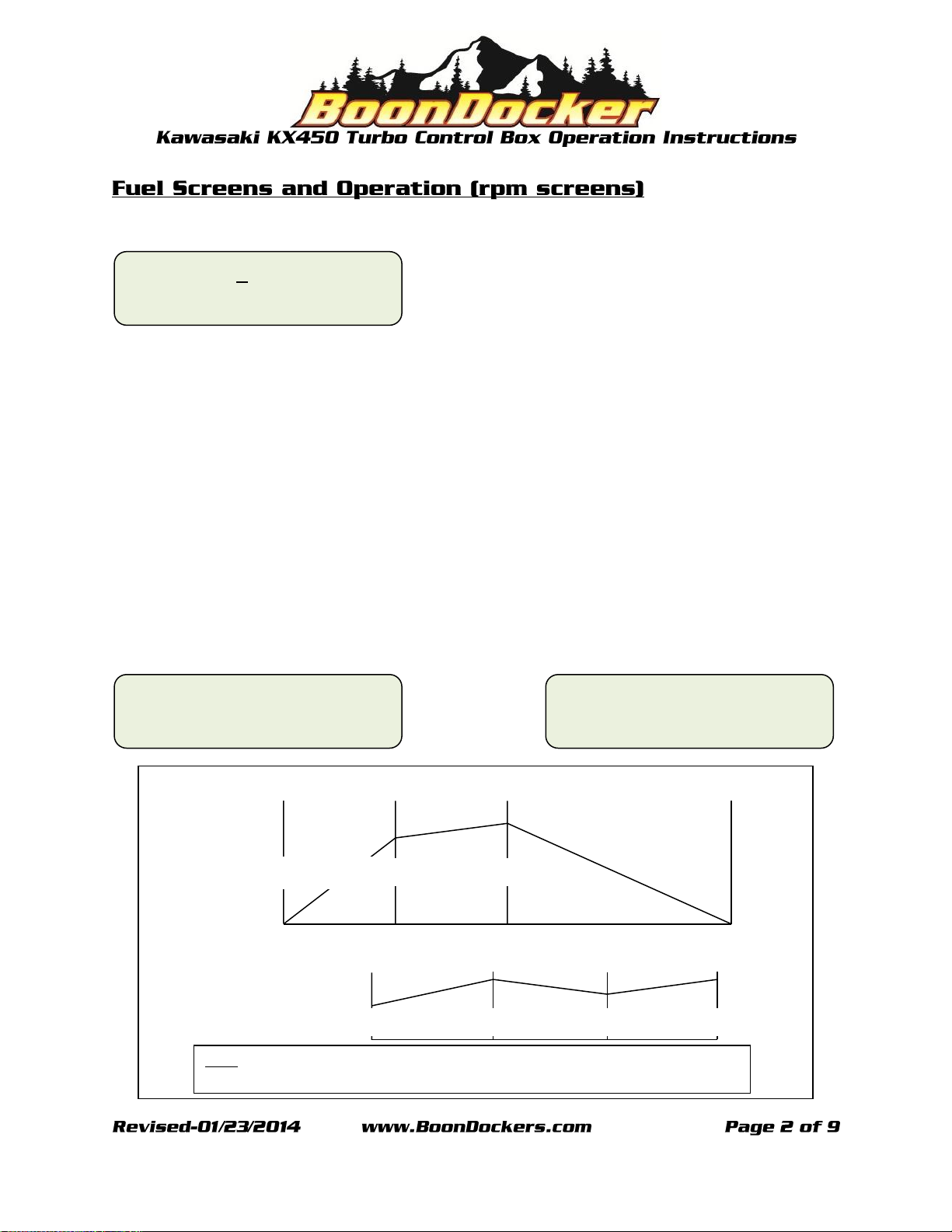
Position the →(cursor) next to “FUEL” and press the SEL button to advance to the first fuel “rpm”
screen.
There are two fuel (rpm) screens. These screens will allow the user to make fueling adjustment
according to RPM only. The values set in these two rpm screens will adjust fueling according to the
corresponding RPM ranges regardless of boost pressure. Each of the fuel screens are labeled with that
screen’s corresponding RPM in the lower left hand corner of the display and have four adjustment
points: 0, 33, 66, and 99. These adjustment points represent a given throttle position (TPS) percentage,
0% being no throttle and 99% being full throttle. The two digit number below each TPS value represents
the amount of fuel that will be added (or subtracted) to the given RPM and TPS range. Each of the RPM
ranges blend into each other and taper off to zero as demonstrated in the RPM figure below. Each TPS
range blends to the previous and next adjustment point as demonstrated in the TPS figure below.
To make adjustments, use the left and right arrow buttons to position the →(cursor) next to the
appropriate TPS value and use the up and down buttons to increase or decrease the fuel value.
To advance to the next screen press the SEL button.
rpm →
0 33 66 99
3000 00 00 00 00
rpm →
0 33 66 99
5000 05 05 -05 -15
MAIN →FUEL Stats
MENU Xtra # 5.0
TPS
66
0
99
33
Adjustable Values
05
10
07
11
Note: The adjustable values displayed are only samples, intended to illustrate the manner in
which these values will affect the blending in each region.
00
00
4500
0
5500
6700
RPM
07
10
Applied (TPS) Values

There are five fuel (psi) screens. These screens allow the user to make fueling adjustments for boost.
Each of the fuel screens are labeled with that screens corresponding RPM in the lower left hand corner
of the display and has four adjustment points 0, 33, 66, and 99. These adjustment points represent a
given throttle position (TPS) percentage, 0% being no throttle and 99% being full throttle. The adjustable
two digit numbers below each TPS value represents the amount of fuel that will be added to the given
RPM and TPS range. The values set in these psi screens will adjust fueling according to the
corresponding RPM and TPS ranges while automatically factoring in boost pressure. Each of the RPM
ranges blend into each other as demonstrated in the RPM figure below. Each TPS range blends to the
previous and next adjustment point as demonstrated in the TPS figure below.
To make adjustments, use the left and right arrow buttons to position the →(cursor) next to the
appropriate TPS value and use the up and down buttons to increase or decrease the fuel value.
To advance to the next screen press the SEL button.
psi →
0 33 66 99
6000 08 18 11 00
psi →
0 33 66 99
4300 05 05 00 00
psi →
0 33 66 99
7500 16 16 22 18
psi →
0 33 66 99
8700 14 22 35 40
psi →
0 33 66 99
10K 19 35 40 45
Note: The adjustable values displayed are only samples, intended to illustrate the manner in
which these values will affect the blending in each region.
TPS
66
0
99
33
Adjustable Values
05
10
07
11
RPM
5500
4300
7500
6700
8200
05
07
10
11
12
Applied (TPS) Values

Note: (The ACEL feature is useful for precise tuning, and if misused can create a wide range of tuning
issues. ACEL adjustment should only be made after all other tuning parameters have been properly
adjusted. ACEL adjustments should only be made by persons with an in-depth knowledge of tuning and
Boondocker control box use.)
The ACEL feature is an electronic accelerator pump that can be used to add (or subtract) fuel according
to throttle movement. When the throttle position is advanced (opened) the ACEL is activated.
Sensitivity (SN): The set sensitivity determines how far or fast the throttle position should be advanced
before the ACEL is activated. The value set below SN will determine the sensitivity, 01 being the most
sensitive and 10 being the least sensitive, 00 being on all of the time.
Amount (AL/AH): The set amount determines the amount of fuel that will be added (or subtracted)
when the ACEL is activated. The value set below AL will determine the amount of fuel that will be added
when the engine is being operated below 2.0 psi of boost. The value set below AH will determine the
amount of fuel that will be added when the engine is being operated above 2.0 psi of boost.
Duration (DR): The set duration determines the amount of time (number of engine cycles) the ACEL
feature will add or subtract fuel each time the ACEL is activated.
RPM →AL DR SN AH
ACEL 00 00 08 00
The extra (Xtra) screen contains features that can be used to add or subtract fuel when the adjustable
specified parameters for PSI and RPM are met. Auxiliary button parameters can also be adjusted in the
Xtra screen.
Position the →(cursor) next to Xtra and press the SEL button to advance to the extra screen.
The adjusted FUEL value will determine the amount of fuel that will be added or subtracted when the
auxiliary button is pushed if button is set to TUN. Note: (The Btn Tun FUEL value can be set from this
screen only when Btn is set to TUN, otherwise the screen will be advanced to the LO, MD, HI screen to
make FUEL adjustments for the PSI and RPM parameters.) To adjust parameters position the →(cursor)
below the desired parameter, FUEL, PSI or RPM or Btn and press select.
The LO, MD, HI in the Xtra FUEL menu represent throttle position LO being the first third, MD being the
middle third and HI being the last third of the throttle range. Note: (Btn cannot be set to TUN to access
this screen)
The PSI or RPM parameter can be turned on or off using the up and down arrow buttons with the
→(cursor) positioned next to the (OFF/ON) below PSI or RPM.
When the PSI Xtra is ON fuel will be added or subtracted only when the boost pressure is less than the
adjusted value. To adjust the less than PSI value use the up and down arrow buttons with the →(cursor)
next to the PSI adjustable value.
When the RPM Xtra is ON, fuel will be added or subtracted only when engine rpm is between the
minimum and maximum adjusted values. To adjust the RPM minimum and maximum use the up and
down arrow buttons with the →(cursor) next to the Min or Max adjustable value.
Note: (The Xtra PSI feature should always be used in conjunction with the RPM Xtra feature.)
MAIN FUEL Stats
MENU →Xtra # 5.0
FUEL PSI RPM Btn
→000 OFF OFF Tst
PSI Xtra on if
→OFF PSI < 4.6
RPM Min Max
OFF←3900 5950
LO MD HI
→000 000 000
There are four functions that can be assigned to an auxiliary button. Tst, +HP, TUN, and CAP. To assign a
function to the auxiliary button position the →(cursor) below Btn and use the up down arrow buttons to
toggle to the desired option.
Test (Tst): When set to Tst the auxiliary button can be used to test the auxiliary injectors. With the
engine idling if the auxiliary button is pushed the auxiliary injectors will spray, usually over fueling the
engine and causing the engine to die. Note: (To test injectors individually the opposite injector should be
unplugged while performing test.)
Tune (TUN): When set to TUN the auxiliary button can be used to momentarily add or subtract fuel
through the stock injectors. The amount of fuel added or subtracted is determined by the value set
below FUEL when Btn is set to TUN Tune. Note: The Tune feature can only function when the Xtra fuel
adjustments are not engaged. (Btn must be set to tune to access this adjustment. See page 5 for more
details.)
Capture (CAP): When set to CAP the auxiliary button can be used to capture statistics in the Stats
screens. With the engine running when the auxiliary button is pushed statistics will be captured in the
Stats Cp Screens (see Stats screen on page 7 for more details).
Description: Btn
Test AuxInj: →Tst
Description: Btn
Fuel only : →TUN
Description: Btn
StatCapture: →CAP

Statistics (Stats) screens display information that can be very useful.
Position the →(cursor) next to “Stats” and press the SEL button to advance to the extra screen
Run screen: The Run screen displays live information when the engine is running. Stock injector duty
cycle (denoted by a small “S”), auxiliary injector duty cycle(denoted by a small “A”), boost pressure
(upper right), engine rpm (lower left), TPS percentage (lower middle) and charge air temperature °F
(lower right).
Capture (Cp) screens: Press the up or down arrow button when on the Run screen to display the ten
capture screens 0,1,2,3,4,5,6,7,8, and 9 (Press the right arrow button to return to the Run Screen). When
Btn is set to CAP in the Xtra menu, a capture series can be started with the engine running by pushing
the auxiliary button. When the button is pushed the capture feature is armed, when the button is
released a statistics screen will be recorded every 7 engine cycles and can be reviewed in the Cp screens.
Note: (The left arrow button can be used a capture button if an auxiliary button is not present.)
Maximum (MAX) Screens: There are two MAX screens. The first MAX screen displays maximum rpm,
stock (Stk) injector duty cycle and auxiliary (Aux) injector duty cycle. The second MAX screen displays
maximum boost pressure (PSI) and charge air temperature (Temp). To clear MAX screens position the
→(cursor) next to (Y) and press the SEL button.
MAIN FUEL →Stats
MENU Xtra # 5.0
Run00
S
00
A
0.0
0000 tps99 00
F
°
Cp100
S
00
A
0.0
0000 tps99 00
F
°
MAX Stk Aux Clr
0000 00 00 →Y N
MAX PSI Temp Clr
0.0 00 →Y N
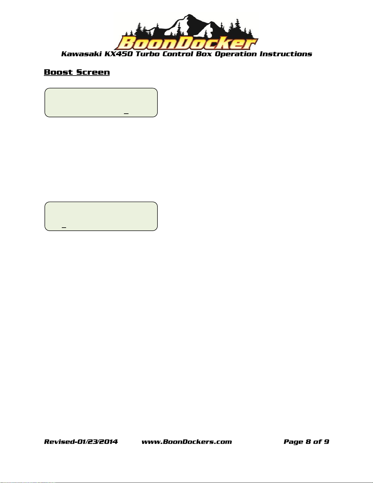
Position the →(cursor) next to # and press the SEL button to advance to the boost screen.
Boost screen: The boost screen has two adjustable values: Psi and Btn. The Psi value can be set to the
desired boost pressure. Once the desired boost pressure has been set, the Boondocker control box will
automatically adjust boost for changes in atmospheric pressure such as changes in elevation. Note: (The
minimum achievable boost pressure will be dependent on the waste gate actuator.)
Button (Btn): The value set below Btn is the amount of boost that can be momentarily added by pushing
the auxiliary button, when Btn is set to +HP in the Xtra menu (see page 6 for more details).
MAIN FUEL Stats
MENU Xtra →# 5.0
Psi Btn
5.0←2.0

Boost Solenoid Installation
Install the boost solenoid in a pressure line between the air box (or charge tube) and wastegate
actuator. Attach the metal port of the solenoid with a 3/16” hose to the air box (or charge tube) fitting
(see the figure below). Connect the right-angle port of the solenoid with a 3/16” hose to the wastegate
actuator. Attach a short length of hose to the third port and point it downward so that it won’t get
water in it. This is the actuator vent hose. Attach the solenoid so that it is supported. Use small zip ties
to secure the hoses to the ports.
This manual suits for next models
1


