Bortoluzzi Slider m User manual
sistema di scorrimento complanare
coplanar sliding system

the Company
Bortoluzzi Sistemi has been
manufacturing furniture for more than
fifty years, and its products have always
been characterised by exclusive projects.
The company is specialised in developing
sliding and locking technical solutions
for furniture and furniture accessories as
well as in manufacturing aluminium frame
wings and custom furniture on clients’
design. Bortoluzzi Sistemi’s advantage
is based on the creation of flexible
products that match customers’ needs
and expectations. Solutions entirely built
according to customers’ directions,
both in case of standard models and
for custom designs. The productive
process starts in the research and
development department, where projects
are developed by the highly qualified
technical staff through continuously
updated IT facilities, and then continues
in the production department, organized
on account of modern strict operating
rules. An innovative order system
completes the process. Orders can be
taken on the website on account of each
customer’s requirements: an additional
service provided by Bortoluzzi Sistemi
that further proves the company’s goal to
develop highly technical, reliable products
with timely delivers and exclusive
projects.
das Unternehmen
Kundenspezifische Maßarbeit ist ein
Merkmal, das seit jeher die Firma
Bortoluzzi Sistemi auszeichnet. Unser
Unternehmen arbeitet schon seit
mehr als fünfzig Jahren im Bereich
der Möbelindustrie und wir haben uns
auf neue und qualitativ hochwertige
Technologien für Türöffnungen und
Laufmechanismen von Möbeln und
anderen Einrichtungselementen
spezialisiert. Auch bei der Fertigung
von Türflügeln mit Aluminiumrahmen
und kundenspezifischen Anfertigungen
liegt unser großes Plus darin, daß
unsere Produktion extrem flexibel ist
und so allen Kundenanforderungen
gerecht werden kann. Das gilt sowohl
bei unseren Standardmodellen,
als auch bei Maßanfertigungen.
Möglich wird das dadurch, daß jedes
Projekt in unserer Entwicklungs- und
Forschungsabteilung “geboren” wird.
Wir können sowohl auf die langjährige
und kompetente Berufserfahrung
unserer Mitarbeiter zählen, als auch
auf modernste Informatiksysteme und
eine Produktionsabteilung, die nach
neuesten und effizient durchorganisierten
Richtlinien arbeitet. Bei uns haben die
Kunden außerdem die Möglichkeit, auf
problemlose und schnelle Weise ihre
Bestellungen mit allen spezifischen
Anforderungen und Daten aufzugeben,
und zwar über unsere Internetseite: das
ist ein Schritt mehr, mit dem unsere Firma
Bortoluzzi Sistemi unter Beweis stellt, auf
höchstem technischem Qualitätsstandard
zu arbeiten. Und natürlich können wir
unseren Kunden somit auch garantieren,
pünktlich exklusive Produkte zu liefern.
l’Azienda
L’esclusività del progetto è da sempre
ciò che maggiormente caratterizza
la produzione di Bortoluzzi Sistemi,
un’azienda con oltre cinquant’anni
di esperienza nel settore del mobile.
Specializzata nella realizzazione di
soluzioni tecnologiche per la chiusura
e lo scorrimento di mobili ed elementi
d’arredo e oggi anche nella produzione
di ante con telaio in alluminio e mobili finiti
su progetto del cliente, Bortoluzzi Sistemi
basa infatti la propria forza soprattutto
sulla creazione di prodotti flessibili alle
esigenze e alle aspettative del cliente.
Sia che si tratti di modelli standard
che di soluzioni su misura, costruite
interamente secondo le indicazioni del
committente. Il processo produttivo
che rende possibile questo risultato
ha inizio nel reparto ricerca e sviluppo,
dove vengono elaborati i progetti
grazie a personale tecnico altamente
specializzato e a strutture informatiche
in continuo aggiornamento, e prosegue
nell’area produzione, organizzata
secondo criteri operativi moderni e
rigorosi. Completa il processo un
metodo innovativo di raccolta dell’ordine,
effettuabile direttamente dal sito sulla
base delle specifiche richieste dal singolo
cliente: un ulteriore servizio offerto da
Bortoluzzi Sistemi a riprova del marcato
orientamento aziendale verso un prodotto
garantito da affidabilità tecnica, puntualità
di consegna ed esclusività progettuale.

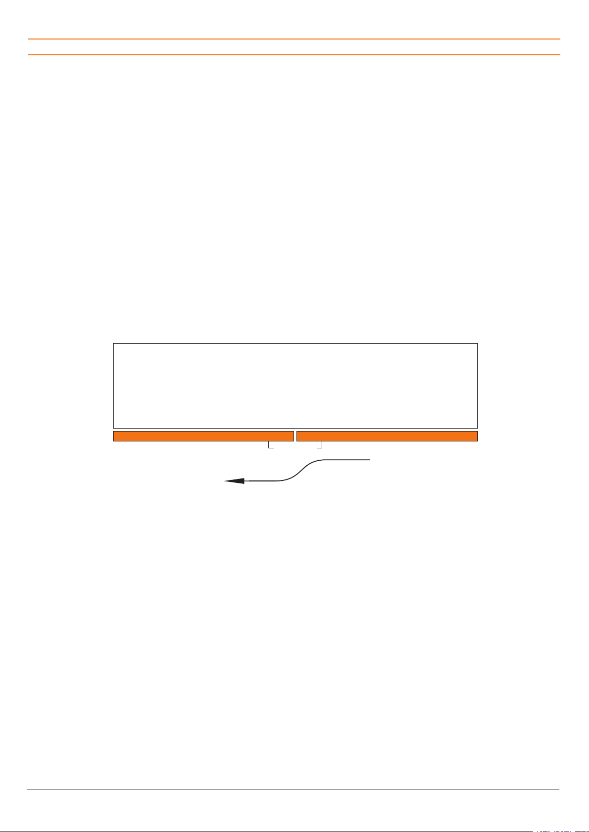
This table includes the variables required to
design the piece of furniture to which the
selected Slider Medium system applies.
Based on this information, Bortoluzzi Sistemi
will provide reports about the finishings to be
performed on the furniture panels.
Additional information is available on the
website www.bortoluzzi.com/slider, where
you can view a 3D simulation of the finished
piece of furniture or define a purchase order.
LEGENDA CODICI E SPECIFICHE NECESSARIE PER L’ORDINE
LEGEND OF NECESSARY CODES AND SPECIFICATIONS FOR ORDER
KODELEGENDE UND NÖTIGE DETAILS FÜR DIE BESTELLUNG
Nella presente tabella sono indicate le variabili
necessarie per la progettazione del mobile sul
quale applicare la tipologia di Slider Medium
prescelta. Sulla base di tali informazioni Borto-
luzzi Sistemi fornirà gli elaborati riguardanti le
lavorazioni da eseguire sui pannelli del mobile.
Ulteriori informazioni sono disponibili sul sito
internet www.bortoluzzi.com/slider, dove
è anche possibile effettuare una simulazione
tridimensionale del mobile finito o perfezionare
l’ordine di acquisto.
Diese Tabelle listet die Variabeln auf, die
zum Entwurf des Möbelstückes für die
Einsetzung des ausgewählten Slider-Systems
notwendig sind. Aufgrund dieser Informationen
wird Bortoluzzi Sistemi Berichte über die
Bearbeitungen, die auf den Möbelplatten
auszuführen sind, liefern.
Weitere Informationen finden Sie auf der
Webseite: www.bortoluzzi.com/slider, wo
eine 3D-Möbelsimulation zur Verfügung steht
und ein Kaufauftrag erteilt werden kann.
COD.
DESCRIZIONE VARIABILI
DESCRIPTION OF VARIABLES
MÖGLICHKEITEN
Type A Type B
LT Larghezza totale mobile
Total width of cabinet
Gesamter Schrankkorpusbreitenmaß
• •
HT Altezza totale mobile
Total height of interior of cabinet
Gesamter Schrankkorpushöhenmaß
• •
HI Altezza vano interno mobile
Height of interior of cabinet
Innen Schrankkorpushöhe
• •
SPA Spessore anta
Thickness of door
Türstärke
• •
SPAM Spessore anta + maniglia
Thickness of door + handle
Türstärke + Griff
• •
SPB Spessore base
Thickness of bottom panel
Untere Korpusplattenstärke
• •
SPC Spessore cielo
Thickness of top panel
Obere Korpusplattenstärke
• •
SPE Spessore spalla esterna
Thickness of side panel
Seiten Korpusstärke
• •
SPI Spessore spalla centrale
Thickness of centre panel
Mittelseite Korpusstärke
• •
SAE Sormonto anta su spalla esterna
Superimposition of door on side panel
Tür vor Aussenseiten
•
RM Rientro maniglia dal bordo anta
Recess of handle from edge of door
Griffabstand von seitliche Kante
• •
RAS Rientro anta dalla struttura
Recess of door from structure
Türabstand von Struktur
•
AA Distanza spalla centrale-anta in apertura
Central shoulder-wing distance when open
Abstand Mittelstruktur geöffneter Türflügel
• •
DYPL Distanza fianco-piedino in profondità
Side-foot distance in depth
Tiefenmassiger Abstand Seitenstruktur Fuß
• •
DXPL Ingombro piedino dal fianco
Feet room on side
Ausmaß Fuß aus seitlicher Ansicht
• •
BASE Fissaggio guida inf. dall’interno del mobile
Lower guide fixing from within the cabinet
Montage der unteren Führungsschiene vom Möbelinneren
SI / NO
YES / NO
JA / NEIN
SI / NO
YES / NO
JA / NEIN
DAMP Rientro anta ammortizzato
Amortized wing retraction
Gefederter Einzug Türflügel
SI / NO
YES / NO
JA / NEIN
SI / NO
YES / NO
JA / NEIN

Bortoluzzi Sistemi4
Colonne verticali / Vertical columns / vertikalen Säulen
È UN MOVIMENTO SCORREVOLE
PER DUE ANTE DI UGUALE
LARGHEZZA A CHIUSURA
COMPLANARE CHE TROVA
APPLICAZIONE SU COLONNE
VERTICALI.
IT IS A SLIDING MOVEMENT FOR
TWO WING WITH THE SAME SIZE,
COPLANAR LOCK, THAT CAN BE
APPLIED ON VERTICAL COLUMNS.
ES HANDELT SICH UM EIN
SCHIEBESYSTEM FÜR ZWEI
GLEICHBREITE TÜREN MIT
FLÄCHEN BÜNDIGE, BEWEGUNG
DIE NACH KONFIGURATION AUF
VERTIKALEN SÄLEN EINSETZBAR
SIND.
MOVIMENTO COMPLANARE A DUE ANTE
TWO DOOR COPLANAR SYSTEM / ZWEITÜRIGE, FLÄCHENBÜNDIGE SCHIEBESYSTEM

SLIDER 5
Scheda tecnica del prodotto / Product technical sheet / Technische Beschreibung
Brevetto per invenzione industriale
n. 0001337830 - Ministero dello
Sviluppo Economico
I movimenti sono composti da:
profili in alluminio: lega 6060T5
anodizzati argento ARC 10
guide per l’uscita delle ante: MDF con
finitura superficiale tipo alluminio
ruote di scorrimento: cuscinetti per
alta velocità rivestiti in materiale
plastico
componenti di traslazione e
regolazione: pressofusi in zama
primaria 13
I movimenti possono montare
ante che hanno le seguenti
caratteristiche:
peso massimo per singola anta: kg 35
larghezza: minima mm 600 - massima
mm 1800
altezza massima consigliata: mm 2200
spessore: minimo mm 18 - massimo
mm 45 (maniglia compresa)
materiale:
a) legno o derivati
b) vetro con telaio in alluminio
(interpellare la ditta produttrice per
verificare la fattibilità)
Pulizia dei movimenti: la pulizia dei
componenti deve essere eseguita con
acqua e sapone mediante un panno
morbido. Evitare prodotti contenenti
solventi e prodotti abrasivi.
Smaltimento: una volta dismesso, il
prodotto o i suoi componenti non vanno
dispersi nell’ambiente, ma conferiti ai
sistemi pubblici di smaltimento.
Patent number n. 0001337830
The systems include:
anodized ARC 10 silver
aluminium-like surface finishing
for high-speed performance
cast components in basic Zn+Al+Mg
13 alloy
The systems are suitable for the
following door types:
2200
a) wood or derived material
b) glass with aluminium frame (please
contact the manufacturer for
feasibility)
System cleaning: the parts can be
cleaned with a soft cloth using water
and soap. Do not use any solvents or
abrasive products.
Disposal: the product and its
components must not be disposed of in
the environment; for disposal please use
public disposal systems.
Patent number n. 0001337830
Die Schiebesysteme bestehen aus
folgende Einbauteilen:
eloxiert, Silber ARC 10
MDF mit Oberfläche aus Aluminium
ummantelt
Hoch-geschwindigkeitslager
aus 13-Zamakdruckguss
Die Schiebesysteme eignen sich für
Türen mit folgende Eigenschaften:
(inklusive Griffhöhe)
a) Holz oder Holzprodukte
b) Glas mit Aluprofile umrahmt (für die
Machbarkeit wenden Sie sich bitte
an den Hersteller)
Systemsreinigung: Ein weiches
Tuch mit etwas Wasser und Seife ist
das beste Reinigungsmittel für die
Einbauteile. Verwenden Sie keine
Chemikalien, aggressive Fleckenmittel
oder Scheürmittel.
Entsorgung: Produkte und Produkteile,
die nicht mehr zum Einsatz kommen,
sollen nicht in die Umwelt gelangen und
sind über in speziell dafür eingerichteten
Sammelstellen zu entsorgen.
Bortoluzzi Sistemi6
Tipologie aperture:
apertura di due ante uguali oppure
di un’anta unica su vano a giorno o
cassetti
l’ausilio di maniglie posizionate al
centro del mobile
Per aperture particolari non previste
contattare direttamente l’azienda
produttrice.
Nota: L’azienda produttice si riserva il
diritto di apportare modifiche tecniche
senza preavviso.
Openings types:
or single wing opening to an open
shelving unit or to a unit provided with
drawers are available
handle mounted in the middle of the
cabinet
For special opening types please contact
the manufacturer.
Note: The manufacturer reserves the
right to modify any product without prior
notice.
Öffnungstypen:
gleichbreiten Türen oder mit einer
einzigen Tür, die sich auf einen offenen
Raum oder ein Fach öffnen
Handgriffe, die inmitten der Möbeltür
montiert sind
brauchen, wenden Sie sich direkt an den
Hersteller.
Änderungen an den Produkten können
vom Hersteller ohne Vorankündigung
vorgenommen werden.
Scheda tecnica del prodotto / Product technical sheet / Technische Beschreibung

SLIDER 7
Kit Slider Medium / Slider Medium Kit / Slider Medium Kit
Il cliente riceverà:
a) Scatola contenente
binario di scorrimento superiore
con staffe per le ante
guida inferiore di scorrimento in
MDF
piastre centrali e laterali per guida
inferiore per anta destra e sinistra
chiave fissa da mm 10.
Customers will be provided with:
a) Case including
the doors
guide for left and right wings
M6 x 24
wrench.
Den Kunden wird das folgende
geliefert:
a) Packung mit
mit Aluwinkelplatte
untere Schiene des rechten und
linken Türflügels
Ausrichtungsbeschlägen für
mm - Maulschlüssel.
Bortoluzzi Sistemi8
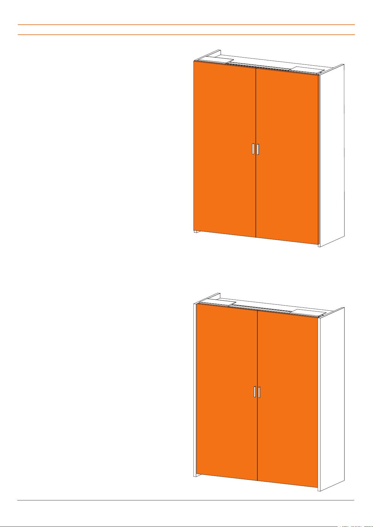
TIPOLOGIA A: Movimento con meccanismo di scorri-
mento superiore per ante a ridosso su
cielo, base e spalle esterne.
TYPE A: System with upper slide mechanism
for doors covering top, bottom and
side panels.
TYP A: System mit oberem Schiebesystem
für Türöffnung ver oberen, unteren und
aussenseiten stehend.
TIPOLOGIA B: Movimento con meccanismo di scor-
rimento superiore per ante a ridosso
su cielo, base e in luce tra le spalle
esterne.
TYPE B: System with upper slide mechanism for
doors covering top panel, bottom and
with side panels visible.
TYP B: System mit oberem Schiebesystem
für Türöffnung var Ober- und Unter-
platte und nach innen zu den Aussen-
seiten.
Tipologie Slider Medium / Slider Medium types / Slider Medium Typologien
SLIDER 9
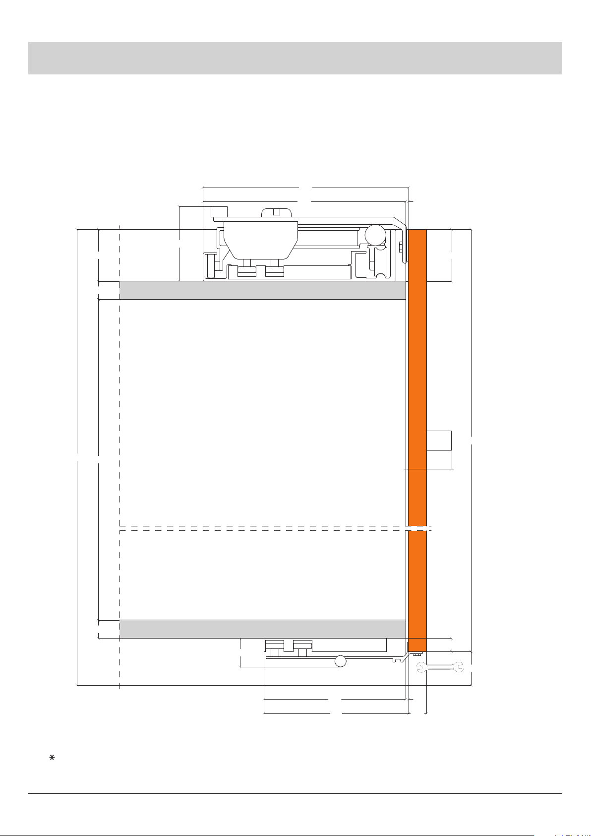
Spazio minimo per fissaggio piastre inferiori mm 35
Minimum gap for lower plate fixing mm 35
Minimalraum für die Montage der Unterplatten mm 35
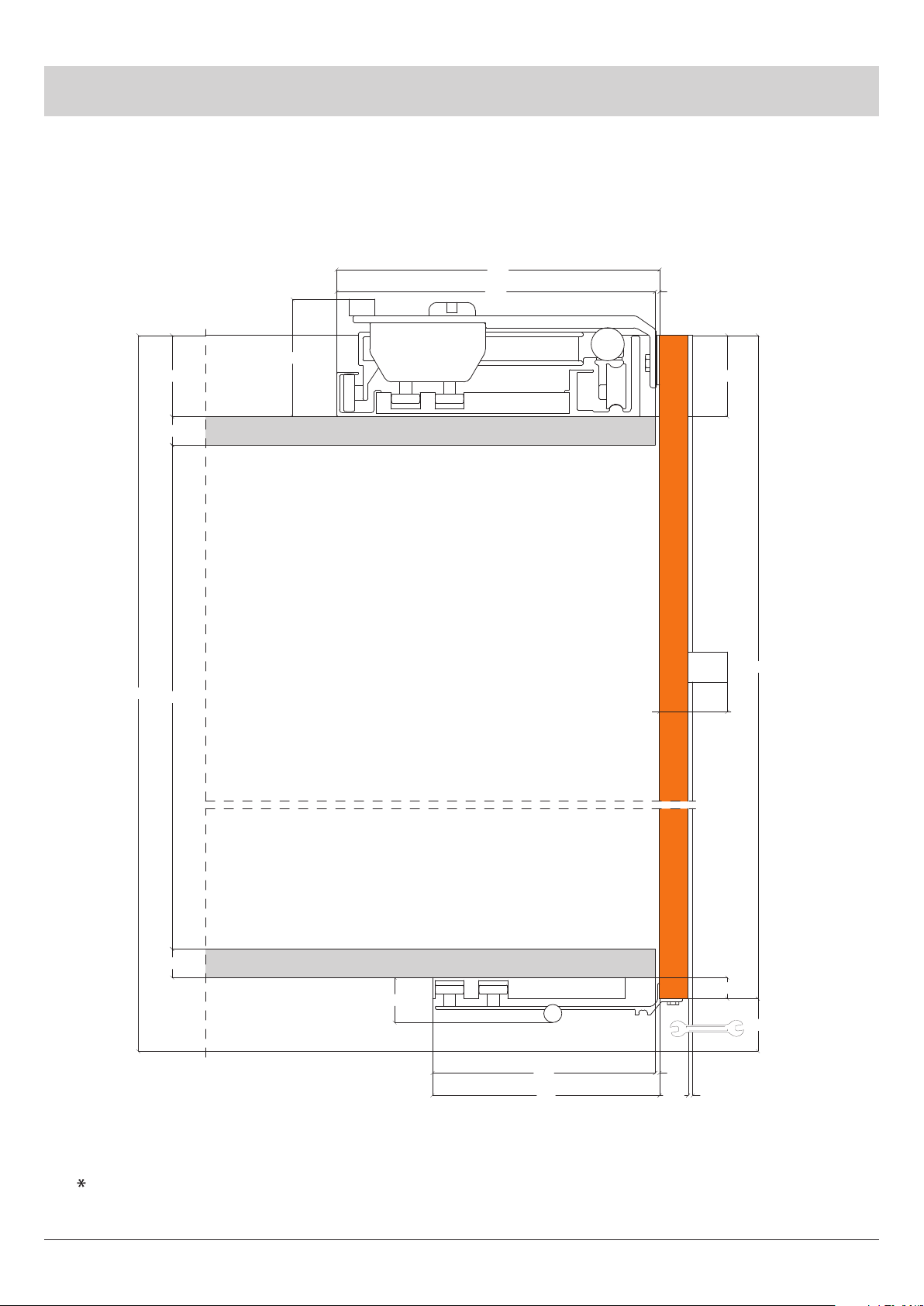
TIPOLOGIA “A”
TYPE A / TYP A
MOVIMENTO CON MECCANISMO
DI SCORRIMENTO SUPERIORE PER
ANTE A RIDOSSO SU CIELO, BASE E
SPALLE ESTERNE.
SYSTEM WITH UPPER SLIDE FOR
DOORS COVERING TOP, BOTTOM
AND SIDE PANELS.
SYSTEM MIT OBEREM SCHIEBE-
VOR
OBER, UNTER UND AUSSENSEITEN
STEHEND.
54
SPC
HI
SPB
HT
151
30
148 3
SPA
14
54
SPAM
HA
*
3212
215
78

Bortoluzzi Sistemi10
30% 30%
30)
,4
3!% 2- 2- 3!%
,! ,!
-).MM
$80, $80,
$90, $90,
!!
30% 30%
30)
,4
3!% 2- 2- 3!%
,! ,!
-).MM
$80, $80,
$90, $90,
!!
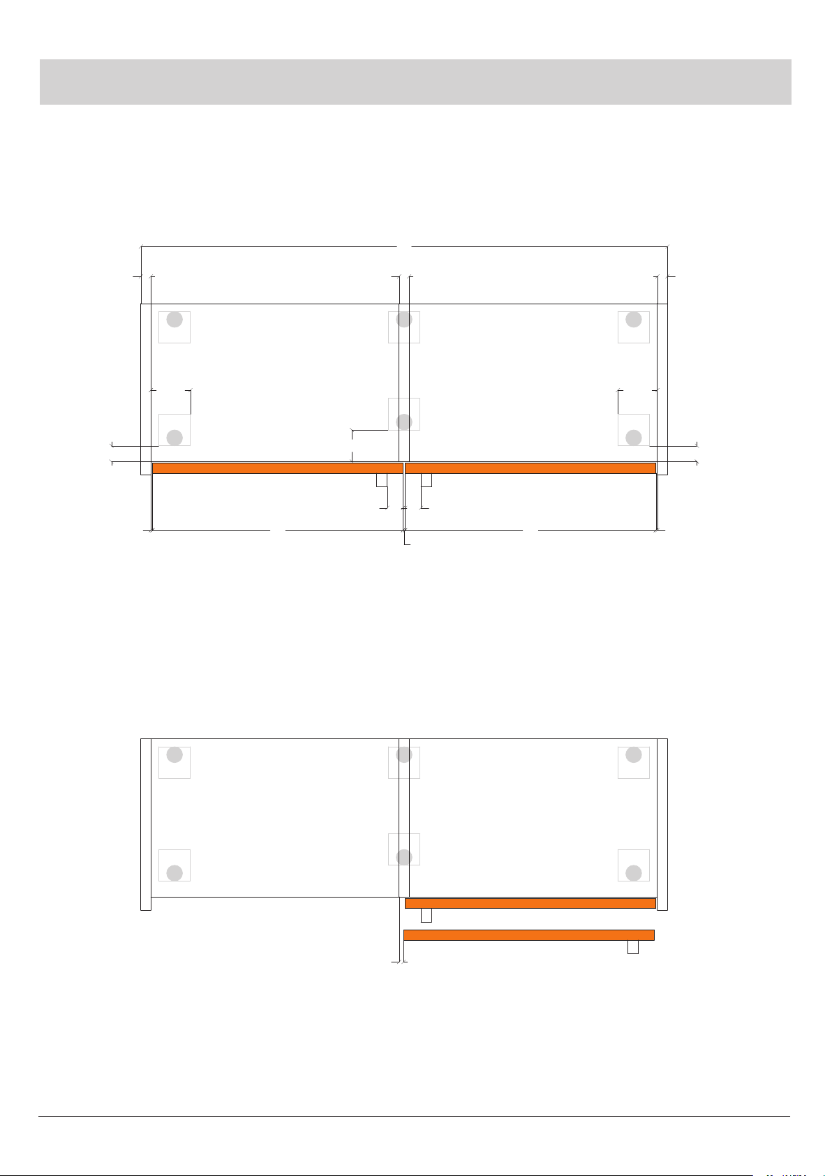
Apertura ante/Door opening/Türöffnung
TIPOLOGIA “A”
TYPE A / TYP A
Piedino laterale
Side foot
Seitlicher Sockelfuß
Piedino laterale
Side foot
Seitlicher Sockelfuß
Piedino centrale
Central foot
Mittelfuß
SLIDER 11
TIPOLOGIA “B”
TYPE B / TYP B
54
SPC
HI
SPB
HT
151
30
3
SPA
14
SPAM
HA
54
*
148
RAS
3212
215
78
spazio minimo per fissaggio piastre inferiori mm 35
Minimum gap for lower plate fixing mm 35
Minimalraum für die Montage der unterplatten mm 35
MOVIMENTO CON MECCANISMO DI
SCORRIMENTO SUPERIORE PER
ANTE A RIDOSSO SU CIELO, BASE E
IN LUCE TRA LE SPALLE ESTERNE.
SYSTEM WITH UPPER SLIDE FOR
DOORS COVERING TOP, BOTTOM
AND WITH SIDE PANELS VISIBLE.
SYSTEM MIT OBEREM SCHIEBE
VON OBER UND UNTERPLATTE
UND NACH INNEN ZU DEN
AUSSENSEITEN.
Bortoluzzi Sistemi12
TIPOLOGIA “B”
TYPE B / TYP B
Apertura ante/Door opening/Türöffnung
30% 30%
30)
,4
2- 2-
-).MM
,! ,!
$80, $80,
$90,
$90,
!!
30% 30%
30)
,4
2- 2-
-).MM
,! ,!
$80, $80,
$90,
$90,
!!
Piedino laterale
Side foot
Seitlicher Sockelfuß
Piedino laterale
Side foot
Seitlicher Sockelfuß
Piedino centrale
Central foot
Mittelfuß

SLIDER 13
Montaggio Slider Medium / Slider Medium assembly / Slider Medium Montage
IMPORTANTE
Mettere in bolla il contenitore sul quale
va applicato il sistema di scorrimento
SLIDER MEDIUM (vedi fig.100).
IMPORTANT
Level the cabinet which the sliding
system SLIDER MEDIUM is to be applied
to (see fig.100).
WICHTIG!
Die Oberschrankstruktur, auf dem
das Schiebesystem SLIDER MEDIUM
eingesetzt werden soll, ausrichten
(s. Bild 100).
fig.100
fig.101
Applicare il movimento SLIDER MEDIUM
e fissarlo al cielo con viti a legno TPS
di adeguata lunghezza nei fori già
predisposti sul movimento (vedi fig.101).
Install the SLIDER MEDIUM system and
fasten it to the ceiling with suitably long
TPS wooden screws into holes in the
mechanism (see fig.101).
Das SLIDER MEDIUM system einsetzen
und an der Decke durch angemessene
TPS - Holzschrauben in der dafür
vorbereiteten löchern befestigen
(s. Bild 101).

Bortoluzzi Sistemi14
Applicare la guida inferiore in MDF sotto
il basamento e fissarla, con viti a legno
TPS di lunghezza adeguata, dall’interno
del mobile (vedi fig.102) o da sotto
(vedi fig.103) a seconda della scelta al
momento dell’ordine (variabile “base”).
Montaggio Slider Medium / Slider Medium assembly / Slider Medium Montage
fig.103
Apply the MDF lower guide under the
base and fix it - using TPS wooden
screws with suitable length - from
inside (see fig.102) or from beneath (see
fig.103) the cabinet, on account of the
version selected (“BASE” variable).
Die untere MDF - Schiene unter
der Bodenplatte befestigen und
mit entsprechend langen, TPS -
Holzschrauben in Innenschrank
(s. Bild 102) oder von unten (s. Bild 103)
fixieren - je nach Wahl zum Zeitpunkt der
Bestellung (Variable “BASE”).
fig.102

SLIDER 15
Montaggio Slider Medium / Slider Medium assembly / Slider Medium Montage
regolatore verticale
vertical adjuster
senkrechter Ausrichtbeschlag
fig.104
regolatore orizzontale e verticale
horizontal and vertical adjuster
senkrechter und waagerechter
Ausrichtbeschlag
Nel caso di ante in legno, inserire il
regolatore verticale nella sede laterale
e quello orizzontale-verticale nella sede
centrale delle ante.
Fissarli poi con viti a legno TPS di
lunghezza adeguata allo spessore delle
ante (vedi fig.104).
Nel bordo inferiore delle ante, inserire
nei fori predisposti, le bussole M6 in
dotazione, per il fissaggio delle piastre.
In case of wooden wings, insert the
vertical governor into the central slot and
the horizontal-vertical governor into the
wing side slot.
Then tighten using TPS wooden screws
with a length suitable to the wing
thickness (please refer to fig.104).
Insert the M6 bushes supplied into the
special holes in the edges of lower wings
to fix plates.
In Fall von Holztüren, muß der vertikale
Ausrichtungsbeschlag am seitlichen Sitz
und der horizontal - vertikale am mittleren
Sitz der Türflügel angebracht werden.
Die Ausrichtungsbeschläge mit
angemessenen TPS - Holzschrauben,
befestigen (s. Bild 104).
Am unteren Rand der Türflügel werden
die mitgelieferten M6-Buchsen in
eingeführt, um die Platten zu fixieren.

Bortoluzzi Sistemi16
fig.105
regolatore verticale
vertical adjuster
senkrechter
Ausrichtbeschlag
regolatore orizzontale e verticale
horizontal and vertical adjuster
senkrechter und waagerechter Ausrichtbeschlag
Montaggio Slider Medium / Slider Medium assembly / Slider Medium Montage
Nel caso di ante con telaio in alluminio,
inserire il regolatore verticale nella sede
laterale e quello orizzontale-verticale nella
sede centrale delle ante.
Fissarli poi con viti TPS autofilettanti per
metallo (vedi fig.105).
Nel bordo inferiore delle ante, dovranno
essere predisposti filetti M5 o inserti
filettati M5, nelle posizioni indicate dagli
elaborati della Bortoluzzi Sistemi, per il
fissaggio delle piastre.
In case of aluminium frame wings, insert
the vertical governor into the side slot and
the horizontal-vertical governor into the
wing central slot.
Then tighten using TPS self-tapping
screws for metal with a suitable length
(see fig.105).
To fix plates, M5 threads or M5 threaded
insets shall be provided in the lower
edges of wings, according to the
positions stated in Bortoluzzi Sistemi’s
documents.
Sollten die Türflügel einen
Aluminiumrahmen haben, wird der
vertikale Ausrichtungsbeschlag in den
seitlichen Sitz und der horizontal -
vertikale in den mittleren Sitz der Türflügel
eingeführt.
Dann werden die Ausrichtungsbeschläge
mit entsprechenden selbstschneidenden
TPS - Schrauben für Metall befestigt.
(s. Bild 105).
Am unteren Rand der Türflügel müßen
für die Fixierung der Platten M5 -
Gewindegänge vorgerichtet oder M5
- Gewinde eingeführt werden - für die
korrekte Positionieren befolgen Sie dabei
bitte die Anweisungen, die Sie in den
Unterlagen Bortoluzzi Sistemi finden.

SLIDER 17
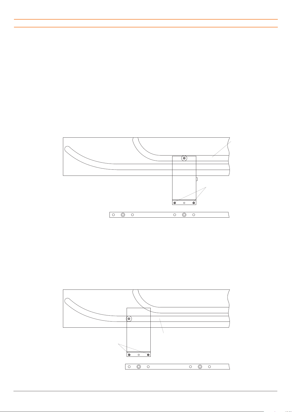
Estrarre una staffa superiore aprendola
fino a fine corsa.
Applicare la corrispondente anta
agganciando la testa esagonale della vite
sporgente dal regolatore centrale nella
sede ricavata sulla staffa (vedi fig.106).
Poi ruotare leggermente l’anta fino a
far entrare la testa esagonale della vite
sporgente dal regolatore laterale nell’altra
sede della staffa (vedi fig.106).
Quindi, con una chiave fissa da mm 10,
serrare le due viti a testa esagonale
(vedi fig.107).
Montaggio Slider Medium / Slider Medium assembly / Slider Medium Montage
Extract one of the upper brackets and
open it to the stop position.
Apply the corresponding wing by
clamping the hexagonal head of the
screw protruding from the central
governor to the central slot in the bracket
(see fig.106). Then gently rotate the wing
until the hexagonal head of the screw
protruding from the side governor enters
the other bracket slot (see fig.106).
Then tighten the hexagonal head screws
using a 10 mm wrench (see fig.107).
Einen der oberen Führungswinkel
abnehmen und ihn bis zum Anschlag
öffnen.
Den dazugehörigen Türflügel aufsetzen,
indem der sechskantige Schraubenkopf,
der vom zentralen Ausrichtungsbeschlag
absteht, in die dafür vorgesehene
(s. Bild 106). Dann wird der Türflügel
leicht gedreht, bis der sechskantige
Schraubenkopf, der vom seitlichen
Ausrichtungsbeschlag absteht, in die
einspringt (s. Bild 106).
Mit einem 10 mm - Maulschlüßel die
beiden sechskantigen Schrauben fest
anziehen (s. Bild 107).
fig.106
Sede per vite, regolatore centrale
Screw slot, central governor
Schraubloch, mittlerer Ausrichtungsbeschlag
Sede per vite, regolatore laterale
Screw slot, side governor
Schraubloch, seitlicher Ausrichtungsbeschlag
fig.107
Bortoluzzi Sistemi18
Ripetere lo stesso procedimento con la
piastra laterale infilando, in questo caso,
il cuscinetto nel binario anteriore della
guida (vedi fig.109).
Montaggio Slider Medium / Slider Medium assembly / Slider Medium Montage
fig.108
Der gleiche Arbeitsvorgang wird mit der
Seitenplatte wiederholt, wobei hier das
Lager in die vordere Schiene eingeführt
wird. (s. Bild 109).
Repeat the process with the side wing (in
this case insert the bearing into the front
track of the guide - see fig.109).
Dopo aver fissato le ante nella parte
superiore, posizionare la piastra inferiore
centrale (identificata dall’etichetta),
infilando il cuscinetto nel binario
posteriore della guida, precedentemente
avvitata sotto il basamento, e le spine
di posizionamento nei fori di riferimento
eseguiti nel bordo inferiore dell’anta.
Avvitare la vite TE M6 x 12 in dotazione
(vedi fig.108).
After fixing the door in the upper part,
position the lower central plate (identified
through its label) by sliding the bearing
into the rear rail of the guide (that was
screwed under the base), and the
positioning pins in the reference holes
on the wing lower edge. Screw the
TE M6 x 12 screw supplied (see fig.108).
Nachdem die Türe am oberen Beschlag
angebracht wurde, die untere Mittelplatte
positionieren (siehe Etikette); dabei muß
die Buchse in die Schiene eingeschoben
werden, die vorher unter der Bodenplatte
angeschraubt wurde, und die Dübel
müssen in die vorgebohrten Locher an
der Unterseite des Türflügels gesteckt
werden. Mit der mitgelieferten Schraube
TE M6 x 12 festziehen (s. Bild 108).
fig.109
Binario posteriore
Rear track
Hintere Laufschiene
Spine di posizionamento
Positioning pins
Positionierungsstift
Binario anteriore
Front track
Vordere Laufschiene
Spine di posizionamento
Positioning pins
Positionierungsstift
SLIDER 19
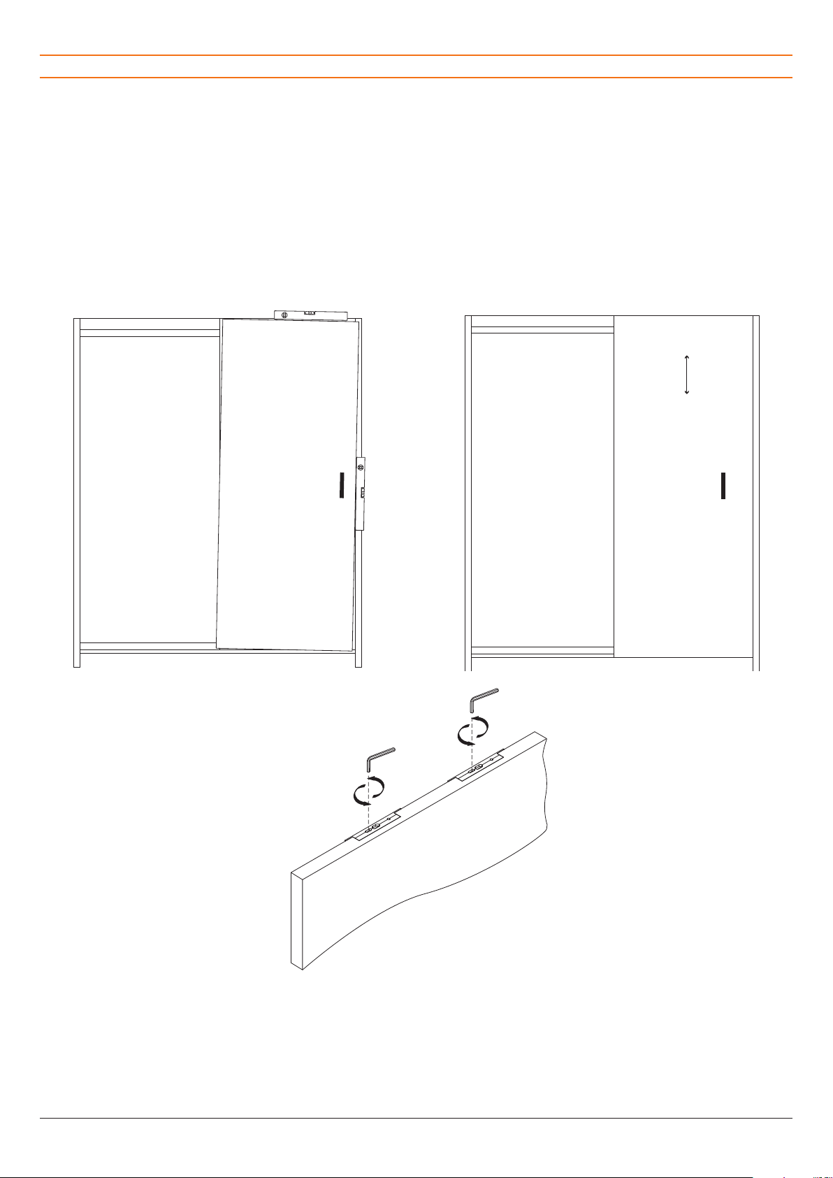
fig.112
IMPORTANTE
Aprire con cura la prima anta, facendola
scorrere fino a fine corsa (vedi fig.110)
e metterla in bolla agendo sui regolatori
verticali con la chiave esagonale da 3
mm in dotazione, nell’impronta di sinistra
(vedi fig.112).
Allo stesso modo, regolare la posizione
in altezza rispetto alla struttura (vedi
fig.111).
Ripetere le operazioni anche sulla
seconda anta.
IMPORTANT
Open the first wing with care by sliding
it until it stops (see fig.110), then level it
through the vertical adjustment system
using the 3 mm hexagon wrench
provided, in the left slot (see fig.112).
Similarly, adjust the height position
referred to the structure (see fig.111).
Repeat the same operations on the
second wing.
WICHTIG!
Den ersten Türflügel vorsichtig bis zum
Anschlag öffnen (s. Bild 110); an der
linken Gravur der Ausrichtungsbeschläge
mit dem mitgelieferten 3 mm -
Schraubenschlüßel waagrecht ausrichten
(s. Bild 112).
Genauso muß die Höhenposition
reguliert werden (s. Bild 111).
Das gleiche am anderen Türflügel
vornehmen.
Regolazioni / Adjustments / Regulierung
fig.110 fig.111
Verificare che lo scuretto tra le ante risulti
parallelo.
In caso contrario, AD ANTE CHIUSE,
agire sui regolatori verticali (vedi fig.112)
Check the shutter between wings is
parallel.
If it’s not, operate on parallel adjusting
systems when WINGS ARE CLOSED
(see fig.112)
Überprüfen Sie, ob der Laden zwischen
den Türflügeln parallel ist.
Ansonsten muß er BEI GESCHLOßENEN
TÜRFLUEGELN mit den senkrechten
Ausrichtungsbeschlägen reguliert
werden (s. Bild 112).

Bortoluzzi Sistemi20
fig.115
./
Regolazioni / Adjustments / Regulierung
Regolare lo scuretto di 4 mm tra le ante
(vedi figg. 113-114) e nel caso della
tipologia B anche lo scuretto di 4 mm
tra le ante e i fianchi laterali (vedi fig.114)
agendo sui regolatori orizzontali, applicati
al centro delle ante (vedi figg.104-105),
con la chiave esagonale da 3 mm in
dotazione, nell’impronta di destra (vedi
fig.115).
fig.114fig.113
Adjust the shutter by 4 mm between
wings (see fig.113-114) and, in case
of type B, even 4 mm between lateral
sides and wings (see fig.114) using the
horizontal adjusting systems, in the
centre of wings (see fig.104-105). Use
the 3 mm hexagon wrench provided, in
the right slot (see fig.115).
Den 4 mm Laden zwischen den
Türflügeln regulieren (s. Bilde
113-114). Bei Modell B muß sowohl
der 4 mm Laden zwischen den
Türflügeln als auch der an den
Seitenwänden reguliert werden (s.
bilde 104-105). Dabei verwendet
man den mitgelieferten 3 mm
Schraubenschlüssel und agiert an der
rechten Gravur (s. Bild 115).
Other Bortoluzzi Door Opening System manuals


