RollSeal RS-500 WIC Setup guide

4802-7536C 1 15 November 2021
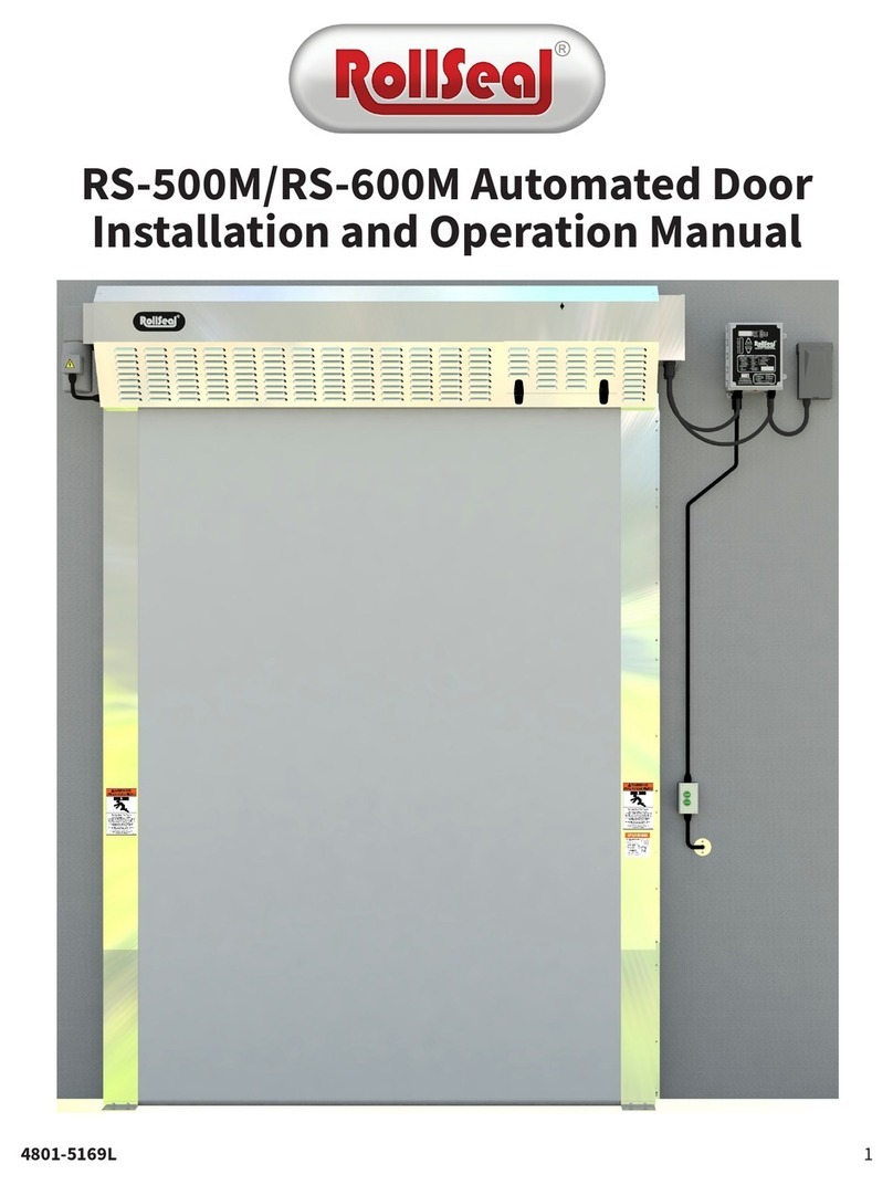
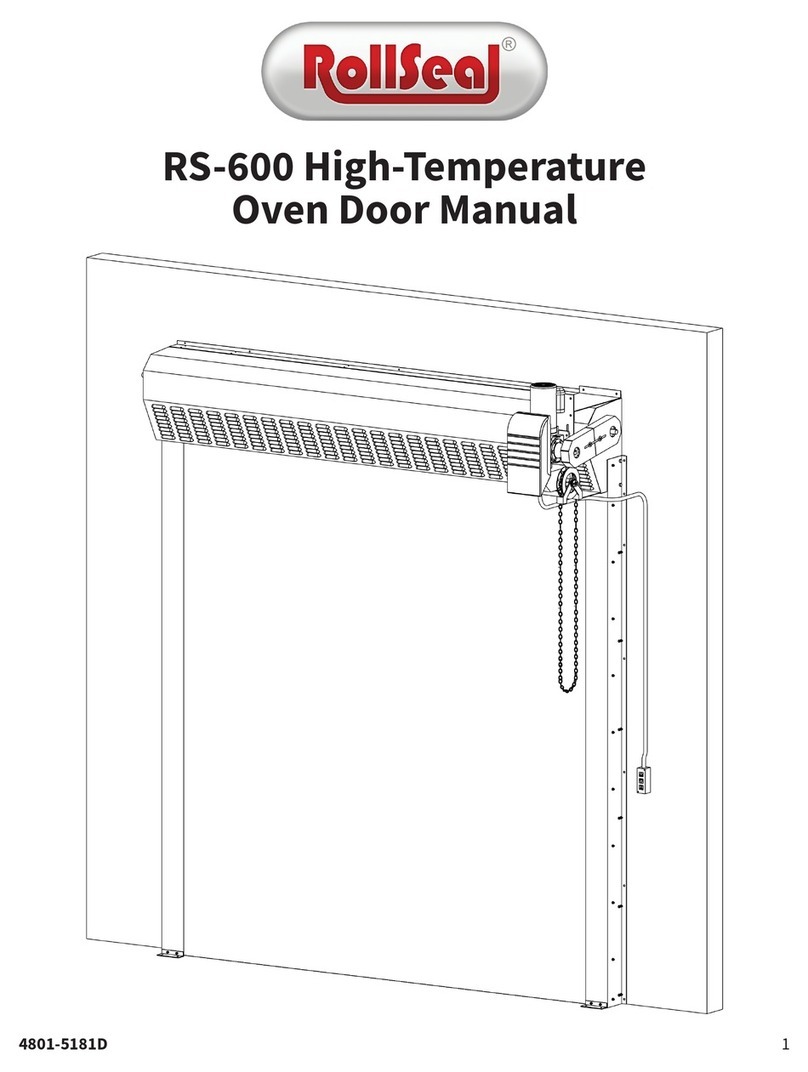
RS-500 WIC, RS-500M, and RS-600M Door Training Guide
NOTICE: If you encounter any issues that cannot be resolved using the information in this document, contact
RollSeal at 1-888-765-5732.
Section 1: Comparison of RS-500 Walk-In Cooler (WIC) Door and RS-500M/RS-600M Door
Section 2: Controller Enclosure Comparison

4802-7536C 2 15 November 2021
RS-500 WIC, RS-500M, and RS-600M Door Training Guide
Section 3: Door Wiring Diagrams
3.1: RS-500 WIC Door

4802-7536C 3 15 November 2021
RS-500 WIC, RS-500M, and RS-600M Door Training Guide
3.2: RS-500M/RS-600M Door

4802-7536C 4 15 November 2021
RS-500 WIC, RS-500M, and RS-600M Door Training Guide
Section 3: Jog Mode
Jog Mode bypasses all switches and safeties, allowing the operator to manually control the position of the door using the Up
and Down arrow buttons beside the Mode button (not the Open/Close switch on the Smart Controller). Press the Up and Down
arrows simultaneously for [5] seconds; the word “JOG” will be displayed. The door can be opened and closed and will not be
affected by the Home limit switch or the safety beam while Jog Mode is active. Watch the door carefully as it approaches the
fully open and fully closed positions.
Press and hold the arrows simultaneously for [5] seconds to disengage Jog Mode. The controller will return to normal operating
mode and the display will show the Actual Position. The controller will not know the door’s exact position so it will display a
series of [3] horizontal bars. Upon the next command, the door will slowly proceed to the fully open position to reset its
memory.
Section 4: Display Indicator
Assumed Position Indication: When the controller is first turned on, this will alternate with the Actual Position reading,
indicating the controller has assumed the current position of the door. When the control button is pressed, the controller will
open at full speed to the open limit of the door. The door will then proceed to the Home switch to verify the position reading
and return to the Open limit position. This verifies the door was not manually adjusted while power was removed from the
controller.

4802-7536C 5 15 November 2021
RS-500 WIC, RS-500M, and RS-600M Door Training Guide
Section 5: Program Parameters
Parameter
Definition
Default Value
P1
Close Time Delay (Seconds)
20
P3
Deceleration Range
0
P4
Warning Output Function
0 – Door Movement/About to Close
1 – Sequential Interlock
2 – Passive Interlock
3 – Door Open Indication
4 – Door Closed Indication
P7
Refresh Door Limits
25
P10
Service Cycle Reset
No
0 – No
1 – Yes
P11
Service Reminder (Cycles x 100)
240
P12
Input Status
-
P20
Open Input Function
0 (Timed Open)
P21
Input Switch Response
0 (Momentary)
P22 (RS-500 WIC Door Only)
Auxiliary Safety Response
1 (Enabled)
P23
Encoder Operation
0 (2 Channels)
P24
CMS Output Function
0
P25
CMS On-Time
15 (If P24=0)
P26
CMS Off-Time
10 (If P24=0)
PS1
Setup Door Limits
-
PS2
Set Open Limit
-
PS3
Set Close Limit
-
Section 6: Setting Limits
PS1 – Change Program Limits:This can be set to Yes or No. To change the Open Limit (PS2) or Closed Limit (PS3), set PS1 to Yes,
then press the Mode button. To exit programming mode, set PS1 to No and press the Mode button.
PS2 – Set Open Limit:When the Mode button is pressed after PS1 has been set, the door will open to the Home switch
position, then proceed toward the Open limit. Use the Up and Down arrows to set the door to a new Open limit, then press the
Mode button to proceed to the next parameter.
PS3 – Set Close Limit: When the Mode button is pressed after the Open limit has been set, the door will close to the current
setting of the Closed limit. Use the Up and Down arrows to set the new Closed limit, then press the Mode button to exit
programming mode and resume displaying the Actual Position.

4802-7536C 6 15 November 2021
RS-500 WIC, RS-500M, and RS-600M Door Training Guide
Section 7: Error Codes and Recommended Actions
RS-500 WIC/WIF Door
Code Condition
Switch LED
Error Code
Panel
Movement
Problem Area Recommended Action(s)
EO1
Opening; Home Switch Tripped
HM
-
Home Switch
Ensure harness connectors are secure and
sensor/switch is not tripped.
EC1
Closing; Home Switch Tripped
HM
-
EO8
Opening; Encoder Fault
FE
-
Encoder Count Fault Ensure harness connectors are secure.
EC8
Closing; Encoder Fault
FE
-
EO16
Opening; Memory Fault
FE
-
Memory Fault
Reset controller.
EC16
Closing; Memory Fault
FE
-
EO32
Opening; Major Fault
FE
-
Major Fault
EC32
Closing; Major Fault
FE
-
EOF1 Opening Fault FE
None
Drive or Brake
Ensure drive is not overloaded.
Up
Encoder
Ensure harness connectors are secure.
Down
Encoder
Reverse panel on pipe.
ECF1 Closing Fault FE
None
Drive or Brake
Ensure drive has not overloaded.
Up
Encoder
Reverse panel on pipe.
Down
Encoder
Ensure harness connectors are secure.
EOF2 Opening; Direction Fault FE
Down
Drive
Reverse [2] phases to motor.
None
Drive or Brake
Ensure drive has not overloaded.
ECF2 Closing; Direction Fault FE
Up
Drive
Reverse [2] phases to motor.
None Brake
Ensure tension pipes are not caught in
head unit.
Down
Encoder
Reverse signal wires.
EOF3
Opening; Motor Stall Fault
FE
-
Motor Stall Fault
-
ECF3
Closing; Motor Stall Fault
FE
-
-
EOF4
Opening; Over Speed Fault
FE
-
Over Speed Fault
-
ECF4
Closing; Over Speed Fault
FE
-
-
RS-500M/RS-600M Door
Code Condition
Panel
Movement
Problem Area Recommended Action(s)
EO1
Opening; Home Switch Tripped
-
Home Switch Check wiring. Ensure Home switch arm is fully depressed.
EC1
Closing; Home Switch Tripped
-
EO2
Egress Switch Tripped
-
Egress Switch
Check wiring and egress switch.
EC2
-
EO3
-
Manually release brake, then pull panel below Home switch.
EC3
-
EO8
Opening; Encoder Fault
-
Encoder Count Fault Check encoders in junction box on door.
EC8
Closing; Encoder Fault
-
EO16
Opening; Memory Fault
-
Memory Fault
Reset controller.
EC16
Closing; Memory Fault
-
EO32
Opening; Major Fault
-
Major Fault
EC32
Closing; Major Fault
-
EOF1 Opening; Encoder Fault
None Egress Strap
Reset yellow limit mark (white patch) on yellow strap up to gold
buckle located on back side/center of door.
Up
Encoder
Check DC harness. Ensure optics are clean.
None
Drive or Brake
Ensure brake is releasing and drive is not overloaded.
Down
Encoder
Reverse panel on pipe.
ECF1 Closing; Encoder Fault
Up
Encoder
Reverse panel on pipe.
None
Drive or Brake
Ensure brake is releasing and drive is not overloaded.
Down
Encoder
Check DC harness. Ensure optics are clean.
EOF2 Opening; Direction Fault
Down
Drive
Reverse [2] phases to motor.
Up
Encoder
Reverse signal wires.
None
Drive or Brake
Ensure brake is releasing and drive is not overloaded.
ECF2 Closing; Direction Fault
Up
Drive
Reverse [2] phases to motor.
None
Brake
Release brake.
Down
Encoder
Reverse signal wires.
EOF3
Opening; Motor Stall Fault
-
Motor Stall Fault
-
ECF3
Closing; Motor Stall Fault
-
-
EOF4
Opening; Over Speed Fault
-
Over Speed Fault
-
ECF4
Closing; Over Speed Fault
-
-

4802-7536C 7 15 November 2021
RS-500 WIC, RS-500M, and RS-600M Door Training Guide
RS-500/RS-600 Door and RS-500M/RS-600M Door – EOF1/EOF2:
•Place the door in Jog Mode.
oIf the door does not jog:
Open the controller and check the status lights on the drive.
•If any lights are off or red, the drive is defective.
•If the lights are green and amber, proceed to the next step.
Release the brake on the motor.
Return to the controller and determine whether the door will jog.
•If the door jogs, the door assembly brake relay is defective.
•If the door does not jog, contact RollSeal (1-888-765-5732) while remaining at the door.
oIf the door jogs:
Check the connections on the black and gray cable (CPCs at head unit).
•If the issue is not resolved, proceed to the next step.
Open the encoder enclosure and check the wiring to the encoder (orange housing plugged into
the encoder circuit board).
•If the door still does not jog, replace the encoder.
Walk-In Cooler Door – EOF1/EOF2:Follow the codes indicated in Section 8 of this document.
Section 8: Smart Switch Indicator Lights

4802-7536C 8 15 November 2021
RS-500 WIC, RS-500M, and RS-600M Door Training Guide
Error
Switch LED Error Code
Description
Primary Safety
PS
Safety Beam (Emitter and Receiver Near Bottoms of Tracks)
Auxiliary Safety
AS
Aux. Safety Sensor (WIC/WIF – Motion Sensor in Head Unit; RS-500M/600M - Egress Strap)
Leading Edge
LE
Leading Edge Switch (Mechanical Switch in Head Unit)
Home Switch
HS
Home Sensor (Fixed-field Sensor in Head Unit)
Feedback Error
FE
Encoder (Error with Encoder Counting or Door Not Operating)
Open Switch
OP
Open Activation
Close Switch
CL
Close Activation
Stop Switch
ST
Stop Switch (if Present)
NOTICE: Safety beams are the primary safety for both RS-500 WIC doors and RS-500M/RS-600M doors. RS-500 WIC doors use a
FLY sensor as an auxiliary safety. RS-500M/RS-600M doors use an egress strap as an auxiliary safety.
1. If the switch lights up but does not operate when pressed, remove the right track clad and ensure the [5] switch
board nuts are tight.
2. In case of a Home or Leading switch error:
a. Check the switch by hand to ensure its operation is mechanically correct.
b. Ensure all switch arms are in the Down position.
c. Ensure no brackets are bent and the switch arm is contacting the panel.
d. Ensure the Home switch power indicator light is on at all times.
Section 9: Drive Board Diagnostics LEDs
The drive’s condition is indicated by a pair of LEDs (Power [“PWR”] and Status [“ST”]) on the drive board. The LEDs may
remain solid, flash slowly (on one second; off one second), or flash quickly (on 0.25 seconds; off 0.25 seconds).

4802-7536C 9 15 November 2021
RS-500 WIC, RS-500M, and RS-600M Door Training Guide
Door Idle
Power LED
Status LED
Condition
Possible Cause(s)
Off Off Drive is off.
A/C power is not applied.
Drive is defective.
Solid Green
Solid Yellow
Operation is normal.
N/A
Quickly Flashing Red and
Yellow
AC input is under voltage. Input AC is 115VAC or drive jumper is set to 230VAC.
Slowly Flashing Red and
Yellow
AC input is over voltage. Input AC is 230VAC or drive jumper is set to 115VAC.
Solid Red
Current is over load.
Drive is tripped due to current overload.
Flashing Red, Yellow, and
Green
Under voltage or over voltage. Drive is tripped because voltage is out of range.
Door Moving
Power LED
Status LED
Condition
Possible Cause(s)
Solid Green
Slowly Flashing Green
Operation is normal.
N/A
Quickly Flashing Green
Current is over load.
Drive is operating between 120% and 200% of rated load.
Slowly Flashing Red Short Circuit
Two phases may be shorted.
Phase may be shorted to ground.
Gear motor may be defective.
Section 10: Condensation Management System Diagnostics
The general status of the Condensation Management System is indicated by four icons at the bottom of the Smart Switch.
Icon
Status
Cause
Supply
On (Green)
The supply fan is operating normally.
Off
The supply fan is not operating.
Return
On (Green)
The return fan is operating normally.
Off
The return fan is not operating.
Heat
On (Green)
The heating element is operating normally.
Off
The heating element is not operating.
Error
Off
The CMS is operating normally.
On (Red)
The CMS has encountered an error. Check the diagnostic LEDs on the PCB 204.

4802-7536C 10 15 November 2021
RS-500 WIC, RS-500M, and RS-600M Door Training Guide
The LEDs at the top-left corner of the PCB 204 provide greater detail about the status of the Condensation Management
System.
LED
Color
Cause
Power
Green
Input power is being supplied to the PCB 204.
CMS Status: ON
Green
The PCB 204 recognizes that the CMS is operational.
CMS Status: Fail
Red
The PCB 204 has detected an issue with at least one of the CMS’s components.
Return Fan (R): ON
Green
The return fan is running at the designated RPM.
Return Fan (R): Fail
Red
The return fan is not operational.
Supply Fan (L): ON
Green
The supply fan is running at the designated RPM.
Supply Fan (L): FAIL
Red
The supply fan is not operational.
Heat: ON
Green
At least one of the two fans is operational. The heating element should be engaged.
Heat: ++ Green
The CMS is in “boost” configuration and is reacting to a requirement for slightly more heat. The LED will turn
off when the requirement is met.
Heat: Low Diff
Red
The temperature sensors do not read the expected temperature difference.
Heat: Hi Temp
Red
The supply-side temperature sensor has reached the factory-set maximum temperature.
Heat: Amb Diff
Red
This LED is currently unused. It is reserved for future use.
Over Pressure
Red
This LED is currently unused. It is reserved for future use.
This manual suits for next models
2
Table of contents
Other RollSeal Door Opening System manuals
Popular Door Opening System manuals by other brands

Najm Alfarqadain
Najm Alfarqadain M-238 operation instruction

Colcom
Colcom Biloba Unica 100E10 Instruction of Assembly

Yale
Yale UNOplus 3000 quick start guide

Tucker Auto-Mation
Tucker Auto-Mation SW10 installation guide

Sesamo
Sesamo smart PRO operating instructions

GTO/PRO
GTO/PRO EXIT WAND installation manual