Bosch Thermotechnik EU 2 D User manual
2994-00.1/O
EU 2 D
7 719 001 855
6 720 610 070 (99.04) OSW
Die einwandfreie Funktion ist nur
gewährleistet, wenn diese Anleitung
beachtet wird. Wir bitten, diese
Schrift dem Kunden auszuhändi-
gen.
Correct functioning is ensured only
when these instructions are ob-
served. We request that this booklet
be given to the customer.
En korrekt funktion kan kun sikres,
hvis nærværende vejledning over-
holdes. Nærværende materiale skal
udleveres til kunden.
eutsch
Deutsch
English
Dansk

EU 2 D
Deutsch
1 Verwendung................................5
2 Einbau ..........................................6
3 Einstellung...................................7
4 Gangreserve ............................ 11
English
1 Application ............................... 12
2 Installation................................. 13
3 Setting....................................... 14
4 Battery Reserve....................... 18
Dansk
1 Anvendelse ...............................19
2 Montering ..................................20
3 Indstilling ...................................21
4 Gangreserve.............................25

EU 2 D
10 5
E
7
4
3
2
1
ECO j
i
2994-07.3/O
g
b
al
o
k
c
v
1. 2. 3. 4. 5. 6. 7.
CL
ch1 ch2
d
1
MAX
START
234
5
6
7
i
hg f e d c b
jk l a
1. 2. 3. 4. 5. 6. 7.
CL
ch1 ch2
2994-01.1/O
2
EU 2 D
MAX
START
234
5
6
7
1. 2. 3. 4. 5. 6. 7.
CL
ch1 ch2
g
fd
c
a
e
l
h
i
j
k
2994-02.1/O
3
2994-04.2/O
q
e
p
t
ay
x
p
4
5
EU 2 D
Deutsch
. . . . . . . . . . . . . . . . . .
1
Verwendung
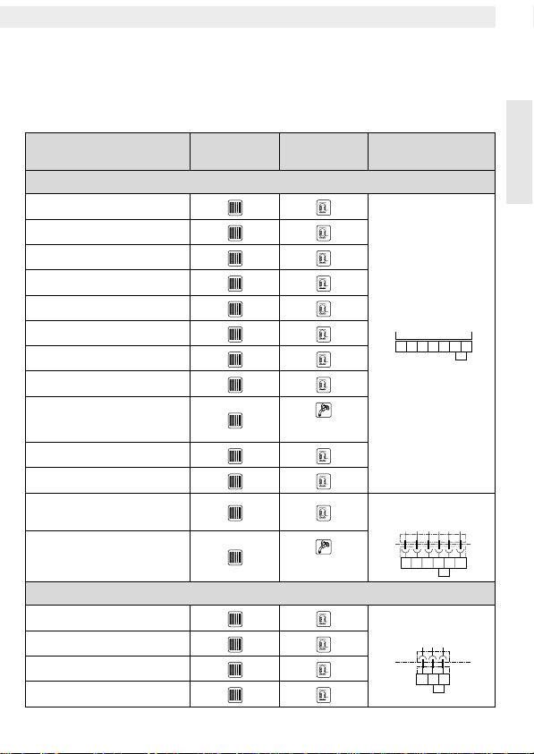
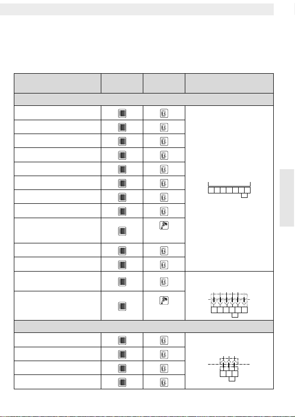
1.1 Kombinationen mit Kesselthermen und Heizkesseln
Heizgerät Kanal 1
(ch 1) Kanal 2
(ch 2) Brücke am
Heizgerät
Kesselthermen
ZR/ZSR 8/11-3/-4...
ZR 18/24-3...
ZWR 18/24-3...
ZR 18/24-4...
ZWR 18/24-4...
ZV 20 A
ZWV 20 A
ZSBR 8-25 A
ZWBR 8-25 A
Komfortschal-
tung
ZWE..-1/-2 A
ZE..-1/-2 A
ZS... mit
Bosch Heatronic
ZW... mit
Bosch Heatronic
Komfortschal-
tung
Heizkessel
KSN...-7 E (EC)
KNS...-7 E (EC)
KNH...-7
KS...-7
DC 24 V
2178945
ST 3
DC 24 V
219748
ST 7
DC 24 V
789

6
EU 2 D
Deutsch
1.2 Kombinationen mit
Heizungsreglern
Die Schaltuhr EU 2 D ist zur Verwen-
dung mit den witterungsgeführten Hei-
zungsreglern TA 210 E / TA 211 E
konzipiert.
Die Verwendung mit dem Raumtem-
peraturregler TR 21 wird nicht emp-
fohlen.
. . . . . . . . . . . . . . . . . .
2
Einbau
Warnung:
Unterbrechen Sie vor
dem Einbau der Schaltuhr die Span-
nungsversorgung zum Heizgerät.
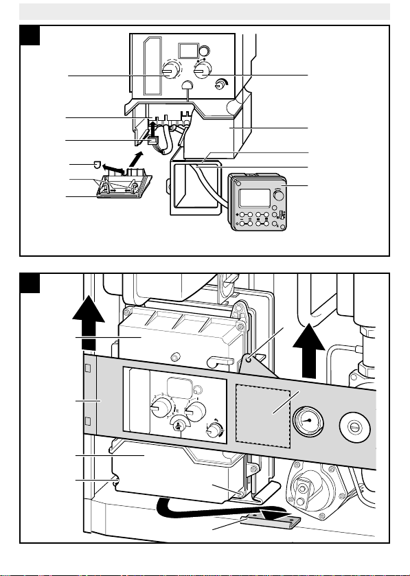
2.1 Kesselthermen mit
Bosch Heatronic (Bild 1)
– Abdeckung des Bedienfelds auf-
klappen, evtl. aushängen.
– Mantelschale abnehmen.
– Lasche (g) drücken und Blinddek-
kel (b) entfernen.
– Dichtring für Spritzwasserschutz
(v) von hinten auf die Schaltuhr (d)
schieben.
– Anschlußkabel (c) durch die Öff-
nung (a) führen und Stecker (i) auf
den Steckkontakt (j) der Hauptlei-
terplatte (ST 5) stecken.
Hinweis:
Verlegen Sie das Kabel
so, daß keine anderen Bauteile be-
schädigt werden.
– Schaltuhr von vorne in die Öffnung
(a) schieben, bis sie einrastet.
– Mantelschale aufsetzen und si-
chern.
– Abdeckung des Bedienfelds (u)
schließen.
2.2 ZR/ZWR/ZSR...-3/-4,
ZE/ZWE..-1/-2 A und
ZV/ZWV 20 A (Bild 2 und 3)
– Mantelschale abnehmen.
– Blinddeckel (b) vom Halteblech
entfernen (nicht bei ZV/ZWV 20
A).
– Schaltuhr von vorne in die Öffnung
(a) schieben, bis sie einrastet.
– Schrauben am Schaltkastendek-
kel (e) lösen und Deckel abneh-
men.
– Laschen (g) zusammendrücken,
Klappe (f) am Schaltkastenboden
entfernen und Kabeldurchführung
(h) herausbrechen.
– Anschlußkabel von hinten zum
Schaltkasten führen und Stecker
auf den Steckkontakt (j) der
Hauptleiterplatte (ST 2) stecken.
– Klappe (f) am Schaltkastenboden
einsetzen.
– Schaltkastendeckel (e) aufsetzen
und verschrauben.
Hinweis:
Entfernen Sie bei Geräten
ZV/ZWV 20 A den Blinddeckel hin-
ter der unteren Klappe der Mantel-
schale.
– Mantelschale aufsetzen und si-
chern.

7
EU 2 D
Deutsch
2.3 ZWBR/ZSBR 8-25 A
(Bild 4 und 5)
– Mantelschale abnehmen.
– Halteschraube (t) der Blende (a)
lösen und Blende nach oben ab-
nehmen.
– Markierte Fläche (y) an der Blende
mit einem Messer ausschneiden.
– Schaltuhr von vorne in die vorge-
sehene Öffnung der Blende (a)
schieben, bis sie einrastet.
– Schaltkasten (q) nach vorne her-
ausziehen und in Serviceposi-
tion X einhängen.
– Schrauben (p) am Schaltkasten-
deckel (e) lösen und Deckel ab-
nehmen.
– Anschlußkabel zum Schaltkasten
führen und Stecker (i) auf den
Steckkontakt (j) der Hauptleiter-
platte (ST 2) stecken.
– Schaltkastendeckel (e) aufsetzen
und verschrauben.
– Schaltkasten (q) einbauen und
Blende mit der Halteschraube (t)
befestigen.
– Mantelschale aufsetzen und si-
chern.
2.4 Heizkessel (Bild 6)
– Abdeckung des Bedienfelds ent-
fernen.
– Blinddeckel (b) entfernen.
– Schaltuhr (d) von vorne in die Öff-
nung (a) schieben, bis sie einra-
stet.
– Schrauben am Schaltkastendek-
kel (e) lösen und Deckel abneh-
men.
– Anschlußkabel (c) von hinten zum
Schaltkasten führen und Stecker
(i) auf den Steckkontakt (j) der
Hauptleiterplatte (ST 2) stecken.
– Schaltkastendeckel (e) aufsetzen
und verschrauben.
– Abdeckung des Bedienfelds befe-
stigen.
. . . . . . . . . . . . . . . . . .
3
Einstellung
Die Schaltuhr verfügt über getrennte
Kanäle für Heizbetrieb (ch 1) und
Speicherladung/Komfortschaltung
(ch 2).
Pro Tag können vier Schaltperioden
(2 Kanäle mit je 2 Schaltperioden)
programmiert werden.
3.1 Grundprogramm
Im Programmspeicher der Schaltuhr
sind werkseitig für die vier Schaltpe-
rioden und alle Wochentage folgen-
de Schaltzeiten gespeichert:
• Beginn Normalbetrieb: 06.00 Uhr
• Beginn Absenkbetrieb: 22.00 Uhr
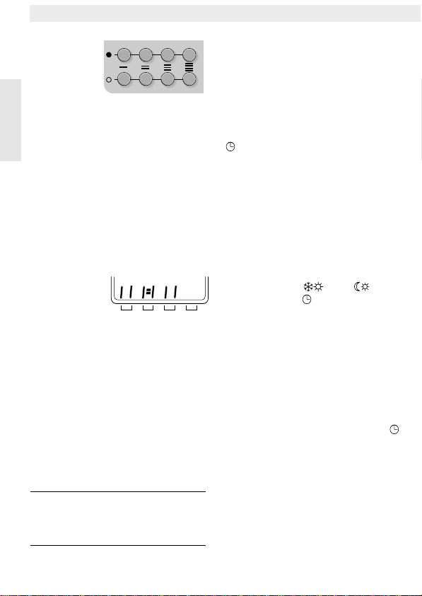
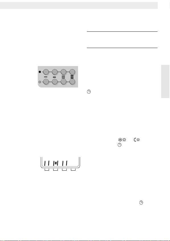
3.2 Bedienelemente und
Anzeigen
3.2.1 Einstelltasten für
Schaltperioden
Die einzelnen Schaltperioden wer-
den mit den paarweise übereinander
angeordneten Tasten
●
(Normalbe-
trieb) und
❍
(Absenkbetrieb) einge-
stellt.
8
EU 2 D
Deutsch
3.2.2 Programmschrittanzeige
• Eine programmierte Schaltperiode
wird mit zwei senkrechten Balken
dargestellt:
Links: Beginn Normalbetrieb
Rechts: Beginn Absenkbetrieb
• Eine aktive Schaltperiode wird
durch Querstriche angezeigt.
• Gelöschte Schaltperioden wer-
den nicht angezeigt.
Beispiel:
• I schon abgearbeitet, II aktiv.
Kanal 1 arbeitet im Normalbetrieb.
• III nicht aktiv, IV nicht program-
miert.
Kanal 2 arbeitet im Absenk-/Frost-
schutzbetrieb.
3.2.3 Löschtaste
Die Löschtaste CL ist versenkt ange-
bracht, um versehentliches Betäti-
gen zu vermeiden.
Hinweis:
Wenn Sie die Löschtaste
drücken, müssen Sie die Schaltuhr
anschließend komplett neu program-
mieren!
• Alle vom Grundprogramm (Heizen
von 06.00 Uhr bis 22.00 Uhr) ab-
weichenden Einstellungen werden
gelöscht.
• Wochentag und Uhrzeit werden
auf Montag, 0.00 Uhr eingestellt.
3.2.4 Betriebsartenschalter
Mögliche Einstellungen:
Automatischer Wechsel zwischen
Normal- und Absenkbetrieb zu den
an der Schaltuhr eingestellten Zei-
ten.
●
Dauernder Heizbetrieb, die
Schaltuhr läuft weiter.
❍
Dauernder Absenkbetrieb, die
Schaltuhr läuft weiter.
Kombination mit TA 210/211 E:
– Betriebsart am Heizungsregler
einstellen:
• TA 210 E: oder
• TA 211 E:
Kanal 1
der Schaltuhr steuert die
automatische Umschaltung zwi-
schen Normal- und Absenkbe-
trieb.
Kanal 2
steuert die Aufheizung
des Warmwasserspeichers bzw.
die Komfortschaltung (bei ZWR...-
3/4 ab FD 761, ZWBR 8-25 A
und ZW.. mit Bosch Heatronic).
– An der Schaltuhr Betriebsart
einstellen, damit alle Reglerfunk-
tionen genutzt werden können.
Absenkbetrieb
Normalbetrieb
I II III IV
Kanal 1 Kanal 2
Schaltperioden
Programm-
schrittanzeige
Schaltperioden I II III IV
Kanal 1 Kanal 2

9
EU 2 D
Deutsch
3.3 Programmieren der
Schaltuhr
Die Reihenfolge zum Programmieren
der Schaltuhr ist fest vorgegeben.
Notwendige Einstellungen:
• Aktueller Wochentag
• Aktuelle Uhrzeit
• Gemeinsames Wochenprogramm
Zusätzliche Einstellungen:
• Individuelle Tagesprogramme
3.3.1 Erst-/Neu-Programmierung
– Löschtaste CL (rg) mit einem dün-
nen Stift drücken.
Alle vom Grundprogramm (Heizen
von 06.00 Uhr bis 22.00 Uhr) ab-
weichenden Einstellungen werden
gelöscht.
Wochentag und Uhrzeit werden
auf Montag 00.00 Uhr gestellt.
Alle Pfeile
▲
der Wochentage
blinken im Wechsel mit dem Dezi-
malpunkt (Bild 8).
3.3.2 Wochentag einstellen
–
∆
-Taste (ri) drücken und halten.
– Pfeil
▲
mit dem Drehknopf (rf) auf
den aktuellen Tag (1. = Montag,
2. = Dienstag; 3. = Mittwoch,
usw.) stellen.
–
∆
-Taste (ri) loslassen.
Der aktuelle Wochentag wird an-
gezeigt und die Zeit 00.00 blinkt
im Wechsel mit dem Dezimalpunkt
(Bild 9).
3.3.3 Uhrzeit einstellen/korrigie-
ren
– -Taste (rh) drücken und halten.
– Uhrzeit mit dem Drehknopf (rf) ein-
stellen.
– -Taste (rh) loslassen.
Alle Wochentage und die Uhrzeit
(im Beispiel: 17.28) werden ange-
zeigt, der Dezimalpunkt blinkt
(Bild 10).
Hinweis:
Die Uhrzeit kann unabhän-
gig von den anderen Einstellungen
immer geändert werden (z. B. um
von Sommer- auf Winterzeit umzu-
stellen). Die Schaltperioden bleiben
dabei unverändert und müssen nicht
neu eingestellt werden.
3.3.4 Wochenprogramm
einstellen
Das Wochenprogramm legt für alle
Tage die gleichen Schaltperioden
fest.
Unbenutzte Schaltperioden
müssen gelöscht werden!
Als Grundprogramm ist werksseitig
an allen Tagen Heizen von 06.00 Uhr
bis 22.00 Uhr eingestellt.
Grundprogramm ändern:
–
●
-Taste (rd) der Schaltperiode
drücken und halten, die geändert
werden soll.
Die Werkseinstellung 06.00 wird
angezeigt (Bild 11).
– Schaltzeit mit dem Drehknopf (rf)
einstellen.
–
●
-Taste (rd) loslassen.
– Darunterliegende
❍
-Taste (re)
drücken und halten.
Die Werkseinstellung 22.00 wird
angezeigt (Bild 12).

10
EU 2 D
Deutsch
– Schaltzeit mit dem Drehknopf (rf)
einstellen.
Hinweis:
Innerhalb eines Heizkrei-
ses dürfen die Heizzeiten nicht über-
lappen.
Die Zeit läßt sich nicht weiter verstel-
len, wenn die vorherige/nächste
Schaltzeit erreicht ist.
Falls notwendig: Angrenzende
Schaltzeit ändern oder löschen.
–❍-Taste (re) loslassen.
– Falls gewünscht: Weitere Schalt-
perioden ändern.
Beispiel für 2 Schaltperioden
(Kanal 1):
Unbenutzte Schaltperioden
löschen:
–●-Taste (rd) der Schaltperiode
drücken und halten, die gelöscht
werden soll.
– Drehknopf (rf) nach links drehen,
bis die Anzeige vier Striche zeigt
(Bild 13).
–●-Taste (rd) loslassen.
– Vorgang mit der darunterliegen-
den ❍-Taste (re) wiederholen.
Einstellung beenden:
–∆-Taste (ri) drücken und halten.
– Pfeil ▲mit dem Drehknopf (rf) auf
den aktuellen Tag stellen.
Kombination mit TA 213 A/A1
(und NTC-Speicher):
– Kanal 1 der Schaltuhr auf Heizen
von 00.00 Uhr bis 23.59 Uhr ein-
stellen.
Kanal 1 ist während der Heizzeiten
beider Kanäle des TA 213 A/A1
in Betrieb.
3.3.5 Tagesprogramme einstellen
Die Tagesprogramme legen für ein-
zelne Tage (z.B. am Wochenende)
individuelle Schaltperioden in Abwei-
chung vom Wochenprogramm fest.
Unbenutzte Schaltperioden
müssen gelöscht werden!
Hinweis: Sie können das Wochen-
programm nach Eingabe eines Ta-
gesprogramms nicht mehr ändern.
Sie müssen dann alle Programme lö-
schen (Löschtaste CL) und die
Schaltuhr neu programmieren.
–∆-Taste (ri) drücken und halten.
– Pfeil ▲mit dem Drehknopf (rf) auf
den gewünschten Wochentag
(z. B. 7. = Sonntag) stellen.
–●-Taste (rd) der Schaltperiode
drücken und halten, die geändert
werden soll.
Die Schaltzeit des Wochenpro-
gramms wird angezeigt.
– Schaltzeit mit dem Drehknopf (rf)
einstellen.
–●-Taste (rd) loslassen.
– Darunterliegende ❍-Taste (re)
drücken und halten.
Die Schaltzeit des Wochenpro-
gramms wird angezeigt.
6 121824
°C
t

11
EU 2 D
Deutsch
– Schaltzeit mit dem Drehknopf (rf)
einstellen.
–❍-Taste (re) loslassen.
– Falls gewünscht: Weitere Schalt-
perioden ändern.
Unbenutzte Schaltperioden
löschen:
–●-Taste (rd) der nicht benötigten
Schaltperiode drücken und halten.
– Drehknopf (rf) nach links drehen,
bis die Anzeige vier Striche zeigt
(Bild 13).
–●-Taste (rd) loslassen.
– Vorgang mit der darunterliegen-
den ❍-Taste (re) wiederholen.
Einstellung beenden:
– Zeiteinstelltaste (rh) kurz drücken.
Das Tagesprogramm ist gespei-
chert und der aktuelle Wochentag
wird angezeigt.
Hinweis: Wenn ca. 1 Minute keine
Eingabe erfolgt, springt die Anzeige
automatisch auf den aktuellen Wo-
chentag zurück.
3.4 Abfragen der Einstellungen
Gespeicherte Programme können je-
derzeit abgefragt werden.
–∆-Taste (ri) drücken und halten.
– Pfeil ▲mit dem Drehknopf (rf) auf
den Wochentag stellen, der abge-
fragt werden soll.
Der Wochentag blinkt.
–●-Taste (rd) oder ❍-Taste (re) der
Schaltperiode drücken, die abge-
fragt werden soll.
Die programmierte Zeit wird ange-
zeigt.
Abfrage beenden:
– -Taste (rh) kurz drücken.
Der aktuelle Wochentag wird ange-
zeigt.
. . . . . . . . . . . . . . . . . .
4Gangreserve
Die Gangreserve beträgt nach min-
destens dreitägigem Betrieb an der
Stromversorgung ca. 16 Stunden.
Während dieser Zeit bleiben die Ein-
stellungen erhalten.
Hinweis: Trennen Sie die Schaltuhr
nicht für längere Zeit vom Stromnetz.
Tiefentladungen verkürzen die Le-
bensdauer der Uhr.
– Heizung nur zu Servicearbeiten
abschalten.
Bei unterbrochener Stromversor-
gung (z. B. Wartungsarbeiten
oder Stromausfall) erlischt die An-
zeige.
Wenn die Heizung außer Betrieb
genommen werden soll:
– Grenztemperatur für automatische
Heizungsabschaltung am Hei-
zungsregler TA 210 E / TA 211 E
ändern.
oder
– Betriebsartenschalter am Heizge-
rät auf „I“ stellen.

12
EU 2 D
English
. . . . . . . . . . . . . . . . . .
1
Application
1.1 Combinations with Heating Boilers
Appliances Channel 1
(ch 1) Channel 2
(ch 2)
Connections
on the
appliance
Heating boilers
ZR/ZSR 8/11-3/-4...
ZR 18/24-3...
ZWR 18/24-3...
ZR 18/24-4...
ZWR 18/24-4...
ZV 20 A
ZWV 20 A
ZSBR 8-25 A
ZWBR 8-25 A
Comfort mode
ZWE..-1/-2 A
ZE..-1/-2 A
ZS... with
Bosch Heatronic
ZW... with
Bosch Heatronic
Comfort mode
Heating boiler
KSN...-7 E (EC)
KNS...-7 E (EC)
KNH...-7
KS...-7
DC 24 V
2178945
ST 3
DC 24 V
219748
ST 7
DC 24 V
789

13
EU 2 D
English
1.2 Combinations with
Heating Controls
The EU 2 D timer is designed for use
with TA 210 E / TA 211 E weather
controlled heating controls.
Usage with the TR 21 room temper-
ature regulator is not recommended.
. . . . . . . . . . . . . . . . . .
2
Installation
Warning:
Disconnect the power
supply to the appliance unit before
installing the timer.
2.1 Appliances with
Bosch Heatronic (Fig. 1)
– Swing open the cover of the con-
trol panel or remove, if necessary.
– Remove the casing shell.
– Press the tab (g) and remove the
dummy panel (b).
– Slide the sealing ring for splash
water protection (v) from the rear
onto the timer (d).
– Lead the connection cable (c)
through the opening (a) and con-
nect the plug (i) to the contacts (j)
of the main circuit board (ST 5).
Note:
Route the cable so that no
other parts are damaged.
– Push the timer from the front into
the opening (a) until it clicks.
– Replace the casing shell and se-
cure.
– Close the cover of the control pan-
el (u).
2.2 ZR/ZWR/ZSR...-3/-4,
ZE/ZWE..-1/-2 A and
ZV/ZWV 20 A (Fig. 2 and 3)
– Remove the casing shell.
– Remove the dummy panel (b) from
the sheet metal facia (not for
ZV/ZWV 20 A).
– Puch the timer from the front into
the opening (a) until it clicks.
– Unscrew the screws on the switch
box cover (e) and remove the cov-
er.
– Press the tabs (g) together, re-
move the flap (f) on the bottom of
the switch box and break out the
cable feed-through (h).
– Route the connection cable from
the rear to the switch box and con-
nect the plug to the contacts (j) of
the main circuit board (ST 2).
– Insert the flap (f) on the bottom of
the switch box.
– Replace the switch box cover (e)
and screw on.
Note:
For the ZV/ZWV 20 A units,
remove the dummy panel behind the
lower flap of the casing shell.
– Replace the casing shell and se-
cure.

14
EU 2 D
English
2.3 ZWBR/ZSBR 8-25 A
(Fig. 4 and 5)
– Remove casing shell.
– Unscrew the holding screw (t) of
the panel (a) and remove the panel
in the upward direction.
– Cut out the marked surface (y) on
the panel with a knife.
– Push the timer from the front into
the opening in the panel (a) until it
clicks.
– Pull out the switch box (q) to the
front and hook in the service posi-
tion X.
– Unscrew the screws (p) on the
switch box cover (e) and remove
the cover.
– Route the connection cable to the
switch box and connect the plug
(i) to the contacts (j)) of the main
circuit board (ST 2).
– Replace the switch box cover (e)
and screw on.
– Reinstall the switch box (q) and at-
tach the panel with the holding
screw (t).
– Replace the casing shell and se-
cure.
2.4 Heating Boilers (Fig. 6)
– Remove the cover of the control
panel.
– Remove the dummy panel (b).
– Push the timer (d) from the front
into the opening (a) until it clicks.
– Unscrew the screws of the switch
box cover (e) and remove the cov-
er.
– Route the connection cable (c)
from the rear to the switch box and
connect the plug (i) to the con-
tacts (j) on the main circuit board
(ST 2).
– Replace the switch box cover (e)
and screw on.
– Attach the cover of the control
panel.
. . . . . . . . . . . . . . . . . .
3
Setting
The timer has separate channels for
heating operation (ch 1) and water
heating/comfort mode operation
(ch 2).
Four switching periods (2 channels
with 2 switching periods each) can
be programmed per day.
3.1 Basic Program
The timer has a „built-in“ basic pro-
gram for all days. For all four switch-
ing periods this is:
• Start of normal operation:
06.00 hrs.
• Start of reduced operation:
22.00 hrs.
15
EU 2 D
English
3.2 Operating Elements
and Indicators
3.2.1 Setting Buttons for the
Switching Periods
Each switching period is set with
buttons arranged in pairs with the
●
(normal operation) buttons above
and the
❍
(reduced operation) be-
low.
3.2.2 Program Step Display
• A programmed switching period is
indicated with two vertical bars:
Left: Start of normal operation
Right: Start of reduced operation
• An active switching period is indi-
cated with horizontal lines.
• Deleted switching periods are not
displayed.
Example:
• Period I already completed, II ac-
tive.
Channel 1 operates in normal
mode.
• Period III not active, IV not pro-
grammed.
Channel 2 operates in re-
duced/frost protection mode.
3.2.3 Clear Button
The clear button CL is recessed to
prevent unintentional operation.
Note:
When the clear button is
pressed, the switching timer must
then be completely reprogrammed!
• All settings are reset to the basic
program (heating from 06.00 to
22.00 hrs).
• Day of the week and time are set
to Monday, 00.00 hrs.
3.2.4 Operating Mode Switch
Possible settings:
Timed operation.
●
Continuous normal operation, the
timer continues to run.
❍
Continuous reduced operation,
the timer continues to run.
In combination with
TA 210/211 E:
– Set the operating mode on the
heating regulator:
• TA 210 E: or
• TA 211 E:
Channel 1
of the switching timer
controls the automatic switch-over
between normal and reduced op-
eration.
Channel 2
controls the heating of
the warm water storage or opera-
tion in the comfort mode
(for ZWR...-3/4 as of FD 761,
ZWBR 8-25 A and ZW.. with
Bosch Heatronic).
– Set the operating mode on the
switching timer so that all regula-
tor functions can be used.
Reduced
operation
Normal
operation
I II III IV
Channel 1 Channel 2
Switching periods
I II III IV
Channel 1 Channel 2
Program step
display
Switching periods

16
EU 2 D
English
3.3 Programming the
Switching Times
The sequence for the programming
of the switching times is fixed.
Necessary settings:
• Current weekday
• Current time
• Common weekly program
Additional settings:
• Individual daily programs
3.3.1 First/Re-Programming
– Press the clear button CL (rg) with
a thin object.
All settings that deviate from the
basic program (heating from
06.00 to 22.00 hrs.) are deleted.
The weekday and the time are set
to Monday 00.00 hrs.
All arrows
▲
of the weekdays blink
alternately with the decimal point
(Fig. 8).
3.3.2 Weekday Setting
– Press and hold the
∆
button (ri).
– Set the day arrow
▲
with the knob
(rf) to the current day (1. = Mon-
day, 2. = Tuesday, 3. = Wednes-
day, etc.).
– Release the
∆
button (ri).
The current weekday is displayed
and the time 00.00 blinks alter-
nately with the decimal point
(Fig. 9).
3.3.3 Setting/Correcting
the Time
– Press and hold the button (rh).
– Set the time of day with the knob
(rf).
– Release the button (rh).
All weekdays and the time (in the
example: 17.28) are displayed and
the decimal point blinks (Fig. 10).
Note:
The time can always be
changed independently of the other
settings (e. g., to change from sum-
mer to winter time). The switching
periods remain unchanged and do
not need to be reprogrammed.
3.3.4 Setting the Weekly
Program
The weekly program sets the same
switching periods for all days of the
week.
Unused switching periods
must be deleted!
The basic program set for all days at
the factory is for heating from 06.00
to 22.00 hrs.
Changing the basic program:
– Press and hold the
●
button (rd) of
the switching period that is to be
changed.
The factory setting of 06.00 is dis-
played (Fig. 11).
– Set the switching time with the
knob (rf).
– Release the
●
button (rd).
– Press and hold the
❍
button (re)
located directly below.
The factory setting of 22.00 is dis-
played (Fig. 12).

17
EU 2 D
English
– Set the switching time with the
knob (rf).
Note:
Within a heating circuit
(ch 1/ch 2), the heating periods
must not overlap.
Change or delete overlapping
switching times.
– Release the
❍button (re).
– Change other switching periods in
the same way if desired.
Example for two switching
periods (Channel 1):
Deleting unused switching
periods:
– Press and hold the ●button (rd) of
the switching period that is to be
deleted.
– Turn the knob (rf) to the left until
the display shows four lines
(Fig. 13).
– Release the ●button (rd).
– Repeat the process for the ❍ but-
ton (re) located directly below.
Completing the setting:
– Press and hold the ∆button (ri).
– Set the ▲ arrow with the knob (rf)
to the current day.
In Combination with the
TA 213 A/A1 (and NTC Storage):
– Set channel 1 of the timer to heat-
ing from 00.00 to 23.59 hrs.
Channel 1 is in operation during
the heating time of both channels
of the TA 213 A/A1.
3.3.5 Setting the Daily Program
The daily program sets switching pe-
riods for single days (e.g., the week-
end) that deviate from the weekly
program. Unused switching peri-
ods must be deleted!
Note: After the entry of a daily pro-
gram, the weekly program can no
longer be changed.
All programs must then be deleted
(clear button CL) and the switching
timer reprogrammed.
– Press and hold the ∆button (ri).
– Set the arrow ▲with the knob (rf)
to the desired weekday (e. g., 7. =
Sunday).
– Press and hold the ●button (rd) of
the switching period that is to be
changed.
The switching time of the weekly
program is displayed.
– Set the switching time with the
knob (rf).
– Release the ●button (rd).
– Press and hold the ❍button (re)
located directly below.
The switching time of the weekly
program is displayed.
– Set the switching time with the
knob (rf).
6 121824
°C
t

18
EU 2 D
English
– Release the ❍button (re).
– Change other switching periods in
the same way if required.
Deleting unused switching
periods:
– Press and hold the ●button (rd) of
the switching period that is not
necessary.
– Turn the knob (rf) to the left until
the display shows four lines
(Fig. 13).
– Release the ●button (rd).
– Repeat the process for the ❍but-
ton (re) located directly below.
Completing the setting:
– Briefly press the time setting but-
ton (rh).
The daily program is stored and the
current weekday is displayed.
Note: When no entry is made for ap-
prox. one minute, the display chang-
es automatically back to the current
weekday.
3.4 Checking the Settings
Stored programs can be checked at
any time.
– Press and hold the ∆button (ri).
– Set the ▲arrow with the knob (rf)
to the weekday that is to be
checked.
The weekday blinks.
– Press the ●button (rd) or the ❍
button (re) of the switching period
that is to be checked.
The programmed time is dis-
played.
Completing the check:
– Briefly press the button (rh).
The current weekday is displayed.
. . . . . . . . . . . . . . . . . .
4Battery Reserve
The battery reserve, after at least
three days of charging while con-
nected to the power supply is ap-
prox. 16 hours. During this time the
settings are retained.
Note: Do not disconnect the timer
for long periods from the power
mains. Deep discharging shortens
the service life of the timer.
– Switch off the heater only for serv-
ice work.
For interrupted power supply (e.
g., maintenance work or power
failure), the display extinguishes.
When the boiler is to be put out
of operation, perform one of the
following:
– Change the limiting temperature
for automatic heater switch-off on
the heater regulator TA 210 E / TA
211 E.
or
– Set the operating mode switch on
the appliance to „I“.
19
EU 2 D
Dansk
. . . . . . . . . . . . . . . . . .
1
Anvendelse
1.1 Kombinationer med centralgaskedler og kedler
Opvarmningsapparat Kanal 1
(ch 1) Kanal 2
(ch 2) Forbindelse på
opvarmningsapparat
Centralgaskedler
ZR/ZSR 8/11-3/-4...
ZR 18/24-3...
ZWR 18/24-3...
ZR 18/24-4...
ZWR 18/24-4...
ZV 20 A
ZWV 20 A
ZSBR 8-25 A
ZWBR 8-25 A
Komfortkob-
ling
ZWE..-1/-2 A
ZE..-1/-2 A
ZS... med
Bosch Heatronic
ZW... med
Bosch Heatronic
Komfortkob-
ling
Kedler
KSN...-7 E (EC)
KNS...-7 E (EC)
KNH...-7
KS...-7
DC 24 V
2178945
ST 3
DC 24 V
219748
ST 7
DC 24 V
789

20
EU 2 D
Dansk
1.2 Kombinationer med
varmeregulatorer
Kontakturet EU 2 D anvendes i for-
bindelse med de vejrkompenserende
varmeregulatorer fra TA 210 E /
TA 211 E.
Det kan ikke anbefales at anvende
rumtemperaturregulatoren TR 21.
. . . . . . . . . . . . . . . . . .
2
Montering
Advarsel:
Afbryd spændingen til
kedlen, før kontakturet monteres.
2.1 Centralgaskedler med
Bosch Heatronic (Fig. 1)
– Klap dækpladen på betjeningsfel-
tet op eller tag den af.
– Tag beskyttelsespladen af.
– Tryk på snippen (g) og fjern blind-
låget (b).
– Skub pakringen til stænkvandsbe-
skyttelse (v) fast på kontakturet (d)
bagfra.
– Før tilslutningskablet (c) gennem
hullet (a) og anbring stikket (i) i
stikkontakten (i) på hovedprintpla-
den (ST 5).
OBS:
Anbring kablet på en sådan
måde, at andre dele ikke beskadiges.
– Skub kontakturet ind i hullet (a)
forfra, indtil det falder på plads.
– Anbring beskyttelsespladen igen.
– Luk dækpladen til betjeningsfel-
tet (u).
2.2 ZR/ZWR/ZSR...-3/-4,
ZE/ZWE..-1/-2 A og
ZV/ZWV 20 A (Fig. 2 og 3)
– Tag beskyttelsespladen af.
– Fjern blindlåget (b) fra holdepla-
den (ikke ved ZV/ZWV 20 A).
– Skub kontakturet ind i hullet (a)
forfra, indtil det falder på plads.
– Løsne skruerne på kontaktskabets
låg (e) og tag låget af.
– Tryk snipperne (g) sammen, fjern
klappen (f) fra kontaktskabets
bund og bræk igennem kabelgen-
nenmføringen (h).
– Før tilslutningskablet hen til kon-
taktskabet bagfra og anbring stik-
ket i stikkontakten (j) på hoved-
printpladen (ST 2).
– Anbring klappen (f) i kontaktska-
bets bund.
– Sæt låget på kontaktskabet (e) og
skru det fast.
OBS:
Ved modellerne ZV/ZWV 20 A
fjernes blindlåget bagved den neder-
ste klap på beskyttelsespladen.
– Anbring beskyttelsespladen igen.
This manual suits for next models
1
Table of contents
Languages:
Other Bosch Thermotechnik Thermostat manuals


Popular Thermostat manuals by other brands

Immergas
Immergas SMARTECH PLUS EXPANSION KIT manual

Honeywell
Honeywell FocusPRO TH5000 Series operating manual

Honeywell
Honeywell WebStat T7350 installation instructions

blossom-ic
blossom-ic HERADIRECT+ Assembly instructions

Genebre
Genebre 3930K manual

Johnson Controls
Johnson Controls Hx3 S1-THXU430W User's information manual


