Bosch Rexroth LU 2 User manual

Assembly instructions
3 842 358 814/2017-01
Replaces: 2016-10
ENGLISH
LU 2
Automatic lubrication unit
3 842 543 482
3 842 543 483
3 842 543 484
3 842 543 485
3 842 543 486
3 842 543 487
ENGLISH
358814_2017_01_EN.indd 1 16.01.2017 13:38:18

2/54
Bosch Rexroth AG, MIT: LU 2, 3 842 358 814/2017-01
The data specified only serve to describe the product. The information provided in the instructions on how to use the supplied product
should only be considered application examples and suggestions. Catalog information is not binding. The information given does not
release the user from the obligation of own judgment and verification. Our products are subject to a natural process of wear and aging.
© This document, as well as the data, specifications and other information set forth in it, are the exclusive property of Bosch Rexroth
AG. It may not be reproduced or given to third parties without its consent.
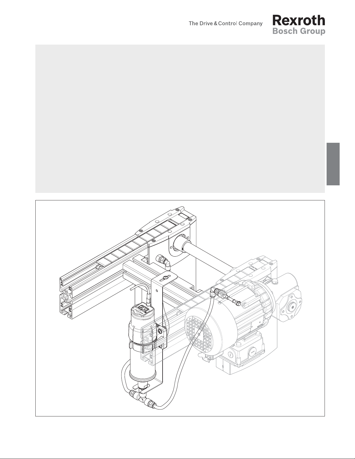
An example configuration is shown on the title page. The delivered product may thus vary from the illustration.
The original assembly instructions were generated in German.
DE Die vorliegende Montageanleitung ist in den hier angebenen Sprachen verfügbar. Weitere Sprachen auf Anfrage.
Als gedruckte Version (print) oder als PDF-Datei (media) zum Download aus dem Medienverzeichnis:
www.boschrexroth.com/medienverzeichnis
Geben Sie in die Suchmaske (oben rechts, unter „Suche“) 3 842 358 814 ein, dann klicken Sie auf „fSuche“.
EN These assembly instructions are available in the languages indicated here. Other languages on request.
They come in a hard copy (print) or a PDF file (media) that can be downloaded at:
www.boschrexroth.com/mediadirectory
Enter 3 842 358 814 in the search mask (at the top right, under “Search”), then click “fSearch”.
FR Les présentes instructions de montage sont disponibles dans les langues spécifiées ici. Autres langues sur demande.
En version imprimée (print) ou en version PDF (media) téléchargeable sur le répertoire multimédia :
www.boschrexroth.com/mediadirectory
Saisissez 3 842 358 814 (en haut à droite, sous « Search »), puis cliquez sur « fSearch ».
IT Le presenti istruzioni di montaggio sono disponibili nelle lingue seguenti. Altre lingue su richiesta.
Scaricabile come versione stampata (print) o come file PDF (media) dal Media Directory:
www.boschrexroth.com/mediadirectory
Digitare il codice 3 842 358 814 nel campo di ricerca “Search” (in alto a destra), quindi fare clic su “fSearch”.
ES Las presentes instrucciones de montaje están disponibles en los idiomas indicados. Hay más idiomas a petición.
Las instrucciones están disponibles como versión impresa (print) o como archivo PDF (media) para descargar del archivo de
medios: www.boschrexroth.com/mediadirectory
En el buscador (en la parte superior derecha, donde pone "Search") introduzca 3 842 358 814, a continuación haga clic en
"fSearch".
PT-
BR
Este manual de montagem está disponível nos idiomas especificados aqui. Outros idiomas mediante pedido.
Como versão impressa (impressão) ou como arquivo PDF (mídia) para download do índice de mídias:
www.boschrexroth.com/mediadirectory
Entre na máscara de pesquisa (canto superior direito, em «Search») 3 842 358 814 e clique em «fSearch».
ZH 本安装说明书有这里给出的语言版本。有印刷版本 (print) 或者电子版 PDF 文件 (media) 供使用,电子版文件可在下列的公司网站媒体网
页上下载: www.boschrexroth.com/mediadirectory
1. 在搜索窗口 (右上角,“Search”窗口) 内输入编号 3 842 546 292。2. 点击“fSearch”。
CS Tento návod k montáži je k dispozici ve zde uvedených jazycích. Jako tištěná verze (print) nebo jako soubor PDF (media) je ke
stažení z adresáře médií: www.boschrexroth.com/mediadirectory
1. Zadejte do vyhledávací obrazovky (nahoře vpravo, pod „Search“) MTCS 358 814. 2. Klikněte na „fSearch“.
PL Dana instrukcja montażu jest dostpna w podanych tutaj językach. W postaci wydrukowanej lub w wersji pdf (media) do
pobrania ze strony: www.boschrexroth.com/mediadirectory
1. Do wyszukiwarki wpisać (w prawym górnym rogu „Search“) MTPL 358 814 . 2. KKliknać „fSearch“
HU A jelen szerelési utasítás az itt megadott nyelveken áll rendelkezésre. További nyelvek rendelésre. A nyomtatott (print) változat
vagy a PDF-fájl (media) letölthető a médiakönyvtárból: www.boschrexroth.com/mediadirectory
Írja be a keresőmezőbe (fent jobbra a „Search“alatt) MTHU 358 814, majd kattintson a „fSearch“gombra.
3 842 358 814 print media LU 2 Automatische Schmiereinheit DE Deutsch
3 842 358 814 print media LU 2 Automatic lubrication unit EN English
3 842 358 814 print media LU 2 Unité de lubrifi cation automatique FR Français
3 842 358 814 print media LU 2 Unità di lubrifi cazione automatica IT Italiano
3 842 358 814 print media LU 2 Unidad de lubricación automática ES Español
3 842 358 814 print media LU 2 Unidade de lubrifi cação automática PT Português
3 842 546 292 print media LU 2 自动润滑单元 ZH 中文
MTCS 358 814 media LU 2 Automatická mazací jednotka CS Česky
MTPL 358 814 media LU 2 Zespół automatycznego smarowania PL Polski
MTHU 358 814 media LU 2 Automatikus kenőegység HU Magyar
358814_2017_01_EN.indd 2 16.01.2017 13:38:18

3 842 358 814/2017-01, MIT: LU 2, Bosch Rexroth AG
3/54Contents
1 About this document 5
1.1 Scope of document 5
1.2 Required and supplementary documentation 5
1.3 Presentation of information 5
1.3.1 Safety instructions 5
1.3.2 Symbols 6
1.3.3 Designations 7
2 Safety instructions 7
2.1 About this chapter 7
2.2 Intended use 7
2.3 Improper use 8
2.4 Qualification 8
2.5 General safety information 8
2.6 Product-specific safety instructions 9
2.7 Personal protective equipment 10
2.8 Owner obligations 10
3 General information regarding damage to property and the product 10
4 Scope of delivery 11
4.1 Delivery state 11
4.2 Accessories 11
5 About this product 11
5.1 Performance description 11
5.1.1 Automatic lubrication unit LU 2 use 11
5.1.2 Automatic lubrication unit LU 2 design 11
5.2 Product description 12
5.3 Identification of the product 13
6 Function 14
6.1 TIME mode 14
6.1.1 Setting the delivery volume in the TIME operating mode 15
6.1.2 Display of the remaining delivery period 16
6.2 PULSE mode 17
6.2.1 Setting the delivery volume in the PULSE operating mode 18
6.3 Required delivery volume 20
6.3.1 Flat top chain: every 1000 h 20
6.3.2 Flat top chain: every 2000 h 20
6.3.3 Accumulation roller chain: every 1000 h 21
6.3.4 Accumulation roller chain: every 2000 h 21
6.3.5 Vplus accumulation roller chain: every 1000 h 22
6.3.6 Vplus accumulation roller chain: every 2000 h 22
6.4 Special delivery PURGE 23
6.5 PIN number 24
6.6 Counter pressure monitoring 24
6.7 Low temperature monitoring 24
6.8 Indicator elements and signal outputs 25
6.8.1 LED indicators and display 25
6.8.2 Signal outputs 25
Contents
ENGLISH
358814_2017_01_EN.indd 3 16.01.2017 13:38:18

4/54
Bosch Rexroth AG, MIT: LU 2, 3 842 358 814/2017-01
6.8.3 Cable break detection 25
7 Transport and storage 26
7.1 Transporting the product 26
7.2 Storing the product 26
8 Installation 27
8.1 Unpacking 27
8.2 Installation requirements 27
8.2.1 Installation position 27
8.2.2 Mounting with T-bolts 27
8.3 Required tools 27
8.4 Symbols used 28
8.5 Installing the product 29
8.5.1 Install the holder for the lubrication unit LU 2 29
8.5.2 Install support bracket and connector set in the holder 30
8.5.3 Install lubrication unit LU 2 31
8.5.4 Install adapter Set AS 2/C-100, -250 33
8.5.5 Install adapter Set AS 2/C-400, AS 2/C-700 34
8.5.6 Install adapter Set AS 2/R-300, AS 2/R-700 35
8.5.7 Install adapter Set AS 2/R-1200, AS 2/R-2200 36
8.5.8 Install adapter Set AS 2/R-1200, AS 2/R-2200 37
8.6 Make the electrical connection to the product 38
8.6.1 PLC programming suggestions for evaluating the signal outputs 39
9 Start-up 41
9.1 First-time operation 41
9.1.1 Short description commissioning 42
9.2 Re-commissioning after a standstill period 42
10 Operation 43
10.1 Notices regarding operation 43
10.1.1 Wear 43
10.1.2 Steps for reducing wear 43
10.1.3 Environmental influences 43
11 Maintenance and repair 44
11.1 Cleaning and care 45
11.2 Inspection 45
11.3 Maintenance 45
11.4 Replacement of worn parts 45
11.4.1 Exchange oil container LC 2 46
11.4.2 Exchange battery LU 2 48
11.4.3 Replacement parts 48
12 Shutdown 49
13 Disassembly and replacement 49
13.1 Preparing the product for storage/further use 49
14 Disposal 50
15 Upgrading and modification 50
16 Troubleshooting 51
17 Technical data 52
17.1 Storage period 52
17.2 Ambient conditions 53
358814_2017_01_EN.indd 4 16.01.2017 13:38:18

About this document 5/54
3 842 358 814/2017-01, MIT: LU 2, Bosch Rexroth AG
1 About this document
1.1 Scope of document
This documentation applies to the following products:
• Lubrication unit LU 2, 3 842 543 482
• Adapter Set AS 2/C-100, -250, 3 842 543 483
• Adapter Set AS 2/C-400, -700, 3 842 543 484
• Adapter Set AS 2/R-300, -700, 3 842 543 485
• Adapter Set AS 2/R-1200, -2200, 3 842 543 486
• Adapter Set AS 2/R-V, 3 842 543 487
• Oil container LC 2, 3 842 543 469
This manual is intended for engineers, operators, service engineers and
system end users.
This document contains important information to install, transport, commission,
operate, use, maintain, and dismantle the product safely and correctly and
on simple troubleshooting.
fRead this manual completely, especially chapter 2 “Safety” and Chapter 3,
“General notes for property damage and product damage” before working with
the product.
1.2 Required and supplementary documentation
fOnly operate when you are in possession of the documentation marked with the
book symbol and you have understood and observed this.
Table 1: Required and supplementary documentation
Title Document number Document type
Safety-related information for staff 3 842 527 147
MTparts 3 842 529 770 Spare part list available on CD
1.3 Presentation of information
In order for you to work with your product quickly and safely using this documentation,
safety symbols, terms and abbreviations are used in a uniform manner.
These are explained in the following sections to help you understand them better.
1.3.1 Safety instructions
In this documentation, safety instructions are given in chapter 2.6 “Specific product
precautions” and Chapter 3 “General notes on property and product damage”, and
before a course of action or a required action, in which there is a risk of personal
injury or property damage. Be sure to observe all safety precautions.
ENGLISH
358814_2017_01_EN.indd 5 16.01.2017 13:38:18

6/54 About this document
Bosch Rexroth AG, MIT: LU 2, 3 842 358 814/2017-01
Safety instructions are set out as follows:
SIGNAL WORD
Type and source of danger!
Consequences of non-compliance
fMeasures to prevent hazards
f…
•Warning sign: points out the hazard
•Signal word: identifies the severity of the hazard
•Type and source of danger: indicates the type and source of the danger
•Consequences: describes what occurs when failing to take precautions
•Precaution: states how the hazard can be avoided
Table 2: Hazard classes according to ANSI Z535.6-2006
Warning sign, signal word Meaning
DANGER Indicates a hazardous situation which will result in death or
serious injury if not avoided.
WARNING Indicates a hazardous situation which can result in death or
serious injury if not avoided.
CAUTION Indicates a hazardous situation which can result in minor or
moderate injury if not avoided.
NOTICE Damage to property: The product or the environment
could be damaged.
1.3.2 Symbols
The following symbols indicate notices which are not safety-relevant but make the layout
of the document more clear.
Table 3: Meaning of the symbols
Symbol Meaning
If this information is not observed, the product cannot be used and/or
operated optimally.
fSingle, non-related actions
1.
2.
3.
Numbered instructions:
The numbers indicate that the actions must be carried out one after the
other.
358814_2017_01_EN.indd 6 16.01.2017 13:38:18

Safety instructions 7/54
3 842 358 814/2017-01, MIT: LU 2, Bosch Rexroth AG
1.3.3 Designations
In this documentation, the following designations are used:
Table 4: Designations
Designation Meaning
LU 2 Automatic lubrication unit from the Rexroth transfer system TS 2plus
LC 2 Oil container for the automatic lubrication unit LU 2
AS 2/… Adapter set for the automatic lubrication unit LU 2
2 Safety instructions
2.1 About this chapter
This product has been manufactured using state-of-the-art technology.
Nevertheless, there is a risk of personal injury and property damage if you do not
observe this chapter and the safety instructions in this document.
fRead this manual thoroughly and completely before you start working with
the product.
fKeep these instructions accessible to all users at all times.
fAlways include the operating instructions when transferring this product
to third parties.
2.2 Intended use
The product is an incomplete machine.
This product may be used for the following:
• for installation in a Rexroth transfer system TS 2plus for lubrication of the transport
chain.
• for lubrication of 1 belt section BS 2/… or 1 section unit SE 2/…in the drive station.
• for operation with 2 equal lubrication pins.
• For the environmental conditions see page 53.
The product is strictly intended for professional use and not for private use.
The intended use also implies that you have read and understood this
documentation, especially chapter 2 “Safety”.
ENGLISH
358814_2017_01_EN.indd 7 16.01.2017 13:38:18

8/54 Safety instructions
Bosch Rexroth AG, MIT: LU 2, 3 842 358 814/2017-01
2.3 Improper use
Any use other than that described in Chapter “Intended use” is considered improper
and is not permitted.
Bosch Rexroth AG is not liable for any damages resulting from improper use.
The user is solely responsible for the consequences of improper use.
The following also fall under the category of improper use:
• Using the product for lubrication of more than 1 belt section BS 2/… or
1 section unit SE 2/… .
• Using the product with other than the specified lubricant.
• Using the product with non-specified accessories.
• Using the product with lubrication lines unequal length.
• Using the product with unequal lubrication pins.
• Using the product without ensuring that it is in the correct position.
• Private use.
2.4 Qualification
The activities described in this documentation require basic knowledge of
mechanical, electrical and pneumatic systems, as well as knowledge of the
appropriate technical terms. Additional knowledge in dealing with a hoist and the
associated slings are required for transport and handling of the product.
To ensure safe use, these activities may only be performed by a specialist or
personnel under the direction of a specialist.
“Specialist” refers to a person who can recognize potential hazards and take
appropriate safety measures due to their technical training, knowledge and
experience, and understanding of the relevant regulations pertaining to the work
being performed. Qualified personnel must comply with the relevant technical
regulations and have the necessary expertise.
Bosch Rexroth offers training to support activities in specific areas.
You can find an overview of the training content online at
http://www.boschrexroth.de/didactic
2.5 General safety information
• Observe the regulations for accident prevention and environmental protection.
• Observe the safety rules and regulations of the country in which the product is
used/applied.
• Only use Rexroth products that are in good working order.
• Follow all instructions printed on the product.
• Persons who assemble, operate, disassemble, or maintain Rexroth products must
not consume any alcohol, drugs, or pharmaceuticals that may affect their
reaction time.
• Use only original accessories and spare parts from Rexroth to prevent hazards to
persons due to improper spare parts.
• Observe the technical data and ambient conditions listed in the product
documentation.
358814_2017_01_EN.indd 8 16.01.2017 13:38:18

Safety instructions 9/54
3 842 358 814/2017-01, MIT: LU 2, Bosch Rexroth AG
• You may operate the product only when it was found that the final product (such as
a machine or system), in which the Rexroth products are installed, is in accordance
with the respective national provisions, safety regulations and the standards for the
application.
2.6 Product-specific safety instructions
• Do not modify or alter the product.
• Do not expose the product to unacceptable mechanical loads under any
circumstances. Never use the product as a handle or step. Do not place objects on it.
• Always secure the product against tipping.
• Observe the transport information on the packaging.
• Check the product for visible damage during transport.
• Lay the cables and lines so that they cannot be damaged and no one can trip
over them.
• Make sure the relevant system component is not under pressure or voltage before
assembling the product or when connecting and disconnecting plugs.
• Secure the system component from being switched on.
• Before start-up, make sure that all seals and caps for the screwed connections are
correctly installed and undamaged to prevent fluids and debris from infiltrating
the product.
• Allow the product to acclimate for a few hours before start-up, otherwise
condensation may form in the housing.
• Make sure that all electrical connections are either used or covered.
• Check the security requirements according to DIN EN 619.
• Start up the product only if it is installed completely.
• Make sure that all safety equipment belonging to the product is present,
has been installed properly, and is fully functional. Do not displace,
bypass, or disable the safety equipment.
• Do not reach into moving parts.
• Check the product for malfunctions.
• Make sure only authorized personnel perform the following within the scope of
intended use:
– Start or operate the system, or intervene in its normal functioning.
– Operate adjustment devices on components.
• Only allow persons who are authorized by the owner to access the product's direct
operating area. This also applies when the product is standing still.
• Make sure that:
– There are no obstacles preventing access to the EMERGENCY STOP control units.
– All delivery points, workstations and passages remain freely accessible.
• Do not use EMERGENCY STOP control units for routine stops.
• Regularly check the proper functioning of the EMERGENCY STOP control units.
• In the event of an error or other irregularities, after an EMERGENCY STOP turn the
product off and secure it against restarting.
• Do not reach into moving parts.
• An idle system is not a safe system, as stored energy can be released
unintentionally or through improper maintenance procedures.
General
During transport
During assembly
During start-up
During operation
ENGLISH
358814_2017_01_EN.indd 9 16.01.2017 13:38:18

10/54 General information regarding damage to property and the product
Bosch Rexroth AG, MIT: LU 2, 3 842 358 814/2017-01
• After an EMERGENCY STOP or a malfunction, only switch on the system once
the cause of the fault has been determined and the error resolved.
• Make sure that there are no obstacles blocking access to maintenance and
inspection points.
• Perform the prescribed maintenance work at the intervals prescribed in
chapter 10.3 Maintenance.
• Make sure that no lines, connectors, or components are disconnected as long
as the system is under pressure and voltage. Secure the system against being
switched back on.
• Dispose of the product in accordance with the currently applicable national
regulations in your country.
2.7 Personal protective equipment
• Appropriate protective clothing is to be worn when handling the product
(e.g. safety shoes, close-fitting clothing, a hair net for long, loose hair).
As owner or operator, you are responsible for appropriate protective equipment
when using the product.
All personal protective equipment must be intact.
2.8 Owner obligations
• Before first use or re-commissioning of a conveyor system, run a risk assessment
in accordance with DIN EN ISO 12100.
• Before initial commissioning ensure that there are no protruding or sharp-edged
parts that may endanger personnel working or moving in the area.
• Provide safety-related instructions to the operating personnel before first use or
re-commissioning, and then in regular intervals.
3 General information regarding damage to
property and the product
The warranty only applies to the delivered configuration.
• The warranty is void in case of faulty installation, commissioning and operation, as
well as improper use and / or improper handling.
• Avoid the penetration of detergent into the system.
• Never use solvents or aggressive detergents.
• Do not use a high-pressure cleaner for cleaning.
EMERGENCY STOP, fault
During maintenance and
repair
During disposal
During cleaning
358814_2017_01_EN.indd 10 16.01.2017 13:38:18

Scope of delivery 11/54
3 842 358 814/2017-01, MIT: LU 2, Bosch Rexroth AG
4 Scope of delivery
The following is included in delivery:
• 1 Automatic lubrication unit LU 2
• Assembly instructions for “Automatic lubrication unit LU 2”
4.1 Delivery state
Unassembled in parts.
4.2 Accessories
(not included in the delivery)
• Oil container LC 2, 3 842 543 469
• Adapter Set AS 2/C-100, -250, 3 842 543 483
• Adapter Set AS 2/C-400, -700, 3 842 543 484
• Adapter Set AS 2/R-300, -700, 3 842 543 485
• Adapter Set AS 2/R-1200, -2200, 3 842 543 486
• Adapter Set AS 2/R-V, 3 842 543 487
5 About this product
5.1 Performance description
5.1.1 Automatic lubrication unit LU 2 use
• Lubrication of concealed running transport chains in the transfer system TS 2plus.
• for lubrication of 1 belt section BS 2/… or 1 section unit SE 2/…in the drive station.
• Exclusively for operation with 2 equal lubrication pins.
5.1.2 Automatic lubrication unit LU 2 design
• The automatic lubrication unit LU 2 consists of the components
– Lubrication unit LU 2, 3 842 543 482
– Oil container LC 2, 3 842 543 469
– Adapter Set AS 2/C-100, -250, 3 842 543 483 1)
– Adapter Set AS 2/C-400, -700, 3 842 543 484 1)
– Adapter Set AS 2/R-300, -700, 3 842 543 485 1)
– Adapter Set AS 2/R-1200, -2200, 3 842 543 486 1)
– Adapter Set AS 2/R-V, 3 842 543 487 1)
1) Not part of the delivery, please order separately.
ENGLISH
358814_2017_01_EN.indd 11 16.01.2017 13:38:18

12/54 About this product
Bosch Rexroth AG, MIT: LU 2, 3 842 358 814/2017-01
5.2 Product description
Fig. 1:
A
G
H
I
J
K
2x
2x
2x
2x
2x
C
E
F
B
358 814-01
D
Product description
A: Lubrication unit LU 2
B:Drive
C: Oil container LC 2 1)
D:Holder, complete with
assembly accessories
E:Support bracket
F: Connection set
G: Adapter Set
AS 2/C-100, -250 1)
H: Adapter Set
AS 2/C-400, -700 1)
I: Adapter Set
AS 2/R-300, -700 1)
J: Adapter Set
AS 2/R-1200, -2200 1)
K: Adapter Set
AS 2/R-V 1)
1) Not part of the delivery,
please order separately.
358814_2017_01_EN.indd 12 16.01.2017 13:38:18

About this product 13/54
3 842 358 814/2017-01, MIT: LU 2, Bosch Rexroth AG
5.3 Identification of the product
Fig. 2: Name plate
B
Typschild
....... ..........
.........
.................
........
A
C
A: Part no.
(Order number)
B: Designation
C: Design and
dimensions
ENGLISH
358814_2017_01_EN.indd 13 16.01.2017 13:38:18

14/54 Function
Bosch Rexroth AG, MIT: LU 2, 3 842 358 814/2017-01
6 Function
The lubrication unit LU 2 has two operating modes:
• TIME mode
• PULSE mode
A special delivery volume (PURGE) can also be triggered and the operation of
the lubrication unit can also be disabled using a 2-digit PIN number.
The device is equipped with counter pressure and lower temperature monitoring.
Device settings are retained even after a power failure by the use of an integrated
backup battery.
6.1 TIME mode
A metering period (per month, 1 to 12 months) can be entered in the TIME mode.
During this metering period metered volumes of lubricant are delivered at fixed,
regular intervals (interval period 't [h:mm]). The volume of metered lubricant
delivered is determined by the metering period, the interval period and the entered
oil container LC 2.
Only in TIME mode: At the initial startup the drive runs for approximately 8 sec
after the supply voltage is connected to prime the lubrication unit.
The operation then starts with the first interval time. When the interval time
has expired the metered volume is delivered.
• The operating mode, the entered delivery period, the entered oil container LC 2
(ÖLC250) and the metered volume to be delivered per 100 hours are shown on
the display.
• Metered lubricant deliveries are only executed when the supply voltage is connected.
• Metered lubricant deliveries not executed because of a fault are automatically
rescheduled at half the interval time.
Table 5: The delivery volume is determined by the delivery duration and interval
Delivery period
Month
Interval time
't [h:mm]
Delivery volume [cm³/100 h]
with oil container LC 2 (= LC250)
11:30 34
23:00 17
34.36 11
46:06 8.5
57:36 6.8
69:06 5.7
710:36 4.8
812:12 4.2
913:42 3.8
10 15:12 3.4
11 16:42 3.1
12 18:12 2.8
358 814-25
Please note:
(1 cm³ |0.9 g lubricant)
358814_2017_01_EN.indd 14 16.01.2017 13:38:18

Function 15/54
3 842 358 814/2017-01, MIT: LU 2, Bosch Rexroth AG
6.1.1 Setting the delivery volume in the TIME operating mode
The mode of operation, the oil container used LC 2 (ÖLC250) and the delivery
period is entered via the display using the SET button.
The delivery period must be entered in relation to the required delivery volume,
interval period and the oil tank used LC 2 (ÖLC250) (see Table 5 on page 14).
• The input is executed with the power supply disconnected. The power supply for
the electronics comes from an integrated backup battery.
• The oil container LC 2 must be installed on the drive prior to the setting
(see page 31).
In the as delivered condition the display is on the left.
1. Press and hold the SET button (> 5 s), until the modes TIME and PULSE flash
in the display.
2. Press 1x the SET button.
The display switches to the TIME mode (TIME flashes).
After about 3 seconds, the display switches to the selection of the oil container.
3. Press SET button 1x ¨LC60
Press SET button 2x ¨LC120
Press SET button 3x ¨LC250 (= LC 2)
The selected oil container flashes in the display (here LC250).
After about 3 seconds, the display switches to the entry of the metered lubricant
delivery period.
4. To enter the delivery period press the SET button repeatedly.
Months 1...12 can be scrolled through.
The delivery period entered flashes in the display.
Approximately 3 seconds after the entry (inactive SET button) the setting mode
for the delivery period is terminated.
The operating mode, the entered delivery period, the entered oil container LC 2
(ÖLC250) and the metered volume to be delivered per 100 hours are shown on
the display.
358 814-27
358 814-28
358 814-29
358 814-30
358 814-31
358 814-32
358 814-33
358 814-34
ENGLISH
358814_2017_01_EN.indd 15 16.01.2017 13:38:18

16/54 Function
Bosch Rexroth AG, MIT: LU 2, 3 842 358 814/2017-01
5. Turn on the power to the lubrication unit.
Make the electrical connection to the product see page 38.
The plug icon (cable break detection, see page 25) appears in the display and
the arrow icon dflashes in the display. The drive LEDs flash green at
5 s intervals.
The initial start of the operation begins about 8 s after the supply voltage with
the interval time.
6.1.2 Display of the remaining delivery period
During operation, the remaining delivery period can be shown in the display.
fPress and hold the SET button during operation for > 1 s (flashing arrow
icon din the display).
The display shows the remaining delivery time in hours.
>999h hours appears in the display where the remaining delivery time is
equal or greater than 1000 hours.
358 814-34
358 814-37
358814_2017_01_EN.indd 16 16.01.2017 13:38:18

Function 17/54
3 842 358 814/2017-01, MIT: LU 2, Bosch Rexroth AG
6.2 PULSE mode
In PULSE mode delivery volume can be entered in defined steps.
According to the volume of the oil container entered LC 2 (= LC250),
a certain number of lubricant deliveries follow, with the appropriate
delivery volume.
• The operating mode, the oil container used LC 2 (LC250), and the required delivery
volume per pulse (delivery) are entered via the display using the SET button.
• If the number of remaining pulses (deliveries) is 100 or greater, the following
indicator appears in the display >99 (Field in the table with a gray background).
• The delivery is carried out once with supply voltage (rising flank).
• The supply voltage must be present at least as long enough for the delivery
process to be completed (min. 2 minutes).
• Before the following delivery the supply voltage must be shut down for > 1 s.
• The signaling/display of system states and errors is only possible when the
supply voltage is present.
358 814-26
ENGLISH
358814_2017_01_EN.indd 17 16.01.2017 13:38:18

18/54 Function
Bosch Rexroth AG, MIT: LU 2, 3 842 358 814/2017-01
Table 6: Number of deliveries is dependent on the volume of the metered lubricant
to be delivered and the oil container LC 2
Delivery volume
[cm³/pulse]
Number of pulses (delivery) per oil container
LC 2 (ÖLC250)
0.1 2500
0.2 1250
0.3 833
0.4 625
0.5 500
0.6 417
0.7 357
0.8 313
0.9 278
1.0 250
1.2 208
1.4 179
1.6 156
1.8 139
2.0 125
2.2 114
2.4 104
2.6 96
2.8 89
3.0 83
3.5 71
4.0 62
4.5 56
5.0 50
5.5 45
6.0 42
6.5 38
7.0 36
7.5 33
8.0 31
8.5 29
9.0 28
9.5 26
6.2.1 Setting the delivery volume in the PULSE operating mode
The operating mode, the oil container used LC 2 (ÖLC250) and the required
delivery volume per pulse (delivery) are entered via the display using the SET button.
The number of pulses (deliveries) can be taken from Table 6 on page 18.
Please note:
(1 cm³ |0.9 g lubricant)
358814_2017_01_EN.indd 18 16.01.2017 13:38:18

Function 19/54
3 842 358 814/2017-01, MIT: LU 2, Bosch Rexroth AG
• The input is executed with the supply voltage disconnected.
The power supply for the electronics comes from an integrated backup battery.
• The oil container LC 250 must be installed on the drive prior to the setting
(see page 31).
In the as delivered condition the display is on the left.
1. press and hold the SET button (> 5 s), until the modes TIME and PULSE
flash in the display.
2. Press 2x the SET button.
The display switches to the PULSE mode (PULSE flashes).
After about 3 seconds, the display switches to the selection of the oil container.
3. Press SET button 1x ¨LC60
Press SET button 2x ¨LC120
Press SET button 3x ¨LC250 (= LC 2)
The selected oil container flashes in the display (here LC250).
After about 3 seconds, the display switches to the entry of the metered lubricant
delivery volume.
4. To enter the delivery volume per pulse press the SET repeatedly. The delivery
volume of 0.1...9.5cm³/pulse can be scrolled through in the pre-entered steps.
The delivery volume entered per pulse flashes in the display.
Approximately 3 seconds after the entry (inactive SET button) the setting mode
for the delivery volume is terminated.
The operating mode, the quantity of remaining pulses, the entered oil container
LC 2 (ÖLC250) and the metered volume to be delivered per pulse are shown on
the display.
If the number of remaining pulses is 100 or greater, the following indicator
appears in the display >99.
5. Turn on the power to the lubrication unit.
Make the electrical connection to the product see page 38.
The plug icon (cable break detection, see page 25) appears in the display and
the arrow icon dflashes in the display. The drive LEDs flash green at 5 s intervals.
358 814-27
358 814-28
358 814-39
358 814-40
358 814-41
358 814-42
358 814-43
358 814-44
358 814-44
ENGLISH
358814_2017_01_EN.indd 19 16.01.2017 13:38:18

20/54 Function
Bosch Rexroth AG, MIT: LU 2, 3 842 358 814/2017-01
6.3 Required delivery volume
6.3.1 Flat top chain:
Required delivery volume for 2 - 3 g oil/m chain every 1000 h
Fig. 3:
1)
2)
2019181716151413121110987654321
11
6
1
y [h]
x [m]
358 814-16
Flat top chain: Required delivery volume for 2 - 3 g oil/m chain every 1000 h
6.3.2 Flat top chain:
Required delivery volume for 2 - 3 g oil/m chain every 2000 h
Fig. 4:
1)
2)
2019181716151413121110987654321
11
6
1
y [h]
x [m]
358 814-16
Flat top chain: Required delivery volume for 2 - 3 g oil/m chain every 2000 h
x[m]: Section length
y[h]: Distance between
the discharging
operations
1): Delivery volume
each pulse: 0.26 cm3
2): Delivery volume
each pulse: 0.55 cm3
x[m]: Section length
y[h]: Distance between
the discharging
operations
1): Delivery volume
each pulse: 0.26 cm3
2): Delivery volume
each pulse: 0.55 cm3
358814_2017_01_EN.indd 20 16.01.2017 13:38:18
Table of contents