8
Test and Time Setting
Test and Time Setting
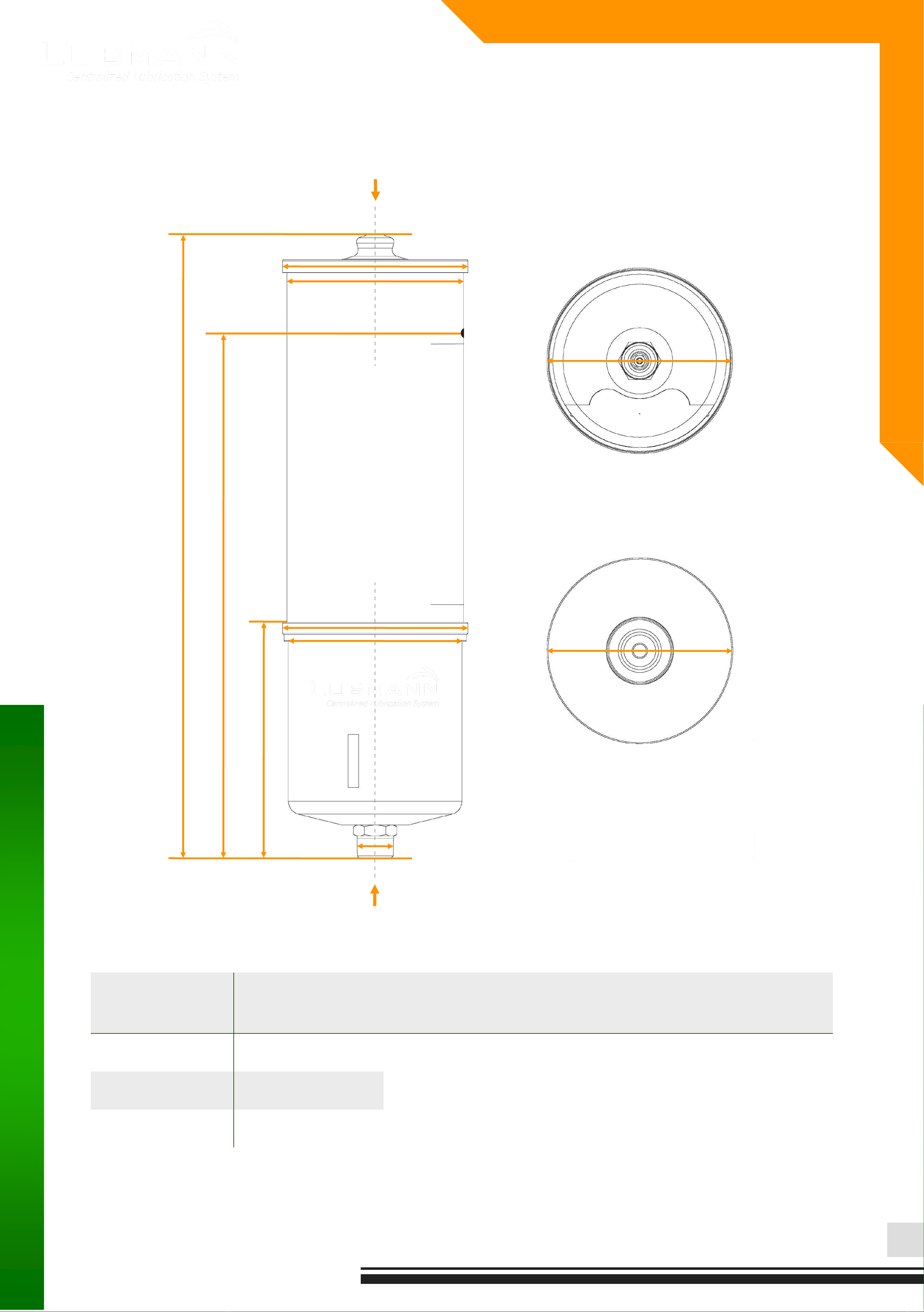
ALP01 Pump
Operation Period Adjustment
To change the preset operation period:
1. Use the magnetic cap vertically close to the Setup EM induction
point to active the setting mode till the preset/default operation
period LED turns on, then move the cap away.
2. Use the magnetic cap close to the induction point again for at
least 3 seconds to adjust the length of the operation period.
3. The light jumps to the next value after removing the cap*.
4. Repeat the step 2 and 3to choose the required length of the
operation period.
5. Move the cap away, let the LED of the required value be lighting
for 5 seconds and flashing once to save the setting.
6. Put the magnetic cap back to the top of the lubricator.
Adjustment of the operation period length finishes.
* The jumping sequence is 1 - 3 - 6 - 12 -24 - 1
The original setting of the operation period length is 6 (6 months)
Test Cycle
Use the magnetic cap close to the Test induction point for at least 3
seconds, then move the cap away. The lubricator starts
immediately a manual greasing cycle (fixed running time as around
20 seconds* and the total greasing volume around 0.6 cm3).
During the running time, use the cap to close the test induction
point again can immediately stop the cycle.
During the test cycle running time, the LED for corresponding
setting of the operation period will continue to flash until the running
cycle ends.
Recommended: After the lubricator is long inactive or the battery
is replaced, start a test greasing cycle to ensure that the lubricator
works in goods position and confirm the current setting of the
operation period.
* The length of the manual running time equals a normal programmed
running time, is around 20 seconds. It can be longed depends on the
working situation and type of lubricant (max. 60 seconds).
Dia. 8.2 Test Greasing
Cycle
Dia. 8.1 Adjustment of
Operation Period Length
About Being Idle
Caution: A function of stopping the lubricator is NOT available in
our standard version. Please take off the battery during a long term
maintenance of the equipment.
Product Manual - ALP01 Single Point Lubricator