Bosch XDK 110 Configuration guide

XDK110: General Information Guide
Document revision 2.0
Document release date 17.08.17
Workbench version 3.0.0
Document number BCDS-XDK110-GUIDE-GENERAL-INFORMATION
Technical reference code(s)
Notes Data in this document is subject to change without notice. Product
photosandpicturesareforillustrationpurposesonlyandmaydifferfrom
the real product’s appearance.
Subject to change without notice
General Information Guide
Cross-Domain Development Kit XDK110
Platform for Application Development
Bosch Connected Devices and Solutions

XDK110 BCDS
© Bosch Connected Devices and Solutions GmbH reserves all rights even in the event of industrial property rights. We reserve all rights of disposal such as
copying and passing on to third parties. BOSCH and the symbol are registered trademarks of Robert Bosch GmbH, Germany.
Note: Specifications within this document are subject to change without notice.
General Information Guide XDK110
!
Page !2
XDK General Information Guide
PLATFORM FOR APPLICATION DEVELOPMENT
Key Features
•All-in-one sensor development kit:
oNo need for component selection and hardware assembly
oNo need for deployment of a real-time operating system
•Drivers for all system components included
•Includes 8 different Micro Electrical-Mechanical Sensors (MEMS)
•WLAN and Bluetooth Low Energy communication technology
•LW-M2M Protocol Stack
•XDK Workbench included as Integrated Development Environment for programming XDK
•Access to the XDK developer community for online technical support, idea discussion,
exchange and more
•Small form factor
•High-level Sensor API for the standard user and powerful low-level API for the power user
•Functional extendibility via the included 26 pin extension port
•2 programmable push buttons
•1 system LED and 3 programmable LEDs
•Debugger port
•CE, FCC and IC certified
General Description
The XDK110 is a wireless sensor device to enable rapid prototyping of sensor based products and
applications for the internet of things (IoT). It thereby allows users a step in-between the first
hardware prototype and series production, or simply as the first compact prototype. The device
was built in a way that Bosch can easily adapt the product for mass production and the users’
unique sensor requirements. The XDK110 creates the opportunity for users to try out more
advanced programming on the device itself to realize a sensor which processes data and reports
events instead of simply transmitting raw data.
The product XDK110 consists of the XDK110 sensor device, comes with a SW development
environment called the XDK Workbench as well as access to the XDK developer community.
XDK110 allows the user the ability to experiment with different ideas, with different sensor
measuring principles, coupled together with different communication technologies. XDK110
thereby allows the user to better understand their end solution requirements, but also their
potential series product before having to invest substantial sums of engineering development
activity.
XDK110 is built using a modular hardware and software platform, meaning that mass production of
variations of XDK is easy, scalable and cost effective for the user when moving forward with their
idea.

XDK110 BCDS
© Bosch Connected Devices and Solutions GmbH reserves all rights even in the event of industrial property rights. We reserve all rights of disposal such as
copying and passing on to third parties. BOSCH and the symbol are registered trademarks of Robert Bosch GmbH, Germany.
Note: Specifications within this document are subject to change without notice.
General Information Guide XDK110
!
Page !3
Table of Contents
KEY FEATURES 2............................................................................................................................
GENERAL DESCRIPTION 2...............................................................................................................
1. GETTING STARTED 5..................................................................................................................
1.1 INTENDED USE 5......................................................................................................................
1.2 HARDWARE OVERVIEW 5..........................................................................................................
1.2.1 MAIN COMPONENTS 5.......................................................................................................
1.2.2 INCLUDED DELIVERIES 5....................................................................................................
1.2.3 TECHNICAL SPECIFICATIONS 6...........................................................................................
1.2.4 XDK DEVICE 6.................................................................................................................
1.2.5 USER INTERFACE: LEDS& BUTTONS 7..............................................................................
1.3 GETTING STARTED 8.................................................................................................................
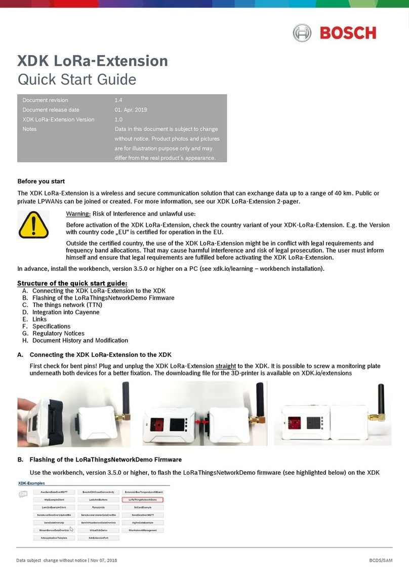
1.3.1 SOFTWARE DOWNLOAD AND INSTALLATION 8......................................................................
1.3.2 CONNECTING XDK110 8...................................................................................................
2. FUNCTIONAL DESCRIPTION 9...................................................................................................
2.1 BLOCK DIAGRAM 9...................................................................................................................
2.2 POWER MANAGEMENT 10.........................................................................................................
2.3 SENSORS 11............................................................................................................................
2.3.1 BMM150: THREE-AXIS GEOMAGNETIC SENSOR 11............................................................
2.3.2 BMA280: THREE-AXIS ACCELERATION SENSOR 12............................................................
2.3.3 BMG160: THREE-AXIS ANGULAR RATE SENSOR 13...........................................................
2.3.5 BME280: ENVIRONMENTAL SENSOR 15............................................................................
2.3.6 AKU340: ACOUSTIC NOISE SENSOR 16............................................................................
2.3.7 MAX44009: AMBIENT LIGHT SENSOR 16...........................................................................
2.4 RADIOS 17...............................................................................................................................
2.4.1 WLAN 17.........................................................................................................................
2.4.2 LOW-ENERGY BLUETOOTH 17...........................................................................................
2.5 SD CARD 17............................................................................................................................
2.6 MICROCONTROLLER 17.............................................................................................................
3. XDK SOFTWARE OVERVIEW – THE XDK WORKBENCH 18...................................................
3.1 POWER CONSUMPTION AND ENERGY MANAGEMENT 18.............................................................
3.1.1 BATTERY STATUS 19.........................................................................................................
3.1.2 SLEEP MANAGEMENT 19...................................................................................................
3.2 XDK WORKBENCH - WELCOME SCREEN 20..............................................................................
3.2.1 HANDS ON& DOCUMENTATION 20.....................................................................................
3.2.2 FEEDBACK 20...................................................................................................................
3.2.3 XDK EXAMPLES - BASICS 21............................................................................................
3.2.4 COMMUNITY FEED 21........................................................................................................
3.3 XDK WORKBENCH – WORKSPACE (XDK VIEW) 21....................................................................
3.3.1 UPDATING XDK WORKBENCH 22.......................................................................................
3.3.2 PROJECT EXPLORER 26....................................................................................................
3.3.3 EDITOR 26........................................................................................................................
3.3.4 CONSOLE 27....................................................................................................................
General Information Guide XDK110
!
Page !3

XDK110 BCDS
© Bosch Connected Devices and Solutions GmbH reserves all rights even in the event of industrial property rights. We reserve all rights of disposal such as
copying and passing on to third parties. BOSCH and the symbol are registered trademarks of Robert Bosch GmbH, Germany.
Note: Specifications within this document are subject to change without notice.
General Information Guide XDK110
!
Page !4
3.4 BUILD SYSTEM 28....................................................................................................................
3.4.1 MAKEFILE 28....................................................................................................................
3.5 OPERATING XDK 31.................................................................................................................
3.5.1 USB PORT 31..................................................................................................................
3.5.2 OPERATION MODES 33......................................................................................................
3.6 FIRMWARE OVER THE AIR (FOTA) 39.......................................................................................
3.6.1 INTRODUCTION 39.............................................................................................................
3.6.2 FOTA CONTAINER 40........................................................................................................
3.6.4 FOTA CONTAINER CREATION 41.......................................................................................
3.6.5 FOTA UPDATE PROCESS 43.............................................................................................
4. INTERFACES 44...........................................................................................................................
4.1 EXTENSION INTERFACE 44........................................................................................................
4.2 CONNECTING EXTERNAL COMPONENTS TO THE XDK 44............................................................
4.2.1 CONNECTING THE “XDK GATEWAY” EXTENSION BOARD 44................................................
4.2.2 CONNECTING YOUR OWN COMPONENTS TO THE XDK GATEWAY BOARD 44.......................
4.2.3 SOFTWARE EXAMPLE 47...................................................................................................
4.2.4 MECHANICAL DESIGN OF EXTENSION BOARDS 48................................................................
4.2.5 ERRATA 48.......................................................................................................................
5. REGULATORY INFORMATION 50...............................................................................................
5.1 ROHS 50.................................................................................................................................
5.2 TELECOMMUNICATION 50..........................................................................................................
5.3 RADIOFREQUENCY RADIATION EXPOSURE AND FURTHER INFORMATION 50..................................
5.4 CERTIFICATION 50....................................................................................................................
6. LEGAL DISCLAIMER 52..............................................................................................................
7. DOCUMENT HISTORY AND MODIFICATION 53.......................................................................
General Information Guide XDK110
!
Page !4

XDK110 BCDS
© Bosch Connected Devices and Solutions GmbH reserves all rights even in the event of industrial property rights. We reserve all rights of disposal such as
copying and passing on to third parties. BOSCH and the symbol are registered trademarks of Robert Bosch GmbH, Germany.
Note: Specifications within this document are subject to change without notice.
General Information Guide XDK110
!
Page !5
1. Getting Started
1.1 Intended Use
The XDK110 Cross-Domain Development Kit is a prototyping platform for Internet of Things (IoT)
use cases. It works with Windows 7 or higher.
1.2 Hardware Overview
1.2.1 Main Components
•MCU: 32-bit microcontroller ARM Cortex M3 EFM32GG390F1024 (Silicon Labs)
•Communication interface
oBluetooth Low Energy
oLow power IEEE 802.11b/g/n WLAN
•Inertial sensors (9DOF)
oAccelerometer: BMA280 (Bosch Sensortec)
oGyroscope: BMG160 (Bosch Sensortec)
oMagnetometer: BMM150 (Bosch Sensortec)
oInertial measurement unit BMI160 (Bosch Sensortec)
•Environmental sensors
oCombined humidity / temperature / air pressure sensor: BME280 (Bosch Sensortec)
oAmbient light: MAX44009 (Maxim Integrated)
oMicrophone for noise detection: AKU340 (Akustica)
•Internal Li-Ion rechargeable battery, 560 mAh capacity
•Integrated antennas
•User interface:
o3 programmable status LEDs
o2 programmable push-buttons
oMicro SD card‑1
oJ-Link debug interface‑2
oInterface for extension board
1.2.2 Included Deliveries
•Device in its housing, with built-in lithium ion rechargeable battery
•“XDK Gateway” extension board for easy access to additional MCU functionality, incl.
connector cable
•Micro USB 2.0 connector cable
•Mounting plate and screws!
Micro SD card not included
1
L-Link debug adapter needed, not included; see JTAG Debug Interface
2
General Information Guide XDK110
!
Page !5

XDK110 BCDS
© Bosch Connected Devices and Solutions GmbH reserves all rights even in the event of industrial property rights. We reserve all rights of disposal such as
copying and passing on to third parties. BOSCH and the symbol are registered trademarks of Robert Bosch GmbH, Germany.
Note: Specifications within this document are subject to change without notice.
General Information Guide XDK110
!
Page !6
1.2.3 Technical Specifications
Table 1: XDK110 Specifications
Please note that full sensor performance might be limited to a more narrow temperature range, and
sensor performance might be decreased when operating outside this corner cases. Refer to the
sensor datasheets for details.
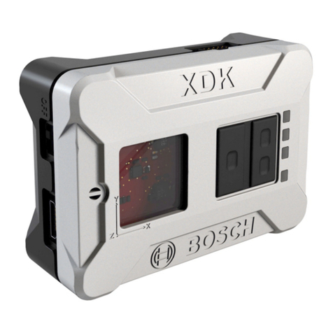
1.2.4 XDK Device
Picture 1: Bosch XDK Device
!
Name
Value
Temperature Range
-20 °C – 60 °C (operating)
0 °C – 45 °C (charging)
Humidity
10 – 90 % r.H., non-condensing
IP Rating
IP 30 (IEC 60529)
Flammability classification
HB (IEC 60695-11-10/-20; CSA C 22.2)
Voltage
5 V DC
Charging Current
500 mA Maximum
Communication (cable)
USB
Wireless LAN
IEEE 802.11 b/g/n
Bluetooth 4.0 low energy
IEEE 802.15.1
General Information Guide XDK110
!
Page !6

XDK110 BCDS
© Bosch Connected Devices and Solutions GmbH reserves all rights even in the event of industrial property rights. We reserve all rights of disposal such as
copying and passing on to third parties. BOSCH and the symbol are registered trademarks of Robert Bosch GmbH, Germany.
Note: Specifications within this document are subject to change without notice.
General Information Guide XDK110
!
Page !7
1.2.5 User Interface: LEDs & Buttons
The XDK has four LEDs to signal the operation mode it is currently in, three of which can be
configured by the user when in application mode. The fourth (green) LED is used to display the
state of the charger chip and cannot be accessed by software.
The following status can be displayed by the green LED:
Table 2: Meaning of the green LED
The following status can be displayed by the red, orange and yellow LED:"
Table 3: Meaning of the programmable LEDs
The XDK110 uses the LED to show the following states:
After the XDK110 has been switched on, a running light demo will start.
Green LED
Hardware Status
On
Battery is charging or charging suspended by thermal loop
Off
Charging done/Recharging after termination/IC disabled
or No valid Input Power/Battery absent
Blinking
Safety timers expired
Red !
LED
Orange
LED
Yellow
LED
Bootloader Mode
Application Mode
On
Off
Off
Active; no USB connection"
or driver not loaded
No function
Off
Off
Off
Inactive
Blinking
On/Off
Off
Active; program invalid,
cannot boot
On
On
Off
Active, USB connection
detected
XDK stopped, "
assertion occurred
On
Blinking
Off
Active; Data is transmitted
No function
On
On
On
Inactive
XDK stopped, "
stack overflow occurred
General Information Guide XDK110
!
Page !7

XDK110 BCDS
© Bosch Connected Devices and Solutions GmbH reserves all rights even in the event of industrial property rights. We reserve all rights of disposal such as
copying and passing on to third parties. BOSCH and the symbol are registered trademarks of Robert Bosch GmbH, Germany.
Note: Specifications within this document are subject to change without notice.
General Information Guide XDK110
!
Page !8
1.3 Getting Started
1.3.1 Software Download and installation
The software for the XDK is available online. You can download the software from http://
www.xdk.bosch-connectivity.com. Go to the download section to get the latest software package
and demos.
Download the software package “XDK Workbench” from the website http://www.xdk.bosch-
connectivity.com and start the installer. The software package contains all necessary components.
Program examples, demos and a toolbox are included.
1.3.2 Connecting XDK110
Connect the USB cable (included in delivery) to the USB connector of your PC and the Mini USB
connector of the XDK.
Note: Functional Limitations:
The device can be impaired or damaged if the power source is inadequate.
• Do not use cables >3 m.
• Use only certified USB power adapters/connectors.
General Information Guide XDK110
!
Page !8

XDK110 BCDS
© Bosch Connected Devices and Solutions GmbH reserves all rights even in the event of industrial property rights. We reserve all rights of disposal such as
copying and passing on to third parties. BOSCH and the symbol are registered trademarks of Robert Bosch GmbH, Germany.
Note: Specifications within this document are subject to change without notice.
General Information Guide XDK110
!
Page !9
2. Functional Description
2.1 Block Diagram
The following Picture 2 shows a simplified block diagram of the XDK110:
Picture 2: Block diagram of XDK110
General Information Guide XDK110
!
Page !9

XDK110 BCDS
© Bosch Connected Devices and Solutions GmbH reserves all rights even in the event of industrial property rights. We reserve all rights of disposal such as
copying and passing on to third parties. BOSCH and the symbol are registered trademarks of Robert Bosch GmbH, Germany.
Note: Specifications within this document are subject to change without notice.
General Information Guide XDK110
!
Page !10
2.2 Power Management
For the easy application in portable applications, the XDK is equipped with a 560mAh Li-Ion
rechargeable battery. While connected to a power source via the Micro USB connector, the battery
will automatically be charged. Charging is indicated by the green LED. The device can be charged
independent of the position of the power switch. The maximum charging current depends on the
charger used.
Table 4: Charger Type and Current
Additional details on these port types are described in the USB Battery Charging Specification, Rev
1.1, 4/15/
Charger Type
Maximum Current
Standard downstream port (SDP):
Typical form found in desktop and laptop computers
100 mA
Charging downstream port (CDP):
Higher current USB port for PCs, laptops, and other
hardware (indicated by a lightning symbol)
500 mA
Dedicated charging port (DCP):
Power sources like wall warts and auto adapters; charging
can occur with no digital communication at all.
500 mA or 100 mA depending on
charger
General Information Guide XDK110
!
Page !10

XDK110 BCDS
© Bosch Connected Devices and Solutions GmbH reserves all rights even in the event of industrial property rights. We reserve all rights of disposal such as
copying and passing on to third parties. BOSCH and the symbol are registered trademarks of Robert Bosch GmbH, Germany.
Note: Specifications within this document are subject to change without notice.
General Information Guide XDK110
!
Page !11
2.3 Sensors
XDK110 is equipped with a multitude of sensors on board, which makes it an ideal tool for
application development for the Internet of Things.
This documentation refers to the datasheets of the sensors for a deeper understanding of the
components. It is, however, vital to understand that sensor performance will be limited by the
application hardware. As an example, the temperature range of most sensors will be -40 to +85 °C
in the datasheet, while the XDK is only specified for a usage between -20 and +60 °C due to
physical and safety limits of the battery. Also, sensor accuracy is generally higher in the sensor
datasheet than it can be expected from the target device, since the assembly process and
mechanical stress of the board influence the performance of any sensor. The absolute maximum
ratings of the key parameters are stated for each sensor. For more details, please refer to the
respective sensor datasheet.
2.3.1 BMM150: Three-Axis Geomagnetic Sensor
The BMM150 is a standalone geomagnetic sensor for consumer market applications. It allows
measurements of the magnetic field in three perpendicular axes. Based on Bosch’s proprietary
FlipCore technology, performance and features of BMM150 are carefully tuned and perfectly match
the demanding requirements of all three-axis mobile applications such as electronic compass,
navigation or augmented reality.
Table 5: BMM150 Key Features
For more information please refer to the datasheet:
http://ae-bst.resource.bosch.com/media/products/dokumente/bmm150/BST-BMM150-
DS001-01.pdf!
Specification
Value
Resolution
0.3 µT
Zero-B Offset
±50 µT
Non-Linearity
<1 % FS
Magnetic Range (typical)
±1300 µT (X;Y-Axis);
±2500 µT (Z-Axis)
Average Current Consumption
170 µA (Low Power Preset);"
500 µA (Normal Mode)
Interrupts
New Data;
Magnetic Threshold High/Low
General Information Guide XDK110
!
Page !11

XDK110 BCDS
© Bosch Connected Devices and Solutions GmbH reserves all rights even in the event of industrial property rights. We reserve all rights of disposal such as
copying and passing on to third parties. BOSCH and the symbol are registered trademarks of Robert Bosch GmbH, Germany.
Note: Specifications within this document are subject to change without notice.
General Information Guide XDK110
!
Page !12
2.3.2 BMA280: Three-Axis Acceleration Sensor
The BMA280 is an advanced, ultra-small, triaxial, low-g acceleration sensor with digital interfaces,
aiming for low-power consumer electronics applications. Featuring 14-bit digital resolution, the
BMA280 allows very low-noise measurement of accelerations in three perpendicular axes and thus
senses tilt, motion, shock and vibration in cellular phones, handhelds, computer peripherals, man-
machine interfaces, virtual reality features and game controllers.
Table 6: BMA280 Key Features
For more information please refer to the datasheet:
http://www.bosch-sensortec.com/en/homepage/products_3/3_axis_sensors/acceleration_sensors/
bma280/bma280!
Specification
Value
Digital Resolution
14 bit
Resolution (in ±2 g range)
0.244 mg
Measurement Ranges (programmable)
±2 g, ±4 g, ±8 g, ±16 g
Sensitivity"
(calibrated)
±2 g: 4096 LSB/g"
±4 g: 2048 LSB/g"
±8 g: 1024 LSB/g"
±16 g: 512 LSB/g
Zero-g Offset"
(typical, over life-time)
±50 mg
Noise Density (typical)
120 µg/√Hz
Bandwidths"
(programmable)
500 Hz ... 8 Hz
Current Consumption"
(full operation)
130 µA (@2 kHz data rate)
General Information Guide XDK110
!
Page !12

XDK110 BCDS
© Bosch Connected Devices and Solutions GmbH reserves all rights even in the event of industrial property rights. We reserve all rights of disposal such as
copying and passing on to third parties. BOSCH and the symbol are registered trademarks of Robert Bosch GmbH, Germany.
Note: Specifications within this document are subject to change without notice.
General Information Guide XDK110
!
Page !13
2.3.3 BMG160: Three-Axis Angular Rate Sensor
The BMG160 is an ultra-small, digital three-axis angular rate sensor with a measurement range up
to 2000 °/s and a digital resolution of 16 bit for consumer electronics applications. The BMG160
allows low-noise measurement of angular rates in three perpendicular axes and is designed for
use in cellular phones, handhelds, computer peripherals, man-machine interfaces, virtual reality
features, remote and game controllers.
Table 7: BMG160 Key Features
For more information please refer to the datasheet:
http://ae-bst.resource.bosch.com/media/products/dokumente/bmg160/BST-BMG160-DS000-09.pdf
Specification
Value
Digital Resolution
16 bit
Measurement Ranges (programmable)
± 125 °/s, ± 250 °/s,"
± 500 °/s, ± 1000 °/s,"
± 2000 °/s
Sensitivity (calibrated)
± 125 °/s: 262.4 LSB/ °/s"
± 250 °/s: 131.2 LSB/ °/s"
± 500 °/s: 65.5 LSB/ °/s"
± 1000 °/s: 32.8 LSB/ °/s"
± 2000 °/s: 16.4 LSB/ °/s
Zero-Rate Offset (typical)
± 1 °/s
Zero-Rate Offset over Temperature
0.015 °/s/K
Noise Density (typical)
0.014 °/s/√Hz
Low-Pass Filter Bandwidths (programmable)
230, 116, 64, 47, 32, 23, 12 Hz
Date Rates (programmable)
2000, 1000, 400, 200, 100 Hz
Current Consumption (full operation)
5.0 mA
Current Consumption (fast power-up)
2.5 mA
General Information Guide XDK110
!
Page !13

XDK110 BCDS
© Bosch Connected Devices and Solutions GmbH reserves all rights even in the event of industrial property rights. We reserve all rights of disposal such as
copying and passing on to third parties. BOSCH and the symbol are registered trademarks of Robert Bosch GmbH, Germany.
Note: Specifications within this document are subject to change without notice.
General Information Guide XDK110
!
Page !14
2.3.4 BMI160: Inertial Measurement Unit
The BMI160 is a small, low-power, low-noise 16-bit inertial measurement unit designed for use in
mobile applications like augmented reality or indoor navigation which require highly accurate, real-
time sensor data. In full operation mode, with both the accelerometer and the gyroscope enabled,
the current consumption is typically 950 µA, enabling always-on applications in battery driven
devices.
Table 8: BMI160 Key Features
For more information please refer to the datasheet:
http://www.bosch-sensortec.com/en/homepage/products_3/6_axis_sensors_2/
inertial_measurement_unit_1/bmi160/bmi160_1
Note: Why two gyroscopes?
As you will have noticed by now, the XDK has two MEMS gyroscopes on board: A stand-alone
BMG160 and another one combined with an accelerometer in the inertial measurement unit
BMI160.
The sensor in the BMI160 is an “open-loop” gyroscope, which results in very low noise and low
power consumption (~1 mA). The BMG160 works in “closed loop”, which results in an excellent
zero-Ωoffset change over temperature (TCO), which can be two orders of magnitude below the
open-loop version. As a result, the power consumption is higher (~5 mA).
We encourage you to try out both sensors, and decide which is best for your application.
Specification
Value
Digital Resolution
Accelerometer (A): 16 bit"
Gyroscope (G): 16 bit
Measurement Ranges"
(programmable)
(A): ± 2 g, ± 4 g, ± 8 g, ± 16 g"
(G): ± 125 °/s, ± 250 °/s, ± 500 °/s,"
± 1000 °/s, ± 2000 °/s
Sensitivity (calibrated)
(A): ±2g: 16384 LSB/g"
±4g: 8192 LSB/g"
±8g: 4096 LSB/g"
±16g: 2048 LSB/g"
(G): ±125 °/s: 262.4 LSB/ °/s"
±250°/s: 131.2 LSB/ °/s"
±500 °/s: 65.6 LSB/ °/s"
±1000 °/s: 32.8 LSB/ °/s"
±2000 °/s: 16.4 LSB/ °/s
Zero-Point Offset
(A): ±40mg (G): ± 10 °/s
Noise Density (typical)
(A): 180 µg/√Hz"
(G): 0.008 °/s/√Hz
Bandwidths (programmable)
1600 Hz … 25/32 Hz
General Information Guide XDK110
!
Page !14

XDK110 BCDS
© Bosch Connected Devices and Solutions GmbH reserves all rights even in the event of industrial property rights. We reserve all rights of disposal such as
copying and passing on to third parties. BOSCH and the symbol are registered trademarks of Robert Bosch GmbH, Germany.
Note: Specifications within this document are subject to change without notice.
General Information Guide XDK110
!
Page !15
2.3.5 BME280: Environmental Sensor
The BME280 is an integrated environmental sensor developed specifically for mobile applications
where size and low power consumption are key design constraints. The unit combines individual
high-linearity, high-accuracy sensors for pressure, humidity and temperature, designed for low
current consumption (3.6 µA @ 1 Hz), and long-term stability. The humidity sensor features an
extremely fast response time which supports performance requirements for emerging applications
such as context awareness, and high accuracy over a wide temperature range. The pressure
sensor is an absolute barometric pressure sensor which features exceptionally high accuracy and
resolution at very low noise. The integrated temperature sensor has been optimized for very low
noise and high resolution. It is primarily used for temperature compensation of the pressure and
humidity sensors, and can also be used for estimating ambient temperature.
Table 9: Sensor Measurement Ranges and Accuracies
Parameter
Condition
Min
Max
Unit
Operating Temperature Range
Operational
-20
25
+60
°C
Full Accuracy
0
+60
°C
Operating Pressure Range
300
1100
hPa
Absolute Accuracy Pressure
±10
hPa
Absolute Accuracy Temperature
±2
K
Absolute Accuracy Humidity
±10
%RH
Average Current Consumption
(1Hz Data Refresh Rate)
H, T
1.8
µA
P, T
2.8
µA
H, P, T
3.6
µA

XDK110 BCDS
© Bosch Connected Devices and Solutions GmbH reserves all rights even in the event of industrial property rights. We reserve all rights of disposal such as
copying and passing on to third parties. BOSCH and the symbol are registered trademarks of Robert Bosch GmbH, Germany.
Note: Specifications within this document are subject to change without notice.
General Information Guide XDK110
!
Page !16
Note: Measurement errors due to self-heating
"
As any electronic component, the sensor is subject to self-heating, which can be from the sensor
itself, as well as from other components used at the time of measurement. Unfortunately, this self-
heating strongly depends on the usage, and as the XDK can be freely programmed, the self-
heating depends on so many factors that we cannot provide a universal compensation algorithm.
The sensor can be influenced to some extent by the sampling rate and by how fast a reading is
taken after switching it on (see sensor datasheet for details).
For a user-defined program, we suggest monitoring the outside temperature with a reference
thermometer and once a stable offset value is observed, use this to compensate the
measurements. As an indication, a self-heating of 3-4 K under a normal load profile using sensors
and Bluetooth can be expected.
The accuracy of the humidity measurement is strongly related the temperature, as relative humidity
is calculated using the temperature reading. Hence, a higher temperature leads to a lower relative
humidity. Once the temperature compensation is done, the relative humidity can be calculated
using the temperature difference.
For more information please refer to the datasheet:
http://www.bosch-sensortec.com/en/homepage/products_3/environmental_sensors_1/bme280/bme280_1
2.3.6 AKU340: Acoustic Noise Sensor
The XDK is equipped with an AKU340 analog microphone. Due to limitations of the MCU, the
detection of sound patterns (e.g. voice) is not possible. However, the AKU340 can be used as a
sensor to detect ambient noise.
Unfortunately, the current version of the XDK workbench does not contain an implementation of the
noise sensor into the API. However, it is possible to access the device via the following pins:
•PD9: AKU340_VDD
•PD4: AKU340_OUT (can be sampled using the analog/digital converter)
For more information please refer to the datasheet:
http://www.akustica.com/Files/Admin/PDFs/Datasheets/DS26%2D1%2E03%20AKU340%20Datasheet%2Epdf
2.3.7 MAX44009: Ambient Light Sensor
The MAX44009 ambient light sensor is ideal for a number of portable applications such as
smartphones, notebooks, and industrial sensors. At less than 1µA operating current, it is the lowest
power ambient light sensor in the industry and features an ultra-wide 22-bit dynamic range from
0.045 lux to 188,000 lux.
For more information please refer to the datasheet:
http://datasheets.maximintegrated.com/en/ds/MAX44009.pdf

XDK110 BCDS
© Bosch Connected Devices and Solutions GmbH reserves all rights even in the event of industrial property rights. We reserve all rights of disposal such as
copying and passing on to third parties. BOSCH and the symbol are registered trademarks of Robert Bosch GmbH, Germany.
Note: Specifications within this document are subject to change without notice.
General Information Guide XDK110
!
Page !17
2.4 Radios
2.4.1 WLAN
XDK is equipped with a state-of-the-art low-power WLAN transceiver.
Key parameters:
Protocol: 802.11b/g/n – 2.4GHz
TX Power:
•17 dBm at 1 DSSS
•17.25 dBm at 11 CCK
•13.5 dBm at 54 OFDM
RX Sensitivity:
•–94.7 dBm at 1 DSSS
•–87 dBm at 11 CCK
•–73 dBm at 54 OFDM
Security: WPA2 (Personal and Enterprise Security)
2.4.2 Low-Energy Bluetooth
XDK uses a Bluetooth low energy controller compliant to Bluetooth specification v4.0.
Key parameters:
Protocol: Bluetooth v4.0 – 2.4GHz
TX Power: -18dBm to +3dBm (programmable)
RX Sensitivity: -80 dBm
Security: AES-128
2.5 SD Card
XDK110 is equipped with a Micro SD card reader that allows the user to store e.g. sensor readout
data or log other events. Due to the processor architecture, SD cards over 32 GB (SD V3
standard) are not supported. Additionally as filesystem are only FAT and FAT32 supported. Please
make sure that the card used supports data transmission via SPI.
2.6 Microcontroller
The XDK110 uses a Cortex M3 MCU of the Silicon Labs' EFM32™ 32-bit microcontroller family. It’s
extremely energy efficient and is especially suited for use in low-power and energy sensitive
applications. This allows you to design your applications for efficiency and long battery lifetime
from the very beginning. Details can be found in the MCU datasheet and MCU Reference Manual.
Note: Limitations of energy modes
"
To make the USB connection fully usable for development purposes, the Energy Modes EM3 and
EM4 of the Gecko MCU are not available on XDK110.

XDK110 BCDS
© Bosch Connected Devices and Solutions GmbH reserves all rights even in the event of industrial property rights. We reserve all rights of disposal such as
copying and passing on to third parties. BOSCH and the symbol are registered trademarks of Robert Bosch GmbH, Germany.
Note: Specifications within this document are subject to change without notice.
General Information Guide XDK110
!
Page !18
3. XDK Software Overview – The XDK Workbench
The software for the XDK is available online. You can download the software from http://xdk.bosch-
connectivity.com. Go to the download section to get the latest software package and demos. The
software package contains all necessary components. Program examples, demos, drivers and a
toolbox are included. Download the software package “XDK Workbench” and start the installer.
The installer will lead you through the installation procedure. After a successful installation,
Windows will install the drivers for the XDK 110 automatically when the device is detected.
After installation the Help can be reached under Help\Help Contents\XDK API-Documentation.
The XDK software is based on FreeRTOS and completely operated via USB. That means flashing,
charging and sending data to the PC using “Printf”. A logging framework allows sneaking into
existing modules.
In general always a complete image will be transferred onto target. The Workbench compiles a
complete application; afterwards the image will be flashed onto the XDK using USB.
Except for the bootloader XDK provides no “always there” software.
3.1 Power Consumption and Energy Management
The XDK reactively supplies power to different components. That is, only when the application
activates a certain peripheral the power is switched on.
The XDK API makes sure that when you call the initialize function of a software module, all
relevant hardware components and modules are powered up. In turn this means that as long as
you do not initialize a component (e.g. a sensor), this component does not consume power.
However, some peripherals are always powered up when XDK boots. The following components
are considered vital to XDK’s operation and hence are always initialized:
•GPIO Pins (including potential pull-up resistor)
•I2C Module
•USB Module
Additional peripherals (such as the SPI module) are only initialized when they are required (e.g.
when initializing WLan or the SD card). The default initialization of the XDK SDK can be replaced,
as outlined in 3.6.2.3 ff.

XDK110 BCDS
© Bosch Connected Devices and Solutions GmbH reserves all rights even in the event of industrial property rights. We reserve all rights of disposal such as
copying and passing on to third parties. BOSCH and the symbol are registered trademarks of Robert Bosch GmbH, Germany.
Note: Specifications within this document are subject to change without notice.
General Information Guide XDK110
!
Page !19
3.1.1 Battery Status
To determine the battery voltage of XDK, the battery is connected via a management circuit to pin
PD7 of the MCU. This pin can be configured with the ADC software module to allow sampling the
battery voltage. Note that the values measured are not the actual battery voltage, since this is too
high for the MCU in to be connected directly. A voltage divider is used to bring down the voltage to
~50% of the current voltage supplied to the system via the power management circuit.
The battery charger of XDK gives information about the current charging mode via the green LED
of XDK. However, this pin is not connected to the MCU. Determining the current charging mode in
the software running on XDK is therefore not possible. The green LED only shows the charging
status and cannot be controlled by software.
Table 10: Battery Status
3.1.2 Sleep Management
XDK SDK currently does not support putting the MCU of XDK to sleep. While there is a software
module called RTC, this module is neither used on XDK SDK nor has it been tested on XDK.
Therefore, using it is at your own risk and may potentially be very frustrating.
Green LED
Charging Mode
Continuous
Charging/Charging suspended by thermal loop
Flashing
Safety timers expired
Off
Charging done/Recharging after termination/"
IC disabled or no valid input power/Battery absent

XDK110 BCDS
© Bosch Connected Devices and Solutions GmbH reserves all rights even in the event of industrial property rights. We reserve all rights of disposal such as
copying and passing on to third parties. BOSCH and the symbol are registered trademarks of Robert Bosch GmbH, Germany.
Note: Specifications within this document are subject to change without notice.
General Information Guide XDK110
!
Page !20
3.2 XDK Workbench - Welcome Screen
Start the XDK Workbench by clicking on the XDK icon on your desktop. The default path for the
application is C:\XDK-Workbench\XDK-Workbench.exe.
During startup a splash screen appears. The welcome screen will be shown afterwards.
Picture 3: XDK Workbench Welcome Screen
#
The welcome screen is sectioned in four parts:
Hands-On & Documentation (upper left), Feedback (upper right), XDK-Examples (lower left) and
the Community feed (lower right; currently not available).
3.2.1 Hands On & Documentation
This section contains four buttons.
Click&Go: Access to the empty workspace
Getting Started: The shortcut to the XDK Forum
XDK Docs: This button will open the XDK help
Eclipse Docs: This button will open the Eclipse help
3.2.2 Feedback
Clicking the respective button will take you the matching XDK community forum section to get help,
to post a new application or to post an improvement.
Inside the community you will find hints, tips and tricks and you can get in touch with other
developers.!
Other manuals for XDK 110
4
Table of contents
Other Bosch Microcontroller manuals
Popular Microcontroller manuals by other brands

Wavelength Electronics
Wavelength Electronics FL500 DATASHEET AND OPERATING GUIDE

Texas Instruments
Texas Instruments CC2540 user guide

Renesas
Renesas RL78G14 user manual

Freescale Semiconductor
Freescale Semiconductor MC9S08PA32 Technical data

M5Stack
M5Stack FIRE quick start guide

Texas Instruments
Texas Instruments MSP430F6723A Errata sheet