Bosch GTC 400 C Professional User manual

Robert Bosch Power Tools GmbH
70538 Stuttgart
GERMANY
www.bosch-pt.com
1 609 92A 4FJ (2018.05) T / 72
GTC 400 C Professional
en Original instructions
cn 正本使用说明书
tw 原始使用說明書
ko 사용 설명서 원본
th หนังสือคู่มือการใช้งานฉบับต้นแบบ
id Petunjuk-Petunjuk untuk Penggunaan Orisinal
vi
Bản gốc hướng dẫn sửdụng
gtc400c_BUCH-3220-004.book Seite 1 Mittwoch, 9. Mai 2018 9:23 09

2|
1 609 92A 4FJ | (9.5.18) Bosch Power Tools
English . . . . . . . . . . . . . . . . . . . . . . . . . . . . . . . . . . . . . . . . . . Page 6
中文 . . . . . . . . . . . . . . . . . . . . . . . . . . . . . . . . . . . . . . . . . . . . . . . . .页17
中文 . . . . . . . . . . . . . . . . . . . . . . . . . . . . . . . . . . . . . . . . . . . . . . . . .頁25
한국어 . . . . . . . . . . . . . . . . . . . . . . . . . . . . . . . . . . . . . . . . . . . . . .페이지 34
. . . . . . . . . . . . . . . . . . . . . . . . . . . . . . . . . . . . . . . . . 43
Bahasa Indonesia . . . . . . . . . . . . . . . . . . . . . . . . . . . . . . Halaman 52
Tiếng Việt
. . . . . . . . . . . . . . . . . . . . . . . . . . . . . . . . . . . . . . .
Trang
61
gtc400c_BUCH-3220-004.book Seite 2 Mittwoch, 9. Mai 2018 9:19 09

| 3
Bosch Power Tools 1 609 92A 4FJ | (9.5.18)
XX.X°C
XX.X°C
XX.X°C
XX.X°C
XX.X°C
XX.XX.XXXX
XX.XXpm
XX.X
Mode Title
XX.X°C
XX.X°C
XX.X°C
XX.X°C
XX.X°C
XX.XX.XXXX
XX.XXpm
XX.X
Mode
Title
XX.X°C
XX.X°C
XX.X°C
XX.X°C
XX.X°C
XX.XX.XXXX
XX.XX pm
XX.X
Mode Title
12
3
4
5
13
12
11
14
15
16
17
10
19
18
7
6
8
9
abdce
f
h
jiklm
g
GTC 400 C
gtc400c_BUCH-3220-004.book Seite 3 Mittwoch, 9. Mai 2018 9:19 09

1 609 92A 4FJ | (9.5.18) Bosch Power Tools
4|
1
2
1
2
3
18
21 20
19
22
18
23
19
B
C
A
gtc400c_BUCH-3220-004.book Seite 4 Mittwoch, 9. Mai 2018 9:19 09

| 5
Bosch Power Tools 1 609 92A 4FJ | (9.5.18)
GBA 10,8 V ...
GBA 12 V ...
AL 1115 CV
GAL 1215 CV
AL 1130 CV
GAL 1230 CV
AA1
1 608 M00 C1B
24
1 600 A00 86E
25
gtc400c_BUCH-3220-004.book Seite 5 Mittwoch, 9. Mai 2018 9:19 09

6| English
1 609 92A 4FJ | (9.5.18) Bosch Power Tools
English
Safety Notes
Read and observe all instructions. The inte-
grated protections in the measuring tool may
be compromised if the measuring tool is not
used in accordance with the instructions
provided. SAVE THESE INSTRUCTIONS FOR
FUTURE REFERENCE.
Have the measuring tool repaired only through quali-
fied specialists using original spare parts. This ensures
that the safety of the measuring tool is maintained.
Do not operate the measuring tool in explosive environ-
ments, such as in the presence of flammable liquids,
gases or dusts. Sparks can be created in the measuring
tool which may ignite the dust or fumes.
Before any work on the measuring tool itself (e.g.
assembling, maintenance, etc.) as well as when trans-
porting and storing, remove the battery pack or the
batteries from the measuring tool.
Do not open the battery pack. Danger of short-circuiting.
Protect the battery pack against heat,
e.g., against continuous intense sunlight, fire,
water, and moisture. Danger of explosion.
When battery pack is not in use, keep it away from
other metal objects like paper clips, coins, keys, nails,
screws, or other small metal objects that can make a
connection from one terminal to another. Shorting the
battery terminals together may cause burns or a fire.
Under abusive conditions, liquid may be ejected from
the battery pack; avoid contact. If contact accidentally
occurs, flush with water. If liquid contacts eyes, addi-
tionally seek medical help. Liquid ejected from the bat-
tery pack may cause irritations or burns.
In case of damage and improper use of the battery
pack,vapoursmay be emitted.Provide for freshairand
seek medical help in case of complaints. The vapours
can irritate the respiratory system.
Recharge only with the charger specified by the manu-
facturer. A charger that is suitable for one type of battery
pack may create a risk of fire when used with another bat-
tery pack.
Use the battery pack only in conjunction with your
Bosch measuring tool. This measure alone protects the
battery pack against dangerous overload.
The battery pack can be damaged by pointed objects
such as nails or screwdrivers or by force applied exter-
nally. An internal short circuit can occur and the battery
pack can burn, smoke, explode or overheat.
The non-rechargeable battery adapter is intended only
for use in designated Bosch measuring tools and must
not be used with power tools.
Remove the batteries from the measuring tool when not
using it for extended periods. When storing for extended
periods, the batteries can corrode and self-discharge.
Protect the measuring tool, particularly the area
around the camera and infrared lens, against moisture
and snow. The reception lens could fog up and distort the
measurements. Incorrect settings on the tool and other
atmospheric influences may make the measurements inac-
curate. Objects could be depicted hotter or colder, which
may present a danger if touched.
High temperature differences in a thermal image may
cause even high temperatures to be shown in a colour
associated with low temperatures. Coming into contact
with such an area may cause burns.
Temperature measurements will only be correct if the
emissivitysettingand theemissivity of theobject match.
Objects could be depicted hotter or colder in temperature
and/or colour, which may present a danger if touched.
The measuring tool is equipped with a radio interface.
Local operating restrictions, e.g. in airplanes or hospi-
tals, are to be observed.
Product Description and
Specifications
Intended Use
This thermal imaging camera is designed for the contactless
measurement of surface temperatures.
The displayed thermal image shows the temperature distribu-
tion of the area captured by the infrared lens and therefore ena-
bles temperature deviations to be depicted in different colours.
When used correctly, this makes it possible to examine areas
and objects in a contactless manner for temperature differ-
ences and discrepancies in order to make components and/
or any weaknesses visible, including:
– Thermal insulation and other types of insulation (e.g. locat-
ing thermal bridges)
– Active heating and hot water pipes (e.g. underfloor heat-
ing) in floors and walls
– Overheated electrical components (e.g. fuses or terminals)
– Machine parts (e.g. overheating due to faulty ball bearings)
The measuring tool must not be used for temperature measure-
ment on persons and animals or for other medical purposes.
The measuring tool is not suitable for surface temperature
measurement of gases or liquids.
gtc400c_BUCH-3220-004.book Seite 6 Mittwoch, 9. Mai 2018 9:19 09

English | 7
Bosch Power Tools 1 609 92A 4FJ | (9.5.18)
Product Features
The numbering of the product features shown refers to the
illustration of the measuring tool on the graphic page.
1Protective cap for visual camera and infrared sensor
2Serial number
3Cover, micro USB port
4Micro USB port
5Up arrow button
6“Func”measuring functions button
7Switching temperature scale between automatic and
fixed/right-hand function button
8Right-hand arrow button
9On/Off button
10 Down arrow button
11 Save button
12 Left-hand arrow button
13 Gallery button/left-hand function button
14 Display
15 Visual camera
16 Infrared sensor area
17 Freeze measurement/continue measuring button
18 Battery port
19 Release button for battery pack/battery adapter
20 Battery adapter sealing cap*
21 AA battery adapter cover*
22 Cover recess
23 Battery pack*
24 Micro USB cable
25 Protective pouch*
* The accessories illustrated or described are not included as
standard delivery.
Display Elements
aDate/time
bMeasuring function
cEmissivity display
dWiFi switched on/off indicator
eCharge-control indicator
fDisplay of maximum surface temperature in the measure-
ment range
gScale
hDisplay of minimum surface temperature in the measure-
ment range
iScale lock symbol
jHotspot display (example)
kCrosshairs with temperature display
lColdspot display (example)
mGallery symbol
Technical Data
Thermal imaging camera GTC 400 C
Article number 3 601 K83 1..
Resolution of infrared sensor 160 x 120
Thermal sensitivity <50mK
Spectral range 8–14 μm
Field of view (FOV) 53 x 43°
Focus distance ≥0.3m
Focus Fixed
Surface temperature measurement range –10...+400 °C
Measuring accuracy (typical)
Surface temperature1)
–10...+10 °C
10...100 °C
>+100 °C
±3 °C
±3 °C
±3 %
Display type TFT
Display size 3.5"
Display resolution 320 x 240
Image format .jpg
Images saved per saving process 1 x thermal image (screenshot)
1 x real visual image incl. temperature values (metadata)
Number of images in internal image memory (typical) 500
The measuring tool can be clearly identified with the serial number 2on the type plate.
1) at an ambient temperature of 20–23 °C and an emissivity of >0.999, measuring distance: 0.3 m, operating time: >5 min
2) limited performance at temperatures <0 °C
Technical data determined with battery from delivery scope.
gtc400c_BUCH-3220-004.book Seite 7 Mittwoch, 9. Mai 2018 9:19 09

8| English
1 609 92A 4FJ | (9.5.18) Bosch Power Tools
Assembly
Power Supply
The measuring tool can be operated using either commercial-
ly available batteries (LR6 AA batteries or similar) or using a
Bosch Li-ion rechargeable battery.
Operation with Battery Adapter (Removable)
(see figure A)
The batteries are inserted into the battery adapter.
The non-rechargeable battery adapter is intended only
for use in designated Bosch measuring tools and must
not be used with power tools.
To insert the batteries, slide the cover of the battery adapter
21 into the battery port 18. Place the batteries in the cover as
per the illustration on the sealing cap 20. Slide the sealing cap
over the cover until you feel it click into place and it is flush
with the handle of the measuring tool.
Toremovethe batteries,pressthe releasebuttons
19 of the sealing cap 20 and pull off the sealing
cap. In doing so, make sure that the batteries do
not fall out. To do this, hold the measuring tool with
the battery port 18 facing upwards. Remove the
batteries. To remove the inside cover 21 from the
battery port 18, reach into the cover recess 22 and pull it out
of the measuring tool by applying light pressure to the side
wall (see figure B).
Note: Do not use any tools (e.g. a screwdriver) to remove the
battery, as this could break the casing.
Always replace all batteries at the same time. Only use batter-
ies from one brand and with the identical capacity.
Remove the batteries from the measuring tool when
not using it for extended periods. When storing for ex-
tended periods, the batteries can corrode and self-dis-
charge.
Integrated visual camera
Batteries (alkali-manganese)
Battery pack (lithium-ion)
4 x 1.5 V LR6 (AA) (with battery adapter)
10.8 V/12 V
USB port 1.1
Real Time Clock Power Supply
– Button cell
– Battery service life, approx.
CR2450 (3 V lithium battery)
60 months
Wireless connectivity WiFi
Max. WiFi transmission power 30 mW
WiFi operating frequency range 2.400–2.483 GHz
Weight according to EPTA-Procedure 01:2014 0.54 kg
Dimensions (length x width x height) 233 x 95 x 63 mm
Degree of protection (excluding battery compartment) IP 53
Permitted environmental conditions
–Chargingtemperature
–Operatingtemperature
2)
–Storagetemperature
– Relative humidity (non-condensing)
0...+45 °C
–10...+45 °C
–20...+70 °C
20... 80 %
Recommended batteries GBA 10,8 V
GBA 12 V
Recommended chargers AL 11.. CV
GAL 12.. CV
Thermal imaging camera GTC 400 C
The measuring tool can be clearly identified with the serial number 2on the type plate.
1) at an ambient temperature of 20–23 °C and an emissivity of >0.999, measuring distance: 0.3 m, operating time: >5 min
2) limited performance at temperatures <0 °C
Technical data determined with battery from delivery scope.
gtc400c_BUCH-3220-004.book Seite 8 Mittwoch, 9. Mai 2018 9:19 09

English | 9
Bosch Power Tools 1 609 92A 4FJ | (9.5.18)
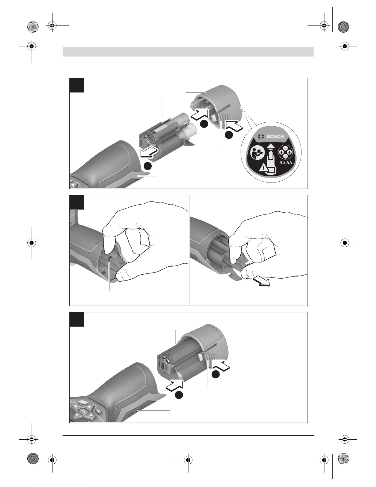
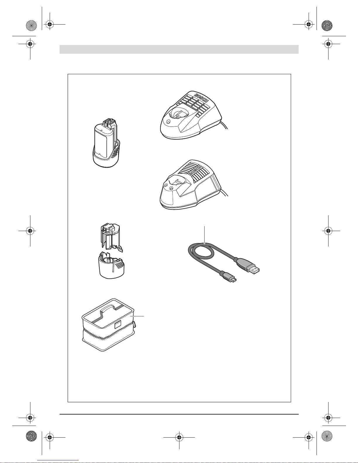
Operation with Battery Pack (see figure C)
Note: Use of battery packs not suitable for the measuring tool
can lead to malfunctions of or cause damage to the measuring
tool.
Note: The battery pack is supplied partially charged. To en-
sure full capacity of the battery pack, completely charge the
battery pack in the battery charger before using for the first
time.
Use only the chargers listed in the technical data. Only
these battery chargers are matched to the lithium-ion bat-
tery of your measuring tool.
The lithium-ion battery pack can be charged at any time with-
out reducing its service life. Interrupting the charging proce-
dure does not damage the battery pack.
Following the automatic shut off of the measuring tool,
do not continue to press the On/Off button. The battery
can be damaged.
To insert the charged battery pack 23, slide it into the battery
port 18 until you feel it engage and it is flush with the handle
of the measuring tool.
To remove the battery pack 23, press the unlocking buttons
19 and pull the battery pack out of the battery port 18. Do not
use force to do this.
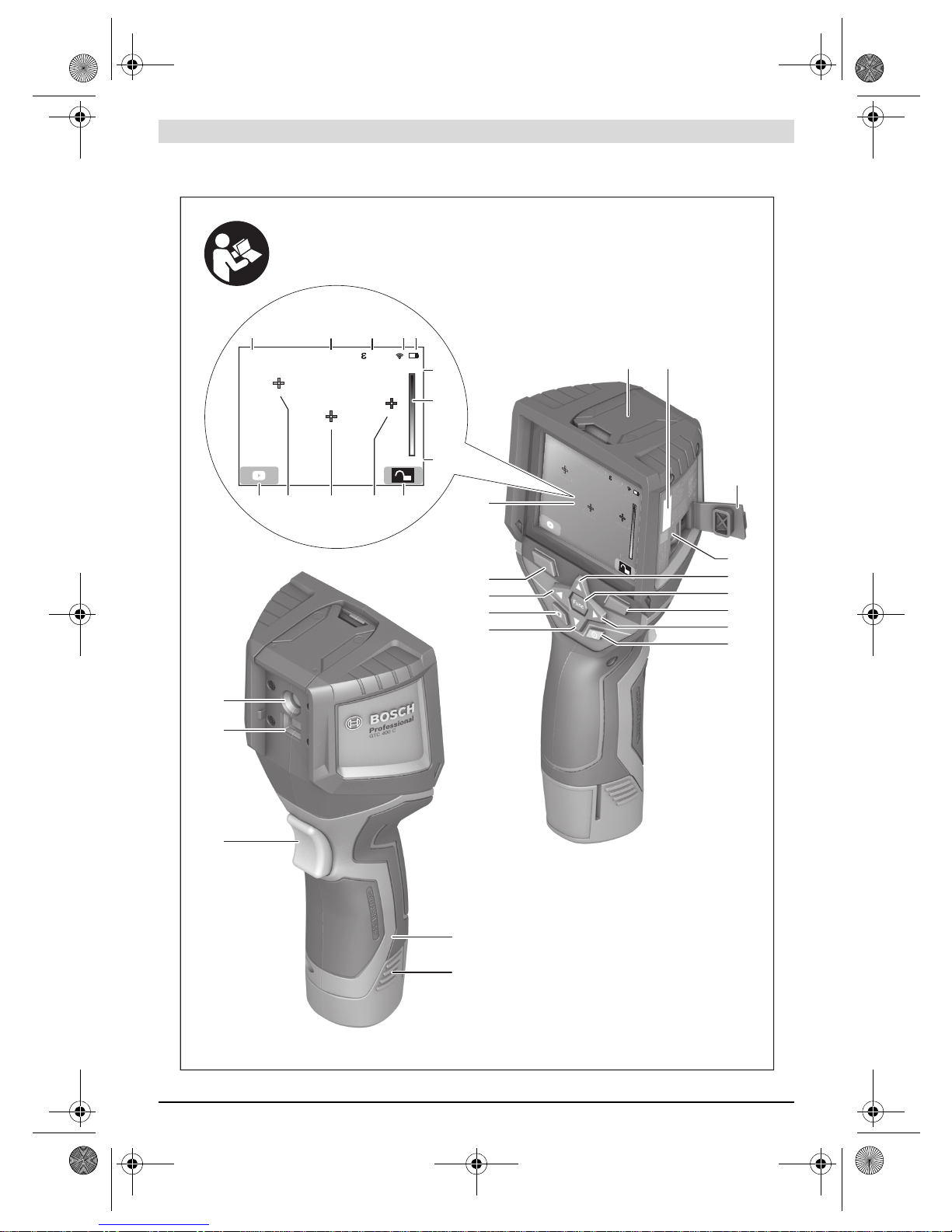
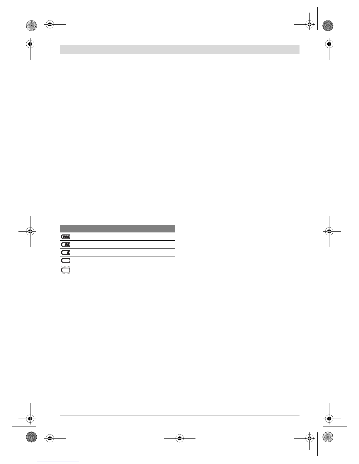
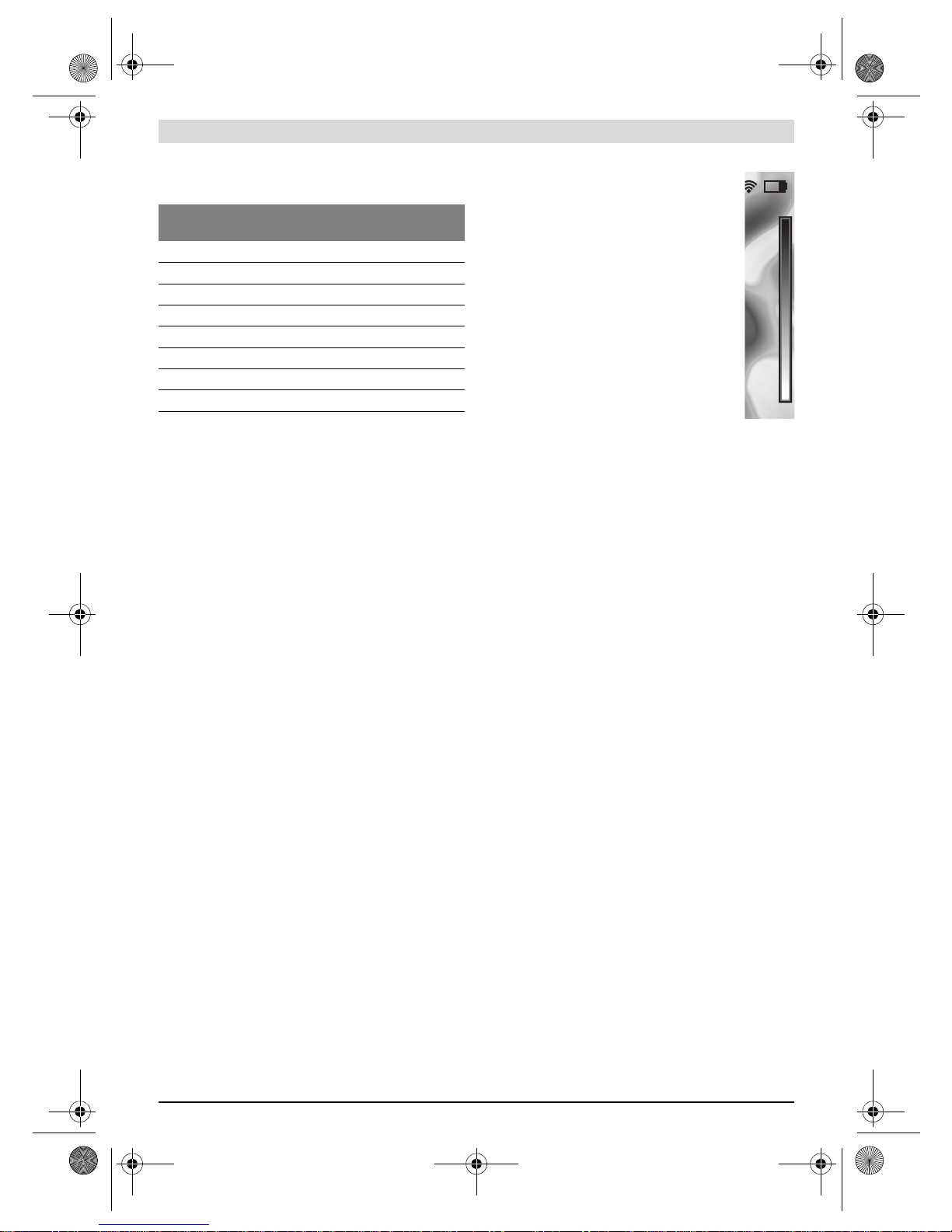
Battery Status Indicator
The battery status indicator eon the display shows the charg-
ing state of the batteries or battery pack 23.
Operation
Protect the measuring tool against moisture and direct
sun light.
Do not subject the measuring tool to extreme tempera-
tures or variations in temperature. As an example, do
not leave it in vehicles for a long time. In case of large vari-
ations in temperature, allow the measuring tool to adjust to
the ambient temperature before putting it into operation.
In case of extreme temperatures or variations in tempera-
ture, the accuracy of the measuring tool can be impaired.
Make sure that the measuring tool is correctly acclima-
tised. In the event of severe temperature fluctuations or
environmental conditions which vary to a large degree, the
measurement accuracy of the measuring tool may be im-
paired until it is fully acclimatised again.
Avoid hard knocks to the measuring tool or dropping it.
After severe external influences and in the event of abnor-
malities in the functionality, you should have the measur-
ing tool checked by an authorised Bosch after-sales ser-
vice agent.
Initial Operation
Switching On and Off
To take a measurement, fold the protective cap 1upwards.
Make sure that the infrared measuring area is not closed
off or covered while working.
To switch on the measuring tool, press the On/Off button 9.
A start sequence will appear in the display 14. After the start
sequence, the measuring tool will immediately begin to meas-
ure and will measure continuously until it is switched off.
Note: In the first few minutes, the measuring tool may self-
calibrate several times, as the sensor temperature and ambi-
ent temperature have not yet been brought into line. Perform-
ing calibration again enables precise measurement. The ther-
mal image freezes briefly during calibration.
To switch off the measuring tool, press the On/Off button
again. The measuring tool saves all settings and then switches
itself off. Close the protective cap 1to transport the measur-
ing tool safely.
In the “Settings” menu, you can choose whether and after how
much time the measuring tool automatically switches off (see
“Switch-off time”, page 12).
If the battery or the measuring tool is not within the operating
temperature range stated in the Technical Data, the measur-
ing tool will shut down automatically after a brief warning (see
“Troubleshooting – Causes and Corrective Measures”,
page 13). Allow the measuring tool to reach to the correct
temperature and then switch it back on.
Preparing for Measurement
Setting the Emissivity Degree for Surface-temperature
Measurements
The emissivity degree of an object depends on the material
and the structure of its surface. It indicates whether an object
(in comparison with other objects with the same tempera-
ture) emits much or little infrared heat radiation.
To determine the surface temperature, the tool performs a
contactless measurement of the natural infrared thermal radi-
ation emitted by the object at which the tool is aimed. To en-
sure correct measurement, the emissivity setting on the
measuring tool must be checked before every measure-
ment and adapted to the measuring object if necessary.
You can select one of the preset emissivity levels or enter an
exact numerical value. Adjust the required emissivity using
the “Measurement” >“Emissivity” menu (see page 11).
Temperature measurements will only be correct if the
emissivity setting and the emissivity of the object
match.
Differences in colour may be caused by different tempera-
tures and/or different emissivity levels. If the emissivity levels
are very different, the depicted temperature differences may
differ considerably from the actual temperature differences.
If there are multiple objects made of different materials or
that have different structures in the measurement range, the
displayed temperature values are only conclusive for the ob-
jects that match the emissivity setting. For all other objects
Indication Capacity
>2/3
≤2/3
≤1/3
≤10 %
Changing the Batteries or Battery Pack
gtc400c_BUCH-3220-004.book Seite 9 Mittwoch, 9. Mai 2018 9:19 09

10 | English
1 609 92A 4FJ | (9.5.18) Bosch Power Tools
(with different emissivity levels), the displayed colour differ-
ences can be used as an indication of temperature relation-
ships.
Notes on the Measuring Conditions
Highly reflective or shiny surfaces (e.g. shiny tiles or polished
metals) may distort or impair the results shown. If necessary,
mask the surface to be measured with a dark, matt adhesive
tape that conducts heat well. Allow the tape to acclimatise
briefly on the surface.
Make sure that a favourable measuring angle is used on reflec-
tive surfaces in order to ensure that the thermal radiation re-
flected by other objects does not distort the result. For exam-
ple, the reflection of your own body heat may interfere with
the measurement when measuring head-on from a perpendic-
ular position. On a level surface, the outline and temperature
of your body could therefore be displayed (reflected value),
and these values do not correspond to the actual temperature
of the measured surface (emitted value or real value of the
surface).
Measuring through transparent materials (e.g. glass or trans-
parent plastics) is fundamentally not possible.
The accuracy and reliability of the measuring results increase
with better and more stable measuring conditions.
Infrared temperature measurement is impaired by smoke,
vapour/high air humidity or dusty air.
Information for achieving improved measurement accuracy:
– Get as close as possible to the measuring object to mini-
mise interfering factors between you and the surface to be
measured.
– Ventilate indoor areas prior to measurement, especially
when the air is contaminated or extremely steamy.
After ventilating, allow the room to acclimatize for a while
until the usual temperature has been reached again.
Assigning temperatures on the basis of the scale
A scale is shown on the right-hand side of the dis-
play. The values at the top and bottom end are ori-
ented to the maximum and minimum temperature
recorded in the thermal image. Colours are as-
signed to temperature values with a uniform distri-
bution in the image (linearly).
Different shades can therefore be used to assign
temperatures within these two limit values. For ex-
ample, a temperature that is exactly between the
maximum and minimum value can be assigned to
the centre colour range of the scale.
To determine the temperature of a specific area,
move the measuring tool so that the crosshairs
with temperature display kare aimed at the re-
quired point or area.
In the automatic setting, the colour spectrum of
the scale is always distributed linearly (= uniformly) across
the entire measurement range between the maximum and
minimum temperatures.
The thermal imaging camera displays all measured tempera-
tures in the measurement range in relation to one another. If
heat is displayed as blue in the colour palette in an area, for
example in a colour representation, this means that the blue
areas are among the colder measured values in the current
measurement range. However, these areas may be in a tem-
perature range that could cause injuries in certain circum-
stances. You should therefore always note the temperatures
displayed on the scale or at the crosshairs themselves.
Functions
Adjusting the colour display
Depending on the measurement conditions, different colour
palettes can make it easier to analyse the thermal image and
show objects or circumstances more clearly in the display.
This does not affect the measured temperatures. Only the
way in which the temperature values are shown changes.
To change the colour palette, remain in measuring mode and
press the right-hand 8or left-hand 12 arrow button.
Superimposition of thermal image and real image
For improved orientation (= local assignment of the thermal
image displayed), with matched temperature ranges, a visual
real image can additionally be inserted.
Note: The superimposition of the real image and thermal im-
age is accurate at a distance of 0.55 m. If the tool is closer to
or further away from the object being measured, this may re-
sult in misalignment of the real image and thermal image.
The thermal imaging camera offers you the following options:
–Complete infrared image
Only the thermal image is displayed.
–Image in image
The thermal image displayed is cropped and the surround-
ing area is shown as a real image. This setting improves the
local assignment of the measurement range.
Material Emissivity
(reference value 0 °Cto100 °C)
Concrete 0.93
Plaster/mortar 0.93
Roofing tiles 0.93
Roofing felt 0.93
Radiator paint 0.93
Wood 0.91
Linoleum 0.88
Paper 0.89
21,8 °C
32,5 °C
gtc400c_BUCH-3220-004.book Seite 10 Mittwoch, 9. Mai 2018 9:19 09

English | 11
Bosch Power Tools 1 609 92A 4FJ | (9.5.18)
–Transparency
The thermal image displayed is placed on top of the real im-
age in such a way that it is slightly transparent. This ena-
bles improved detection of objects.
You can adjust the setting by pressing the up 5or down 10
arrow buttons.
Fixing the scale
The colour distribution in the thermal image is adjusted auto-
matically but can be fixed by pressing the right-hand function
button 7. This enables a comparison to be made between
thermal images taken under different temperature conditions
(e.g. when checking several rooms for thermal bridges).
To switch the scale back to automatic, press the right-hand func-
tion button 7again. The temperatures are now dynamic again
and adapt to the measured minimum and maximum values.
Measuring functions
To call up further functions which may be helpful for the dis-
play, press the “Func” button 6. Use the right-hand/left-hand
buttons to navigate through the displayed options to select a
function. Select a function and press the “Func” button 6
again.
The following measuring functions are available:
–“Automatic”
Colours are distributed automatically in the thermal image
–“Heat detector”
Only the warmer temperatures in the measurement range
are displayed as a thermal image in this measuring func-
tion. The area outside these warmer temperatures is dis-
played in greyscale as a real image so that coloured objects
are not wrongly associated with temperatures (e.g. red ca-
ble in the control cabinet when looking for overheated
components). Adjust the scale using the up 5and down 10
buttons. This expands or reduces the temperature range
shown.
The tool continues to measure minimum and maximum
temperatures and displays these at the ends of the scale.
You can, however, control which temperature range is
shown in colour as a thermal image.
–“Cold detector”
Only the colder temperatures in the measurement range
are displayed as a thermal image in this measuring func-
tion. The area outside these colder temperatures is dis-
played in greyscale as a real image so that coloured objects
are not wrongly associated with temperatures (e.g. blue
window frame when looking for faulty insulation). Adjust
the scale using the up 5and down 10 buttons. This ex-
pands or reduces the temperature range shown.
The tool continues to measure minimum and maximum
temperatures and displays these at the ends of the scale.
You can, however, control which temperature range is
shown in colour as a thermal image.
–“Manual”
If greatly deviating temperatures are measured in the ther-
mal image (e.g. radiator as a hot object when searching for
thermal bridges), the available colours are distributed
among a large number of temperature values in the range
between the maximum and the minimum temperature.
This can result in a situation where subtle temperature dif-
ferences can no longer be shown in detail. To obtain a
detailed depiction of the focus temperature, switch to
“Manual” mode and set the maximum and the minimum
temperature. Doing this enables you to set the tempera-
ture range that is relevant to you and in which you would
like to detect subtle differences. The Reset setting auto-
matically readjusts the scale to the measured values in the
infrared sensor’s field of view.
Main Menu
To access the main menu, press the “Func” button 6to call up
the measuring functions. Now press the right-hand function
button 7.
–“Measurement”
–“Display”
–“WiFi”: “ON/OFF”
(see “Data Transmission”, page 12)
–“Tool”
–“Emissivity” c:
A selection of saved emissivity levels is available for
some of the most common materials. Select the appro-
priate material in the “Material” menu item. The corre-
sponding emissivity is displayed in the line below.
If you know the exact emissivity of the object to be meas-
ured, you can also set it as a numerical value in the
“Emissivity” menu item.
–“Reflected temperature”:
Setting this parameter improves the accuracy of meas-
uring results, especially with low-emissivity (= high-re-
flection) materials. The reflected temperature normally
corresponds to the ambient temperature.
If there are objects with greatly deviating temperatures
close to highly reflective objects which could affect the
measurement, this value should be adjusted.
–“Hotspot” j: “ON/OFF”
In this function, the hottest point (= measuring pixel) in
the measurement range is automatically highlighted by
red crosshairs in the thermal image. This can help you to
detect a critical point, e.g. to locate a loose terminal in
the control cabinet.
–“Cold spot” l: “ON/OFF”
The coldest point (= measuring pixel) in the measure-
ment range is automatically highlighted by blue cross-
hairs in the thermal image. This can help you to detect a
critical point, e.g. to locate a leak in insulation.
–“Crosshairs” k: “ON/OFF”
The crosshairs are displayed in the centre of the thermal
image and show you the measured temperature value at
this point.
–“Scale” g: “ON/OFF”
–“Language”
Under this menu item, you can change the language for
all displays.
gtc400c_BUCH-3220-004.book Seite 11 Mittwoch, 9. Mai 2018 9:19 09

12 | English
1 609 92A 4FJ | (9.5.18) Bosch Power Tools
You can also press button 17 to exit any menu and return to
the standard display screen.
Documenting measurements
Saving measurements
The measuring tool begins to take measurements as soon as it
is switched on and does so continuously until it is switched off.
To save an image, point the camera at the desired measuring
object and press the “Save” button 11. The image is saved in
the camera’s internal memory. Alternatively, press the
“Freeze measurement” button 17. The measurement is fro-
zen and shown in the display. This enables you to take as
much time as you need to look at the image. If you do not wish
to save the frozen image, press button 17 to return to meas-
uring mode. If you wish to save the image in the camera’s in-
ternal memory, press the “Save” button 11.
Calling up saved images
Proceed as follows to call up saved thermal images:
– Press the left-hand function button 13. The most recently
saved photo now appears in the display.
– Press the right-hand 8or left-hand 12 arrow button to
switch between the saved thermal images.
Deleting saved images
Go to the gallery view to delete individual thermal images:
– Press the right-hand function button 7under the waste pa-
per basket symbol.
– Confirm the operation by pressing the left-hand function
button 13 or terminate the deletion process by pressing
the right-hand function button 7under the cancel symbol.
Delete all images
In the “Delete all images” menu, you can delete all the files in
the internal memory at once.
Press the “Func” 6button to call up the measuring functions.
Now press the right-hand function button 7and select
“Tool” > “Delete all images”. Press the right-hand arrow
button 8to enter the submenu. Then press either the left-
hand function button 13 under the tick symbol to delete all
files, or the right-hand function button 7under the cross sym-
bol to cancel the operation.
Data Transmission
Data Transmission via USB Interface
Open the cover on the micro USB port 3. Connect the micro
USB port on the measuring tool to your PC or laptop using the
micro USB cable provided.
Now press button 9to switch on the thermal imaging camera.
Open the file browser and select the “BOSCH GTC 400 C”
drive. The saved JPG files can be copied, moved to your com-
puter or deleted from the internal memory of the measuring
tool.
As soon as you have ended the required operation, discon-
nect the drive following the standard procedure and then use
button 9to switch the thermal imaging camera off again.
Remove the micro USB cable during the measurement opera-
tion and close the cover 3.
Attention: Always disconnect the drive from your operating
system first (eject drive), as failure to do so may damage the
thermal imaging camera’s internal memory.
Always keep the cover of the USB interface closed so that
dust and splashes cannot enter the housing.
Note: Only connect the measuring tool to a PC or notebook.
The tool could be damaged if you connect it to a different de-
vice.
Note: The micro USB interface can only be used for data
transmission – it is not suitable for charging batteries.
Post-editing the thermal images
You can post-edit the saved thermal images on your computer
if it uses a Windows operating system. To do so, download the
GTC Transfer software from the product page for the thermal
imaging camera at
www.bosch-professional.com/gtc.
Data transmission via WiFi
The measuring tool is equipped with a WiFi module which en-
ables the saved images to be wirelessly transmitted from your
thermal imaging camera to a mobile device.
The “Measuring Master” application (app) is required as the
software interface for this. You can download this from the
store for your end device type:
–“Time & Date” a
To change the date and time in the display, open the
“Time & Date” submenu. In this submenu you can also
change the date and time format.
To exit the “Time & Date” submenu, press either the
left-hand function button 13 under the tick symbol to
save the settings or the right-hand function button 7un-
der the cross symbol to discard the changes.
–“Audio signals”: “ON/OFF”
Under this menu item, you can switch the audio signals
on or off.
–“Switch-off time”
Under this menu item, you can select the time interval
after which the measuring tool will automatically switch
off if no buttons are pressed. You can also deactivate the
automatic switch-off by selecting the “Never” setting.
–“Delete all images”
Under this menu item, you can delete all the files in the
internal memory at once. Press the right-hand arrow
button 8for “more ...” to enter the submenu. Then
press either the left-hand function button 13 under the
tick symbol to delete all files, or the right-hand function
button 7under the cross symbol to cancel the operation.
–“Tool information”
Under this menu item, you can access information about
the measuring tool. There you can find the serial number
of the measuring tool and the installed software version.
gtc400c_BUCH-3220-004.book Seite 12 Mittwoch, 9. Mai 2018 9:19 09

English | 13
Bosch Power Tools 1 609 92A 4FJ | (9.5.18)
In addition to wirelessly transmitting your images, the
“Measuring Master” application makes it possible for you to
use an extended range of functions and facilitates post-edit-
ing and forwarding of measured data (for example via e-mail).
Information about system requirements for a WiFi connection
can be found on the Bosch website at
“www.bosch-professional.com/gtc”.
To activate or deactivate the WiFi connection on the measur-
ing tool, call up the main menu, use the buttons to select
“WiFi” and activate or deactivate it. dwill appear on the dis-
play. Ensure that the WiFi interface is activated on your mo-
bile device.
The connection between the mobile device and the measur-
ing tool can be established after the Bosch application has
been started (if WiFi modules are activated). To do this, fol-
low the instructions in the “Measuring Master” applica-
tion.
Troubleshooting – Causes and Corrective Measures
In the event of a fault, the tool will restart and can then continue to be used. If the fault persists, the following overview may
help you.
Definitions
Infrared heat radiation
Infrared heat radiation is electromagnetic radiation emitted
by every body. The amount of radiation depends on the tem-
perature and the emissivity degree of the body.
Emissivity Degree
The emissivity degree of an object depends on the material
and the structure of its surface. It states how much infrared
heat radiation the object emits compared to an ideal heat
emitter (black body, emissivity degree = 1).
Thermal Bridge
A thermal bridge is an object that undesirably transmits heat
outwardsorinwards, thereforedifferingsignificantly fromthe
temperature of the rest of a wall or from the desired tempera-
ture of a wall.
As the surface temperature at thermal bridges is lower than in
the rest of the room, the risk of mould increases significantly
at these locations.
Reflected temperature/reflectivity of an object
The reflected temperature is the thermal radiation that is not
emitted by the object itself. Depending on the structure and
material, background radiation is reflected in the object to be
measured, therefore distorting the actual temperature result.
Error Cause Corrective Measure
Measuring tool cannot be switched on. Battery pack or batteries
empty
Charge the battery pack or change the batteries.
Battery too warm or too cold Allow the battery to reach the correct temperature or
change it.
Measuring tool too warm or
too cold
Allow the measuring tool to reach the correct temper-
ature.
Image memory defective Format the internal memory by deleting all images
(see “Delete all images”, page 12). If the problem
persists, send the measuring tool to an authorised
Bosch after-sales service agent.
Image memory full If required, transfer the images to another storage
medium (e.g. computer or notebook). Then delete
the images in the internal memory.
Measuring tool is defective. Send the measuring tool to an authorised Bosch
after-sales service agent.
Measuring tool cannot be connected
to a computer.
Measuring tool not recog-
nised by computer.
Check whether the driver on your computer is up to
date. It may be necessary to have a newer operating
system version on your computer.
Micro USB connection or
micro USB cable defective
Check whether the measuring tool can be connected
to a different computer. If not, send the measuring
tool to an authorised Bosch after-sales service agent.
gtc400c_BUCH-3220-004.book Seite 13 Mittwoch, 9. Mai 2018 9:19 09

14 | English
1 609 92A 4FJ | (9.5.18) Bosch Power Tools
Distance from the object
The distance between the object being measured and the
measuring tool influences the captured area size per pixel.
You can capture increasingly large objects as the distance
from the object becomes greater.
Maintenance and Service
Maintenance and Cleaning
Store and transport the measuring tool only in a suitable con-
tainer such as the original packaging or the protective pouch
(accessory). Do not affix any stickers near to the infrared sen-
sor on the measuring tool.
Keep the measuring tool clean at all times.
When cleaning, fluids should not penetrate into the measur-
ing tool.
Do not attempt to remove dirt from the sensor, camera or re-
ception lens using pointed objects, and do not wipe over the
camera and reception lens (risk of scratching).
If you would like your measuring tool to be recalibrated,
please contact a Bosch service centre (for addresses, see
section “After-sales Service and Application Service”).
If the event of a repair, send in the measuring tool in the origi-
nal packaging or in the protective pouch (accessory).
The integrated button cell may only be removed for disposal
by qualified personnel. Opening the housing shell can destroy
the measuring tool. Unscrew the screws on the housing and
remove the housing shell in order to remove the button cell.
After-sales Service and Application Service
Our after-sales service responds to your questions concern-
ing maintenance and repair of your product as well as spare
parts. Exploded views and information on spare parts can al-
so be found under:
www.bosch-pt.com
Bosch’s application service team will gladly answer questions
concerning our products and their accessories.
In all correspondence and spare parts orders, please always
include the 10-digit article number given on the nameplate of
the product.
Cambodia
Robert Bosch (Cambodia) Co., Ltd
Unit 8BC, GT Tower, 08th Floor, Street 169,
Czechoslovakia Blvd, Sangkat Veal Vong
Khan 7 Makara, Phnom Penh
VAT TIN: 100 169 511
Tel.: +855 23 900 685
Tel.: +855 23 900 660
www.bosch.com.kh
People’s Republic of China
China Mainland
Bosch Power Tools (China) Co., Ltd.
567, Bin Kang Road
Bin Jiang District 310052
Hangzhou, P.R.China
Tel.: 4008268484
Fax: (0571) 87774502
E-Mail: [email protected]
www.bosch-pt.com.cn
HK and Macau Special Administrative Regions
Robert Bosch Co. Ltd.
21st Floor, 625 King’s Road
North Point, Hong Kong
Customer Service Hotline: +852 2101 0235
Fax: +852 2590 9762
E-Mail: [email protected]
www.bosch-pt.com.hk
India
Bosch Service Center
69, Habibullah Road, (Next to PSBB School), T. Nagar
Chennai–600077
Phone: (044) 64561816
Bosch Service Center Rishyamook
85A, Panchkuin Road
New Delhi–110001
Phone: (011) 43166190
Bosch Service Center
79, Crystal Bldg., Dr. Annie Besant Road, Worli
Mumbai–400018
Phone: (022) 39569936 / (022 )39569959 /
(022) 39569967 / (022) 24952071
Indonesia
PT Robert Bosch
Palma Tower 10th Floor
Jalan RA Kartini II-S Kaveling 6
Pondok Pinang, Kebayoran Lama
Jakarta Selatan 12310
Tel.: (21) 3005-5800
www.bosch-pt.co.id
Malaysia
Robert Bosch Sdn. Bhd.(220975-V) PT/SMY
No. 8A, Jalan 13/6
46200 Petaling Jaya
Selangor
Tel.: (03) 79663194
Toll-Free: 1800 880188
Fax: (03) 79583838
E-Mail: [email protected]
www.bosch-pt.com.my
Pakistan
Robert Bosch Middle East FZE – Pakistan Liaison Office
2nd Floor Plaza # 10, CCA Block, DHA Phase 5
Lahore, 54810
Phone: +92(303)4444311
Email: [email protected]
Distance (m) Size of infrared
pixels (mm)
Infrared range
width x height (m)
0.5 3 ~0.5 x 0.4
16 ~1 x 0.75
212 2.05 x 1.5
530 5.1 x 3.8
gtc400c_BUCH-3220-004.book Seite 14 Mittwoch, 9. Mai 2018 9:19 09

English | 15
Bosch Power Tools 1 609 92A 4FJ | (9.5.18)
Philippines
Robert Bosch, Inc.
28th Floor Fort Legend Towers,
3rd Avenue corner 31st Street,
Fort Bonifacio, Global City,
1634 Taguig City
Tel.: (632) 8703871
Fax: (632) 8703870
www.bosch-pt.com.ph
Singapore
Powerwell Service Centre Ptd Ltd
Bosch Authorised Service Centre (Power Tools)
4012 Ang Mo Kio Ave 10, #01-02 TECHplace
Singapore 569628
Tel.: 6452 1770
Fax: 6452 1760
E-Mail: [email protected]
www.powerwellsc.com
www.bosch-pt.com.sg
Thailand
Robert Bosch Ltd.
Liberty Square Building
No. 287, 11 Floor
Silom Road, Bangrak
Bangkok 10500
Tel.: 02 6393111
Fax: 02 2384783
Robert Bosch Ltd., P. O. Box 2054
Bangkok 10501
www.bosch.co.th
Bosch Service – Training Centre
La Salle Tower Ground Floor Unit No.2
10/11 La Salle Moo 16
Srinakharin Road
Bangkaew, Bang Plee
Samutprakarn 10540
Tel.: 02 7587555
Fax: 02 7587525
Vietnam
Branch of Bosch Vietnam Co., Ltd in HCMC
Floor 10, 194 Golden Building
473 Dien Bien Phu Street
Ward 25, Binh Thanh District, Ho Chi Minh City
Tel.: (08) 6258 3690
Fax: (08) 6258 3692
Hotline: (08) 6250 8555
www.bosch-pt.com.vn
Armenia, Azerbaijan, Georgia, Kyrgyzstan, Mongolia,
Tajikistan, Turkmenistan, Uzbekistan
TOO “Robert Bosch” Power Tools, After Sales Service
Rayimbek Ave., 169/1
050050, Almaty, Kazakhstan
Official Website: www.bosch.com, www.bosch-pt.com
Bahrain
Hatem Al Juffali Technical Equipment Establishment.
Kingdom of Bahrain, Setra Highway, Al Aker Area
Phone: +966126971777-311
Fax: +97317704257
Email: [email protected]
Egypt
Unimar
20 Markaz kadmat
El tagmoa EL Aoul – New Cairo
Phone:+20222476091-95
Phone:+20222478072-73
Fax: +20 2224 78075
Email: [email protected]
Iran
Robert Bosch Iran
3rd Floor, No 3, Maadiran Building
Aftab St., Khodami St., Vanak Sq.
Tehran 1994834571
Phone: +9821- 86092057
Iraq
Sahba Technology Group
Al Muthana airport road
Baghdad
Phone: +9647901906953
Phone Dubai: +97143973851
Email: [email protected]
Jordan
Roots Arabia – Jordan
Nasser Bin Jameel street, Building 37 Al Rabiah
11194 Amman
Phone: +962 6 5545778
Email: [email protected]
Kuwait
Al Qurain Automotive Trading Company
Shuwaikh Industrial Area, Block 1, Plot 16, Street 3rd
P.O. Box 164 – Safat 13002
Phone: 24810844
Fax: 24810879
E-mail: [email protected]
Lebanon
Tehini Hana & Co. S.A.R.L.
P.O. Box 90-449
Jdeideh
Dora-Beirut
Phone: +9611255211
Email: [email protected]
Libya
El Naser for Workshop Tools
Swanee Road, Alfalah Area
Tripoli
Phone: +218 21 4811184
gtc400c_BUCH-3220-004.book Seite 15 Mittwoch, 9. Mai 2018 9:19 09

16 | English
1 609 92A 4FJ | (9.5.18) Bosch Power Tools
Oman
Malatan Trading & Contracting LLC
P.O. Box 131
Ruwi, 112 Sultanate of Oman
Phone: +968 99886794
Email: [email protected]
Qatar
International Construction Solutions W L L
P. O. Box 51, Doha
Phone: +974 40065458
Fax: +974 4453 8585
Email: [email protected]
Saudi Arabia
Juffali Technical Equipment Co. (JTECO)
Kilo 14, Madinah Road, Al Bawadi District
Jeddah 21431
Phone: +966 2 6672222 Ext. 1528
Fax: +966 2 6676308
Email: [email protected]
Syria
Dallal Establishment for Power Tools
P.O. Box 1030
Aleppo
Phone: +963212116083
Email: [email protected]
United Arab Emirates
Central Motors & Equipment LLC, P.O. Box 1984
Al-Wahda Street – Old Sana Building
Sharjah
Phone: +971 6 593 2777
Fax: +971 6 533 2269
Email: [email protected]
Yemen
Abualrejal Trading Corporation
Sana’a Zubiery St. Front to new Parliament Building
Phone: +967-1-202010
Fax: +967-1-279029
Email: [email protected]
Ethiopia
Forever plc
Kebele 2,754, BP 4806,
Addis Ababa
Phone: +251 111 560 600
Email: [email protected]
Ghana
C.WOERMANN LTD.
Nsawam Road/Avenor Junction, P.O. Box 1779
Accra
Phone: +233 302 225 141
Kenya
Robert Bosch East Africa Ltd
Mpaka Road P.O. Box 856
00606 Nairobi
Nigeria
Robert Bosch Nigeria Ltd.
52–54 Isaac John Street P.O. Box
GRA Ikeja – Lagos
Republic of South Africa
Customer service
Hotline: (011) 6519600
Gauteng – BSC Service Centre
35 Roper Street, New Centre
Johannesburg
Tel.: (011) 4939375
Fax: (011) 4930126
E-Mail: [email protected]
KZN – BSC Service Centre
Unit E, Almar Centre
143 Crompton Street
Pinetown
Tel.: (031) 7012120
Fax: (031) 7012446
E-Mail: [email protected]
Western Cape – BSC Service Centre
Democracy Way, Prosperity Park
Milnerton
Tel.: (021) 5512577
Fax: (021) 5513223
E-Mail: [email protected]
Bosch Headquarters
Midrand, Gauteng
Tel.: (011) 6519600
Fax: (011) 6519880
E-Mail: [email protected]
Tanzania
Diesel & Autoelectric Service Ltd.
117 Nyerere Rd., P.O. Box 70839
Vingunguti 12109, Dar Es Salaam
Phone: +255 222 861 793/794
Australia, New Zealand and Pacific Islands
Robert Bosch Australia Pty. Ltd.
Power Tools
Locked Bag 66
Clayton South VIC 3169
Customer Contact Center
Inside Australia:
Phone: (01300) 307044
Fax: (01300) 307045
Inside New Zealand:
Phone: (0800) 543353
Fax: (0800) 428570
Outside AU and NZ:
Phone: +61 3 95415555
www.bosch-pt.com.au
www.bosch-pt.co.nz
Supplier code ERAC000385
gtc400c_BUCH-3220-004.book Seite 16 Mittwoch, 9. Mai 2018 9:19 09

中文 | 17
Bosch Power Tools 1 609 92A 4FJ | (9.5.18)
Transport
The usable lithium-ion battery packs are subject to the Dan-
gerous Goods Legislation requirements. The user can trans-
port the battery packs by road without further requirements.
When being transported by third parties (e.g. via air transport
or forwarding agency), special requirements on packaging
and labelling must be observed. For preparation of the item
being shipped, consulting an expert for hazardous material is
required.
Dispatch battery packs only when the housing is undamaged.
Tape or mask off open contacts and pack up the battery pack in
such a manner that it cannot move around in the packaging.
Please also observe possibly more detailed national regulations.
Disposal
Measuring tools, battery packs/batteries, accesso-
ries and packaging should be sorted for environmen-
tal-friendly recycling.
Do not dispose of measuring tools and batteries/re-
chargeable batteries into household waste!
Battery packs/batteries:
Li-ion:
Please observe the instructions in section “Transport”,
page 17.
Subject to change without notice.
中文
安全规章
必须阅读并注意所有说明。 如果不按照
给出的说明使用测量仪,可能会影响集
成在测量仪中的保护功能。请妥善保存
这些说明。
本仪器只能交给合格的专业人员修理,而且只能使
用原厂的备件。 如此才能够确保仪器的安全性能。
不要在易爆环境,如有易燃液体、气体或粉尘的环
境下操作测量仪器。 测量仪器内可能产生火花并点
燃粉尘和气体。
在测量仪上进行任何工作 (例如安装、维护等)以
及搬运、保存测量仪之前,都必须从设备中取出电
池或蓄电池。
不可以打开蓄电池。 有短路的危险。
蓄电池必须远离高温,蓄电池也要避开持续
的日照、火焰、水和湿气。 有爆炸的危险。
不使用的蓄电池要远离回纹针、硬币、钥匙、钉
子、螺丝或其他可能桥接触点的小金属物体。 蓄电
池的触点如果产生短路,可能着火或造成火灾。
如果滥用蓄电池,可能从蓄电池中渗出液体。避免
接触此液体。如果不小心碰触了要用水冲刷。万一
该液体进入眼中必须尽快就医。 从蓄电池渗出的液
体可能刺激皮肤或灼伤皮肤。
损坏的和被滥用的蓄电池会冒出蒸气,因此要确保
工作场所空气流通。身体如果出现任何不适得尽快
就医。 此蒸气可能刺激呼吸道。
只能使用制造厂商推荐的充电器为蓄电池充电。
使用针对特定蓄电池的充电器替其他的蓄电池充
电,可能会酿成火灾。
本蓄电池只能安装在博世的测量仪器上使用。 只有
这样才能够保护蓄电池,避免发生危险的过载情
形。
钉子、螺丝刀等尖锐物品或外力作用可能会损坏电
池。 有可能出现内部短路并导致电池燃烧、冒烟、
爆炸或过热。
电池适配器仅用于特定的博世测量仪,不允许配合
电动工具使用。
不使用测量仪时,必须从仪器中取出电池。 长期搁
置之后,电池会腐蚀或自行放电。
请保护好测量仪,尤其是摄像头和红外镜头部位,
避免受到雨雪影响。 接收镜头可能会蒙上雾气,使
测量结果失真。错误的设备设置及其它环境影响因
素可能会导致测量错误。显示的物体温度可能会较
热或较冷,因而当触摸物体时可能会发生危险。
热成像中较高的温度差可能会导致即使温度较高也
显示出与低温相关的颜色。 触摸这类表面可能会导
致烫伤!
只有当设置的辐射率和物体辐射率一致时,才能正
确测量温度。 显示的物体温度和 / 或颜色可能会
较热或较冷,因而当触摸物体时可能会发生危险。
本测量仪装备了一个无线接口。必须注意本地运行
限制,例如在飞机上或医院里。
产品和功率描述
按照规定使用机器
本热成像摄像头用于以非接触方式测量表面温度。
显示的热成像显示了红外镜头探测区域的温度分布,
因而能够用不同颜色区别显示温度偏差。
这样一来,在正确的使用条件下,本设备能无接触地
分析表面和物体的温差或温度异常,使零部件和 / 或
薄弱位置变得可见,例如:
–隔热和保温层 (例如找出热桥)
–地板和墙壁中的主动导热管或热水管 (例如地暖)
gtc400c_BUCH-3220-004.book Seite 17 Mittwoch, 9. Mai 2018 9:19 09

18 | 中文
1 609 92A 4FJ | (9.5.18) Bosch Power Tools
–过热的电气部件,例如保险丝或端子
–机械零件 (例如因球轴承损坏引起的过热)
不允许使用本测量仪测量人体和动物的温度或用于其
他医疗目的。
本测量仪不适用于测量气体或液体的表面温度。
插图上的机件
机件的编号和仪器详解图上的编号一致。
1可视摄像头和红外传感器保护盖
2序列号码
3Micro USB 插口盖板
4Micro USB 插口
5向上箭头键
6测量功能键 "Func"
7切换温度刻度自动固定 / 右侧功能键
8右向箭头键
9起停开关
10 向下箭头键
11 保存键
12 左向箭头键
13 图库键 / 左侧功能键
14 显示屏
15 可视摄像头
16 红外传感器范围
17 冻结测量 / 继续测量键
18 蓄电池室
19 充电电池 / 电池适配器解锁按键
20 电池适配器密封帽*
21 电池适配器外壳*
22 外壳凹口
23 蓄电池*
24 Micro USB 电缆
25 保护套*
*图表或说明上提到的附件,并非包含在供货范围中。
显示图
a日期 / 时间
b测量功能
c辐射率显示
dWiFi 接通 / 关闭显示
e电容量的显示灯号
f测量范围内表面最高温度显示
g刻度
h测量范围内表面最低温度显示
i刻度锁定图标
j热点显示 (举例)
k带温度显示的十字线
l冷点显示 (举例)
m图片集图标
技术数据
热成像摄像头 GTC 400 C
物品代码 3 601 K83 1..
红外线传感器分辨率 160 x 120
温度灵敏性 <50mK
自由光谱区 8–14 μm
视野 (FOV)53 x 43°
焦距 ≥0.3 米
焦点 固定
表面温度测量范围 –10...+400°C
仪器铭牌上的序列号码 ( 仪器详解上标示着 2 的位置 ) 便是仪器的识别码。
1) 当环境温度为 20–23 °C 且辐射率 > 0.999 时,测量距离为:0.3 m,工作时间:>5 min
2) 温度 <0 °C 时功率受限
使用附带的蓄电池所测得的技术数据。
gtc400c_BUCH-3220-004.book Seite 18 Mittwoch, 9. Mai 2018 9:19 09

中文 | 19
Bosch Power Tools 1 609 92A 4FJ | (9.5.18)
测量精度 (一般)
表面温度1)
–10...+10°C
10...100 °C
>+100 °C
±3 °C
±3 °C
±3 %
显示屏类型 TFT
显示屏尺寸 3.5"
显示屏解析度 320 x 240
图片格式 .jpg
每次存储过程的存储图片数量 1张热成像 (截屏)
1张虚拟实像,包括温度值 (元数据)
内部图像存储器 (常规)中的图像数目 500
内置虚拟摄像头
电池(碱-锰)
蓄电池 (锂离子)
4x1.5 伏特 LR6 (AA) ( 带电池适配器 )
10.8 伏特 /12 伏特
USB 接头 1.1
实时时钟电源
–纽扣电池
–电池使用寿命约为
CR2450 (3V 锂电池 )
60 月
无线连接 WiFi
WiFi 最大发射功率 30 毫瓦
WiFi 工作频率范围 2.400–2.483 GHz
重量符合 EPTA-Procedure 01:2014 0.54 公斤
尺寸 (长 x 宽 x 高) 233 x 95 x 63 毫米
保护等级 (不包含电池盒) IP 53
允许的环境条件
–充电温度
–工作温度2)
–储藏温度范围
–相对湿度 (无冷凝)
0...+45 °C
–10...+45°C
–20...+70°C
20... 80 %
建议使用的充电电池 GBA 10,8 V
GBA 12 V
推荐的充电器 AL 11.. CV
GAL 12.. CV
热成像摄像头 GTC 400 C
仪器铭牌上的序列号码 ( 仪器详解上标示着 2 的位置 ) 便是仪器的识别码。
1) 当环境温度为 20–23 °C 且辐射率 > 0.999 时,测量距离为:0.3 m,工作时间:>5 min
2) 温度 <0 °C 时功率受限
使用附带的蓄电池所测得的技术数据。
gtc400c_BUCH-3220-004.book Seite 19 Mittwoch, 9. Mai 2018 9:19 09

20 | 中文
1 609 92A 4FJ | (9.5.18) Bosch Power Tools
安装
供电
本测量仪可以使用市售电池 (AA 电池,型号 LR6 或
类似)或博世锂离子充电电池运行。
含电池适配器的运行 (可拔出)(参考插图 A)
电池应装在电池适配器中。
电池适配器仅用于特定的博世测量仪,不允许配合
电动工具使用。
要装入电池,请将电池适配器 21 的外壳推入电池仓
18 中。根据密封帽 20 上的图示将电池放入外壳中。
将密封帽推到外壳上方,直至能感觉到它卡入且与测
量仪手柄平齐。
要取出电池,则按压密封帽 20 的解锁按键
19,然后拔下密封帽。注意电池不要掉出。
支撑住测量仪,向上对准电池仓 18。取出
电池。要从蓄电池仓 18 中取出位于内部的
外壳 21,请将手深入外壳的凹口 22 中,然
后轻轻按压侧壁将其从测量仪中取出 (参考
插图 B)。
指示: 取出充电电池请勿使用工具 (例如螺丝起子
机),否则可能会折断外壳。
务必同时更换所有的电池。请使用同一制造厂商,相
同容量的电池。
不使用测量仪时,必须从仪器中取出电池。 长期搁
置之后,电池会腐蚀或自行放电。
以蓄电池驱动 (参考插图 C)
指示: 使用了不适合测量仪器的蓄电池可能造成测量
仪器故障或损坏测量仪器。
指示: 蓄电池在供货时只完成了部分充电。为了确保
它能够发挥最大的功效,首度使用前得先以充电器替
蓄电池充足电。
请只使用在技术参数中列出的充电器。 只有这些充
电器才与可用在本测量仪上的锂离子蓄电池相匹
配。
您可以随时替锂离子蓄电池充电,不必担心会缩短它
的使用寿命。中断充电过程也不会损坏蓄电池。
探测仪自动关闭后请勿继续按压开关按键。 否则可
能会损坏电池。
要装入已充电的蓄电池 23,请将该蓄电池推入蓄电池
仓18 中,直至能感觉到它卡入且与测量仪手柄平齐。
为拆卸充电电池 23,请按压解锁按钮 19,将充电电
池从电池仓 18 中抽出。在此过程中请勿过度用力。
蓄电池充电电量指示灯
显示屏中的充电电量指示灯 e显示电池或蓄电池 23
的充电电量。
正式操作
不可以让湿气渗入仪器中,也不可以让阳光直接照
射在仪器上。
仪器不可以曝露在极端的气候下,也不可以把仪器
放在温差相当大的环境中。 仪器不可以长期放置在
汽车中。如果仪器先后曝露在温差相当大的环境
中, 必须先等待仪器温度恢复正常后再使用仪器。
如果仪器曝露在极端的气候下或温差相当大的环境
中,会影响仪器的测量准确度。
注意测量仪正确的环境适应性。 当出现温度剧烈波
动或环境条件剧烈变化时,测量仪的测量精度会持
续受到影响,直到它重新完全适应。
避免测量仪剧烈碰撞或掉落。 在发生强烈的外界作
用后以及功能异常时,应将测量仪交由授权的博世
售后服务点进行检查
正式操作仪器
开动 / 关闭
测量时打开保护盖 1。在工作中请注意不要封闭或遮
挡红外测量范围。
要接通测量仪,请按压起停开关 9。在显示屏 14 中显
示启动顺序。启动顺序结束后,测量仪立刻开始测量
并自动连续运行直至关闭。
指示: 在最初几分钟内,测量仪可能会自动频繁调
校,因为此时传感器温度和环境温度尚未完成匹配。
重新校准后可以精确测量。热成像在校准期间会短时
冻结。
如需关闭测量仪,请再次按压起停开关。测量仪保存
所有设置,然后自动关闭。请合上保护盖 1,以确保
安全运输测量仪。
您可以在设置菜单中选择是否以及多久之后自动关闭
测量仪 (参见 " 关闭时间 ",第 22 页)。
如果蓄电池或测量仪超出技术参数中给出的工作温
度,则测量仪在发出一个短促的警告 (参见 " 故障 -
原因和处理措施 ",第 24 页)后自动关闭。使测量
仪调温,然后将其重新接通。
显示图 容量
>2/3
≤2/3
≤1/3
≤10 %
更换电池或蓄电池
gtc400c_BUCH-3220-004.book Seite 20 Mittwoch, 9. Mai 2018 9:19 09
Other manuals for GTC 400 C Professional
2
Table of contents
Languages:
Other Bosch Thermal Camera manuals

Bosch
Bosch Professional GIS 500 User manual

Bosch
Bosch GTC 400 C Professional User manual

Bosch
Bosch MIC412TIBUP13636N User manual

Bosch
Bosch GTC 400 C Professional User manual

Bosch
Bosch MIC Series 412TF User manual

Bosch
Bosch MIC 612 Series User manual

Bosch
Bosch MIC 612 Series User manual

Bosch
Bosch MIC 612 Series User manual

Bosch
Bosch MIC 612 Series User manual

Bosch
Bosch MIC 612 Series User manual