Page
8 Standards............................................................................................ 10
8.1 Standards used.................................................................................... 10
8.2 FCC...................................................................................................... 11
8.3 CE marking........................................................................................... 11
8.3.1 Declaration of conformity.................................................................... 11
8.4 UL/CSA certified.................................................................................. 11
9 Interfaces............................................................................................. 12
9.1 Overview.............................................................................................. 13
9.2 PC voltage supply X1S1....................................................................... 14
9.3 USB interfaces XUSB1 to XUSB4......................................................... 15
9.4 Ethernet interfaces XETH1, XETH2 and XETH3.................................... 15
9.5 Antenna connection............................................................................. 15
9.6 DisplayPort XDP................................................................................... 15
9.7 Long distance XCDI+tx......................................................................... 15
10 Mounting, demounting and electric installation.................................. 16
10.1 Dimensions of the BC box................................................................... 16
10.2 Housing dimensions of the panel PC, front view VR3015.................... 20
10.3 Housing dimensions of the panel PC VR3015...................................... 21
10.4 Installation notes................................................................................. 22
10.5 Installing components.......................................................................... 22
10.5.1 Replacing the CMOS battery............................................................... 22
10.6 Device mounting of the panel PC........................................................ 23
10.7 Mounting cut-out................................................................................. 28
10.8 Demounting......................................................................................... 29
10.9 Electric installation.............................................................................. 29
10.9.1 Connecting the control cabinet PC to the operating display............... 29
10.9.2 Connecting the control cabinet PC to multiple operating displays..... 30
10.9.3 Connecting the control cabinet PC to the 24 V voltage supply............ 31
10.9.4 Total connection diagram - Power supply unit, UPS and control cabi-
net PC.................................................................................................. 32
11 Commissioning.................................................................................... 32
11.1 IT security............................................................................................ 32
12 Device description............................................................................... 33
12.1 Display................................................................................................. 33
II
Table of Contents
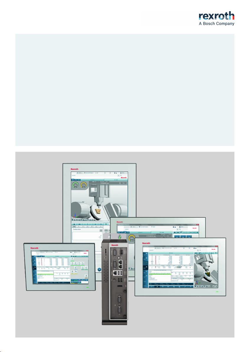
PR30 and VR30 Control Cabinet PC and
Panel PC
Bosch Rexroth AG R911384706_Edition 01