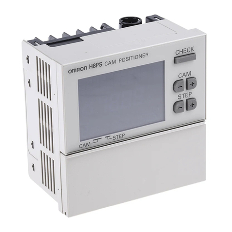
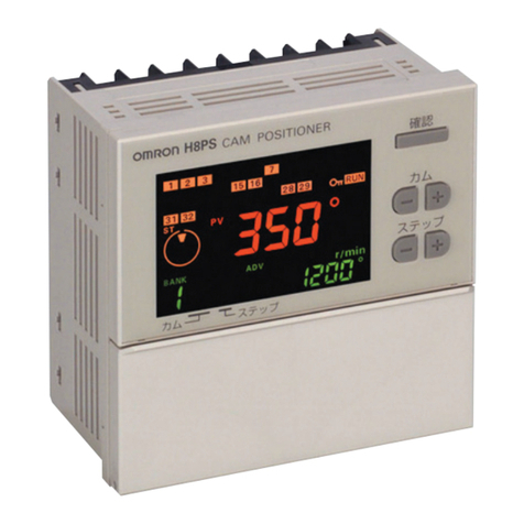
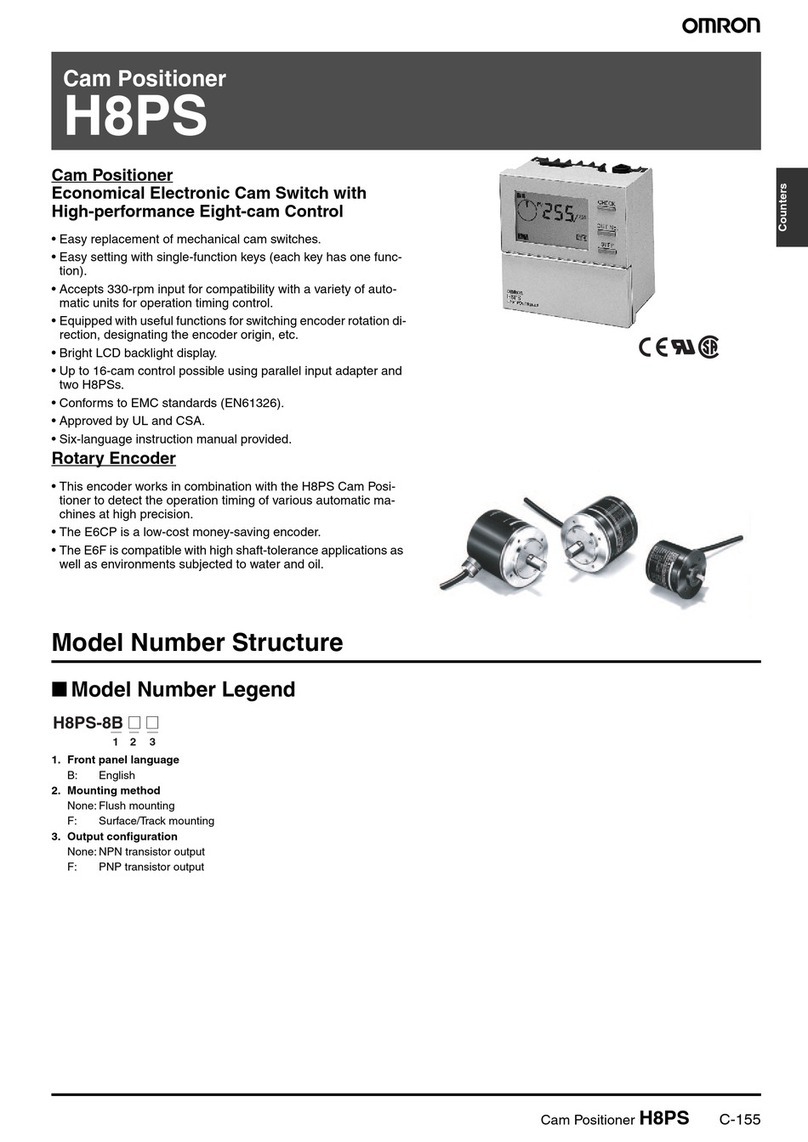
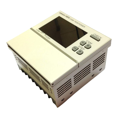
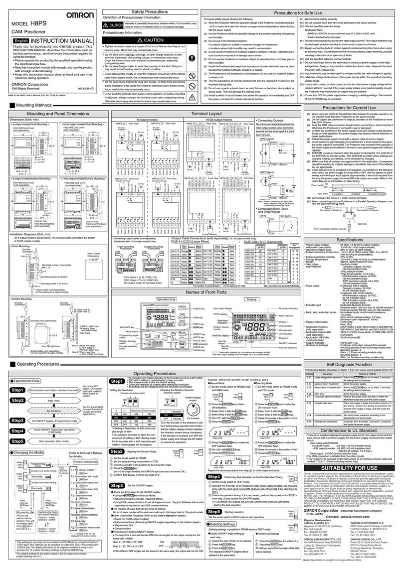
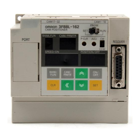
Omron 3F88L-160 Instruction manual

Connection manual of XDesignerPlus external devices
1 / 12
OMRON Industrial Automation
Cam Positioner Series
3F88L-160/162
Support version
OS
Over V4.0
XDesignerPlus
Over 4.0.0.0
CONTENTS
Thank you for using "Touch Operation Panel (M2I TOP) Series" "of M2I Co. head
office. Please read this manual, and be familiar with the ways and procedures of
connecting the "TOP-external devices".
1. System configuration
Page 2
Explains the necessary appliances, setting of each appliances, cables,
available systems to access.
Select the suitable system referring to this article.
2. Selecting TOP model and external devices
Page 3
Select a TOP model and external devices.
3. Example of system settings
Page 4
Explains an example of settings for communication interface between the
devices and the relevant external terminal.
Select an example according to the system you chose in “1. System
configuration”.
4. Details of communication settings
Page 5
Explains the way of setting TOP communication.
If external settings is changed, make sure to have the identical settings of
TOP with the external device referring to this chapter.
5. Cable table
Page 8
Explains cable specifications required for access.
Select proper cable specifications according to the system you chose in “1.
System configuration”.
6. Support address
Page 9
Check available addresses to communicate with external devices referring
to this chapter.

Connection manual of XDesignerPlus external devices
2 / 12
1. Selecting TOP model and external devices
System configuration of TOP and " OMRON Corporation –CAM Positioner Series 3F88L-160/162" "is as follows.
Series
CPU
Link I/F
Communicati
on method
Systemsettings
Cable
CAM Positioner
3F88L-160/162
Communication Port
on CPU Unit
RS-232C
3.1 Example of
settings 1
( Page 4 )
5.1 Cable table
1
(Page 8)
■ Connection configuration
ㆍ1 : 1(1 TOP vs 1 external device) connection

Connection manual of XDesignerPlus external devices
3 / 12
2. Selecting TOP model and external devices
Select the external devices to connect to TOP..
Settings details
Contents
TOP
Series
Select the name of a TOP series that is to be connected to PLC.
efore downloading the settings, install the OS version specified in the table below according to
TOP series.
Series
Version name
XTOP / HTOP
V4.0
Name
Select the model name of TOP product.
External device
Vendor
Select the vendor of external devices to be connected to TOP.
Select “OMRON Industrial Automation”.
PLC
Select the model series of external devices to be connected to TOP.
Select “CAM Positioner Series 3F88L-160/162”.
Please check, in the “1. System configuration”, if the relevant external device is available to set a
system configuration..

Connection manual of XDesignerPlus external devices
4 / 12
3. Example of system settings
Settings of communication interface in TOP and “CAM Positioner” are recommended as shown below.
3.1 Example of settings 1
The system is set as below.
Details
TOP
“CAM Positioner Series“
Remarks
Serial level (port/channel)
RS-232C (COM2)
RS-232C
User settings
Station number (PLC Address)
─
0
User settings
Serial Parity bit
[BPS]
9600
User settings
Serial data bit
[Bit]
7
User settings
Serial stop bit
[Bit]
2
User settings
Serial parity bit
[Bit]
EVEN
User settings
(1) XDesignerPlus settings
After setting the below details in [Project > Project Settings], download the detailed settings using TOP tool.
■ [ Project > Project property > Project > TOP Settings > TOP Name ]
Set a communication interface of TOP tool.
–On the right window, [ HMI Setup > HMI Setup use check > Device manager ]
■ External device settings
Set options of communication driver for “CAM Positioner Series 3F88L-160/162”..
–PLC station number(PLC): The station number same as external devices

Connection manual of XDesignerPlus external devices
5 / 12
(2) External device settings
Set the function parameters of the external devices as shown below. Please refer to the User's Manual of external devices for more
detailed settings.
1. Set “Function No. b, Parameter No. 6” as “1”. Set the Parity bit 9600 bps(factory setting)
2. Switch the power of the external device “off” “on”.
3. Set “Function No. t, Parameter No. 0 “ as “0”. Slave Unit into transmission enabled mode.

Connection manual of XDesignerPlus external devices
6 / 12
4. Communication settings details
Communication settings are available at XDesignerPlus or TOP main menu. Communication settings must be identical with the
external devices.
4.1 XDesignerPlus settings details
Select [Project > Project property] to show the below window.
■ [ Project > Project property > Project > Settings > TOP Name ]
Set the communication interface of TOP tool.
–On the right window, [ HMI Setup > HMI Setup use check > Device manager ]
–On the right window, [ HMI Setup > HMI Setup use check > PLC Setup]
■ External device settings
Set options of communication driver for "CAM Positioner Series 3F88L-160/162".
■ Communication interface settings
Details
Contents
Signal level
Select a serial communication method between TOP –External devices. (COM1 supplies RS-232C
only)
Baud rate
Select a serial communication speed between TOP –External devices.
Data bit
Select a serial communication data bit between TOP –External devices.
Stop bit
Select a serial communication stop bit between TOP –External devices.
Parity bit
Select a method of checking serial communication parity bit between TOP –External devices.
Time-out [ x100 mSec ]
Set the TOP’s wait time for response from external devices at [ 0 – 5000 ] x 1 mSec
Transmission delay time [ x10
mSec]
Transmission wait time[ x10
mSec]
Set the TOP’s wait time between receiving the response from external devices – transmitting the
next command request at [0 - 5000] x 1 mSec.
PLC station number.
[0~65535]
It is the station number of the other device. Select between [ 0 –65535 ].

Connection manual of XDesignerPlus external devices
7 / 12
4.2 Setting details of TOP main menu
- When hearing the sound while resetting the power, touch 1 upper point on LCD to move to“TOP
management main” screen..
- Set the driver interface settings of TOP according to the contents; Step1 → Step2.
(You can change the settings in Step2.if you click on “TOP COM 2/1 settings” in Step 1..)
Step 1.[ PLC Setup ] –Set the driver interface.
PLC Setup
PLC station number : 00
Communication interface
Time-out : 1000 [mSec]
settings
Delay time before transmission : 0 [mSec]
TOP COM 2/1 : RS –232C , 9600 , 7 , 2 , EVEN
TOP COM 2/1 settings Communication check
Step 1–Reference.
Details
Contents
PLC station number.
[0~65535]
It is the station number of the other device. Select between [ 0 –65535 ].
Time-out [ x1 mSec ]
Set the TOP’s wait time for response from external devices at [ 0 – 5000 ] x 1 mSec.
Delay time before
transmission [ x1 mSec ]
Set the TOP’s wait time between receiving the response from external devices –transmitting
the next command request at [0 - 5000] x 1 mSec.
TOP COM 2/1
It is the interface settings of TOP for external devices.
Step 2.[ PLC Setup ] >[ TOP COM2/COM1 settings ] –Set the serial parameters of the relevant port.
port settings
* Serial communication
COM 1 port
+ COM-1 Port
communication interface
- Parity bit : 9600 [BPS]
settings
- Data bit : 7 [BIT]
- Stop bit: 2 [BIT]
- Parity bit: EVEN [BIT]
- Signal level : RS –232C
+ COM-2 Port
COM 2 port
- Parity bit : 9600 [BPS]
communication interface
- Data bit : 7 [BIT]
settings
- Stop bit: 2 [BIT]
- Parity bit: EVEN [BIT]
- Signal level : RS –232C
Step 2-Reference.
Details
Contents
Parity bit
Select a serial communication speed between TOP –External devices
Data bit
Select a serial communication data bit between TOP –External devices.
Stop bit
Select a serial communication stop bit between TOP –External devices.
Parity bit
Select a method of checking serial communication parity bit between TOP –External devices.
Signal level
Select a serial communication method between TOP –External devices.

Connection manual of XDesignerPlus external devices
8 / 12
4.3 Communication check
■Check the interface settings between external devices - TOP.
- Resetting the power of TOP, move to the menu screen by clicking on the top of the LCD window.
- Check that the settings of the port [COM 2 or COM 1] to use in [Communication settings] are the same with the settings of
external devices.
■ Check if there is an error in port communication
- Click on the “Communication check”button in PLC Setup > TOP [ COM 2 or COM 1 ]
- The diagnostics dialogue box will pop up on the screen, then judge checking status as the contents shown in the box no.3.
OK!
Normal communication settings
Time Out Error!
Abnormal communication settings
- It is an error in the settings of a TOP/external device and cable
(reference: communication check sheet)
■ Communication check sheet
- Please check the settings shown in the sheet below if there is an error in the communication connection with external terminals.
Designer Version
O.S Version
Details
Contents
check
System
configuration
CPU name
OK
NG
Port name of the other device
OK
NG
Systemconnection method
1:1
1:N
N:1
OK
NG
connectioncable
cable name
OK
NG
PLC Setup
settings station number
OK
NG
Serial Parity bit
[BPS]
OK
NG
Serial data bit
[BIT]
OK
NG
Serial Stop bit
[BIT]
OK
NG
Serial parity bit
[BIT]
OK
NG
Address range
OK
NG
TOP settings
settings port
COM 1
COM 2
OK
NG
driver name
OK
NG
Station number of the other device
Project Property settings
OK
NG
Communication check
OK
NG
Serial baud bit
[BPS]
OK
NG
Serial data bit
[BIT]
OK
NG
Serial Stop bit
[BIT]
OK
NG
Serial parity bit
[BIT]
OK
NG

Connection manual of XDesignerPlus external devices
9 / 12
5. Cable table
This Chapter introduces the cable diagram for normal communication between TOP and the relevant devices. (The cable diagram
explained in this chapter can be different from the recommended details of “OMRON Industrial Automation”)
5.1 Cable table 1
■ 1 : 1 connection
(A) XTOP COM 2 port(9pin)
XTOP COM2
Cable connection
PLC
PIN arrangement
*Note1)
Signal
name
Pin
number
Pin
number
Signal
name
PIN arrangement
*Note1)
Front View of
D-SUB 9 Pin
male(male, convex)
CD
1
1
NC
Front View of
D-SUB 9 Pin
female(female,
concave)
RD
2
2
RD
SD
3
3
SD
DTR
4
4
NC
SG
5
5
SG
DSR
6
6
NC
RTS
7
7
RS
CTS
8
8
CS
9
9
NC
*Note1) The PIN arrangement is seen at the connection area of cable connection connector.
(B) XTOP COM 2 port(15pin)
XTOP COM2
Cable connection
PLC
PIN arrangement
*Note1)
Signal
name
Pin
number
Pin
number
Signal
name
PIN arrangement
*Note1)
Front View of
D-SUB 15 Pin
male(male, convex)
CD
1
1
NC
Front View of
D-SUB 9 Pin
female(female,
concave)
RD
2
2
RD
SD
3
3
SD
DTR
4
4
NC
SG
5
5
SG
DSR
6
6
NC
RTS
7
7
RS
CTS
8
8
CS
9
9
NC
*Note1) The PIN arrangement is seen at the connection area of cable connection connector.
(C) XTOP/ATOP COM 1 port ( 6pin)
XTOP/ATOP COM 1 port
Cable connection
PLC
PIN arrangement
*Note1)
Signal
name
Pin
number
Pin
number
Signal
name
PIN arrangement
*Note1)
Front View of
D-SUB 6 Pin
male(male, convex)
1
1
NC
Front View of
MINI-DIN 9 Pin
female(female,
concave)
RD
2
2
RD
SG
3
3
SD
4
4
NC
5
5
SG
SD
6
6
NC
7
RS
8
CS
9
NC
*Note1) The PIN arrangement is seen at the connection area of cable connection connector.

Connection manual of XDesignerPlus external devices
10 / 12
6. Support address
The device which is available at TOP is as follows.
There can be a device range difference according to the module series/type of CPU. Refer to the user's manual of each CPU module.
Be careful not to be out of the address range that the relevant device supports
- Memory Area Read (RUN) : M
Address
Name
Detailed information
32 BIT available
0000
0001
Resolver
Speed
Current Resolver Speed (r/min) : 4-digit BCD
Address 0000 : Leftmost byte / Address 0001 : Rightmost byte
X
0002
0003
Present
Cam Angle
Present cam angle (in set unit) : 4-digit BCD
Address 0002 : Leftmost byte / Address 0003 : Rightmost byte
X
0004
0005
0006
0007
Cam Output
Status
Cam output status
0 : Output OFF / 1 : Output ON
Address 0007 : CAM1~8 / Address 0006 : CAM9~16
Address 0005 : CAM 17~24 / Address 0004 : CAM 25~32
X
0008
Executing
Bank
Executing bank NO. : 2-digit BCD
○*Note1)
*Note1)The 8 digits can be read when the M0008 address uses 32BIT device.
- Parameter Area Read / Write (SET) : P
Address
Name
Detailed information
32 BIT available
0000
Resolution /
Compensation
Settings
Resolution selection, and the presence or absence of backlash and advance angle
compensations.
○*Note1)
0002
0003
Origin
Compensation
value
Origin compensation value : 4-digit BCD from 0000 to 0359 (0719)
Address 0002 : Leftmost byte / Address 0003 : Rightmost byte
X
0004
0005
Backlash
Compensation
value
Backlash compensation value : 4-digit BCD from 0000 to 0359 (0719)
Address 0004 : Leftmost byte / Address 0005 : Rightmost byte
X
0006
0007
0008
0009
Advance Angle
Compensation
Value 1
Advance angle compensation value 1 : 4-digit BCD
Address 0006, 0007 : Speed data 0000 to 1600 (0800)
Address 0008, 0009 : Angle data 0000 to 0359 (0719)
X
000A
000B
000C
000D
Advance Angle
Compensation
Value 2
Advance angle compensation value 2 : 4-digit BCD
Address 000A, 000B : Speed data 0000 to 1600 (0800)
Address 000C, 000D : Angle data 0000 to 0359 (0719)
X
000E
000F
Advance Angle
Compensation
Value 3
Advance angle compensation value 3 : 4-digit BCD from 0000 to 0359 (0719)
Address 000E : Leftmost byte / Address 000F : Rightmost byte
X
0010
0011
0012
0013
Bank 1 Cam
Data Protect
Setting
Cam data protect setting
0 : Not protected / 1 : Protected
Address 0013 : CAM1~8 / Address 0012 : CAM9~16
Address 0011 : CAM 17~24 / Address 0010 : CAM 25~32
X
0014
0015
0016
0017
Bank 1 One-
direction
Function Setting
One-direction function setting
0 : OFF / 1 : ON
Address 0017 : CAM1~8 / Address 0016 : CAM9~16
Address 0015 : CAM 17~24 / Address 0014 : CAM 25~32
X
0018
0019
001A
001B
Bank1 Rotation
Direction Setting
Rotation direction setting
0 : Forward / 1 : Reverse
Address 001B : CAM1~8 / Address 001A : CAM9~16
Address 0019 : CAM 17~24 / Address 0018 : CAM 25~32
X

Connection manual of XDesignerPlus external devices
11 / 12
Address
Name
Detailed information
32 BIT available
0020
to
002B
Bank2
Same as for bank1
Address 0020 to 0023 : Bank 2 cam data protect setting
Address 0024 to 0027 : Bank 2 one-direction function setting
Address 0028 to 002B : Bank 2 rotation direction setting
X
0030
to
003B
Bank3
Same as for bank1
Address 0030 to 0033 : Bank 3 cam data protect setting
Address 0034 to 0037 : Bank 3 one-direction function setting
Address 0038 to 003B : Bank 3 rotation direction setting
X
0040
to
004B
Bank4
Same as for bank1
Address 0040 to 0043 : Bank 4 cam data protect setting
Address 0044 to 0047 : Bank 4 one-direction function setting
Address 0048 to 004B : Bank 4 rotation direction setting
X
0050
to
005B
Bank5
Same as for bank1
Address 0050 to 0053 : Bank 5 cam data protect setting
Address 0054 to 0057 : Bank 5 one-direction function setting
Address 0058 to 005B : Bank 5 rotation direction setting
X
0060
to
006B
Bank6
Same as for bank1
Address 0060 to 0063 : Bank 6 cam data protect setting
Address 0064 to 0067 : Bank 6 one-direction function setting
Address 0068 to 006B : Bank 6 rotation direction setting
X
0070
to
007B
Bank7
Same as for bank1
Address 0070 to 0073 : Bank 7 cam data protect setting
Address 0074 to 0077 : Bank 7 one-direction function setting
Address 0078 to 007B : Bank 7 rotation direction setting
X
0080
to
008B
Bank8
Same as for bank1
Address 0080 to 0083 : Bank 8 cam data protect setting
Address 0084 to 0087 : Bank 8 one-direction function setting
Address 0088 to 008B : Bank 8 rotation direction setting
X
0100
Clear Command
Program Clear, Parameter Clear, and Parameter Update
X
1000
to
12CF
Cam Programs
for Cams1 to 8
of Bank 1
Program status
0 : Output OFF / 1 : Output ON
Address 1000 : Cam 1~8 angle 0 state ▪▪▪ Address 12CF : Cam 1~8 angle 719 state
X
1300
to
15CF
Cam Programs
for Cams9 to 16
of Bank 1
Program status
0 : Output OFF / 1 : Output ON
Address 1300 : Cam 9~16 angle 0 state ▪▪▪ Address 15CF : Cam 9~16 angle 719 state
X
1600
to
18CF
Cam Programs
for Cams17 to
24 of Bank 1
Program status
0 : Output OFF / 1 : Output ON
Address 1600 : Cam 17~24 angle 0 state ▪▪▪ Address 18CF : Cam 17~24 angle 719 state
X
1900
to
1BCF
Cam Programs
for Cams25 to
32 of Bank 1
Program status
0 : Output OFF / 1 : Output ON
Address 1900 : Cam 25~32 angle 0 state ▪▪▪ Address 1BCF : Cam 25~32 angle 719 state
X
2000
to
2BCF
Cam Programs
for Bank 2
Same as for Bank 1
X
3000
to
3BCF
Cam Programs
for Bank 3
Same as for Bank 1
X
4000
to
4BCF
Cam Programs
for Bank 4
Same as for Bank 1
X
500
to
5BCF
Cam Programs
for Bank 5
Same as for Bank 1
X

Connection manual of XDesignerPlus external devices
12 / 12
Address
Name
Detailed information
32 BIT available
6000
to
6BCF
Cam Programs
for Bank 6
Same as for Bank 1
X
7000
to
7BCF
Cam Programs
for Bank 7
Same as for Bank 1
X
8000
to
8BCF
Cam Programs
for Bank 8
Same as for Bank 1
X
*Note1)The 8 digits of data can be read when the P0000 address uses 32BIT.
- Controller Status Read (RUN, PRGM, SET) : S
Address
Name
Detailed information
32 BIT available
-
Status Read
bit 0 : Executing Status ( 0 –When an error occurs in Run mode or PRGM or
SET mode is entered
1 –When there is no error in RUN mode)
bit 6 : (1 - When the Communications function is being executed to change
the operating state)
bit 7 : (1 –When an error occurs)
X
Other manuals for 3F88L-160
1
This manual suits for next models
1
Table of contents
Other Omron Valve Positioner manuals
Popular Valve Positioner manuals by other brands

Samson
Samson 3785 series Mounting and operating instructions

EBRO ARMATUREN
EBRO ARMATUREN EP 501 B quick start

Bancroft
Bancroft TT-500 Operation manual

Siemens
Siemens SITRANS VP300 operating instructions

Burkert
Burkert Positioner TopControl Basic 8696 quick start guide

Samson
Samson 3780 series Mounting and operating instructions