Unox U-EPRSeries User manual

Electro-pneumatic Positioners
U-EPR Series
USER'S MANUAL
Ver 1.02

Electro-Pneumatic Positioners
Table of Contents
Introduction 2
Manufacturer Warranty 2
Product Description 3
Main Features and Functions 3
Operation Logic 3
Label Description 3
Suffix Symbols 4
Specification 5
Parts and Assembly 6
Dimensions 6
Installation 7
Safety Warning 7
Tools for Installation 7
U-EPR Installation 7
Using Brackets to Install 8
Connection 11
Connection - Piping 11
Power Connection - Explosion-Proof Type 12
Adjustment 14
Adjustment - Zero Point 14
Adjustment - Span 14
Adjustment - Auto/Manual Switch 15
Adjustment - Seat Adjuster 15
Adjustment - Orifice 16
Maintenance - Pilot Valve 16
Troubleshooting 17
- 1-

Electro-Pneumatic Positioners
Product Description
Main Features and Functions
It is designed for high durability and performance in high vibration environment.
Durability has proven after testing of 1 million times minimum.
Response time is very short and accurate.
Simple part change can set 1/2 SplitRange.
It is economical due to lessair-consumption.
Direct/Reverse action can be set easily.
Zero & Span adjustment process is simply.
Feedback Connection is easy.
Operation Logic
- 3-
<Figure 1>
If supply pressure increased, Flapper(②) gets pushed by the force from torque-motor(①). As
the gap between flapper(②) and the nozzle(③) increases, air pressure exhausts from
pilot valve(④) and upper spool(⑤). As a result, spool(⑤) rises. Then the air pressure
will be supplied to the actuator(⑩). As actuator(⑩) moves, the cam(⑭) receives
the
movement. This movement pulls the span spring(⑮). <Figure1>
Label Description
Model Number:
Explosion Proof:
Input Signal:
Ambient Temperature:
Supply Pressure:
Serial Number:
Indicates model name and any options (if any).
Indicates explosion proof grade.
Indicates current input signal range.
Indicates ambient temperature for normal operation.
Indicates the range of supply pressure.
Indicates unique serial number.

Electro-Pneumatic Positioners
Suffix Symbol
U-EPR series follows suffix symbols as follows.
U-EPR
════════════════════════════════
Motion Type S : Single
D : Double
════════════════════════════════
- 4-
Explosion Proof m : ExdmIIBT5
C : ExdmIICT5
i : ExiaIIBT6 or ExiaIICT6(NEPSI)
n : Non-Explosion
════════════════════════════════
Feedback Lever 1 : M6X40L
2 : M6X63L
3 : M8X40L
4 : M8X63L
5 : NAMUR
════════════════════════════════
Orifice 1 : Ø1
2 : Ø2
3 : None
════════════════════════════════
Connection Type 1 : PT
2 : NPT
════════════════════════════════
Ambient Temperature S : -20 ~ 70℃
H : -20 ~ 120℃L
: -40 ~70℃
════════════════════════════════
Option 1 0 : Standard
1 : Dome Indicator
════════════════════════════════
Option 2 1 : None
2 : + PTM Internal
3: + PTM External (explosion proof) 3 :
+ L/S Internal
4 : + L/S External (explosion proof) 5
: + PTM + L/SInternal
6 : + PTM + L/S External (explosion proof)
════════════════════════════════
* For special specification, please contact our salesdepartment.

Electro-Pneumatic Positioners
Category U-EPR
Single Double
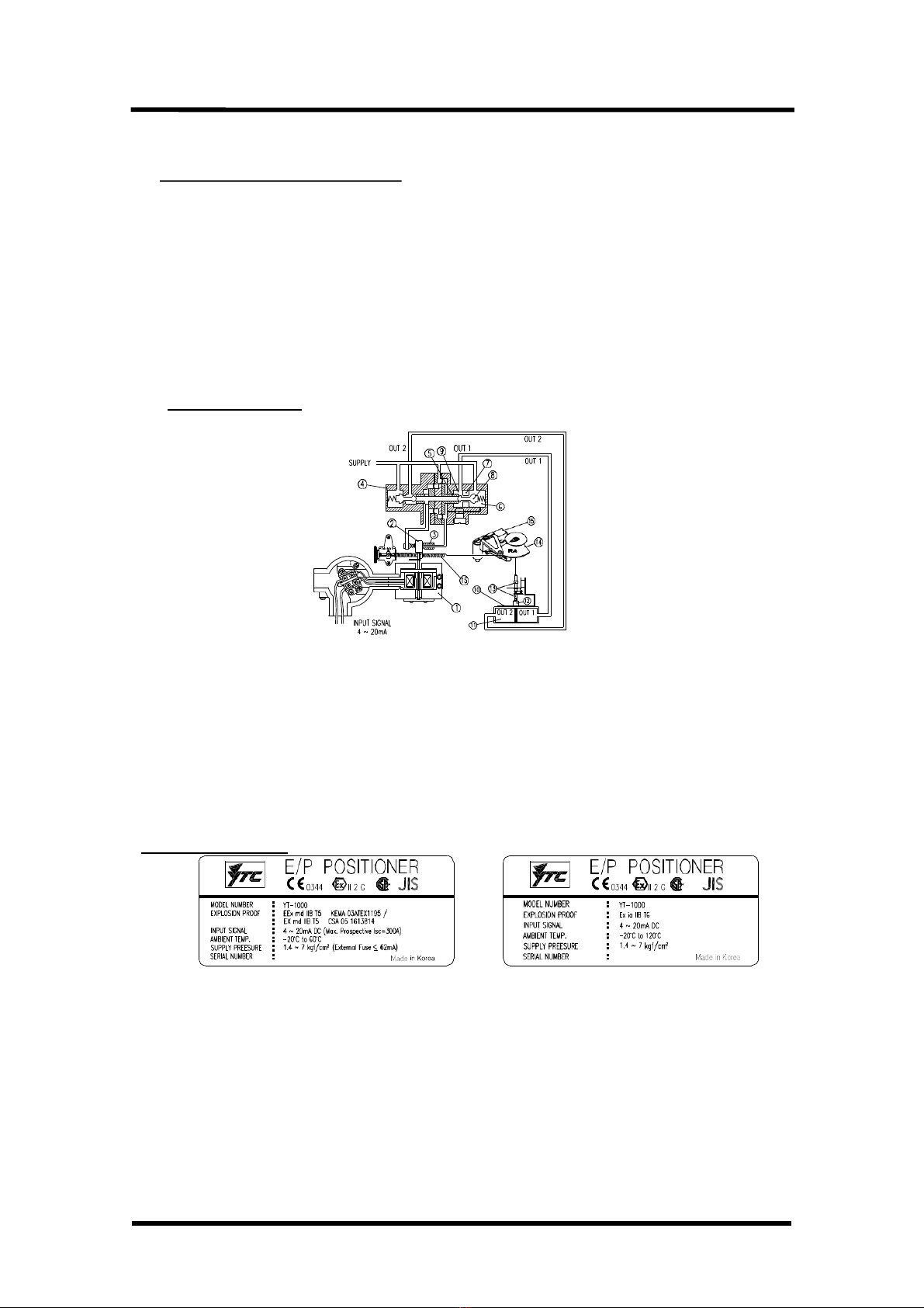
Input Signal 4~20mA DC *1
Impedance 250±15Ω
Supply Pressure 1.4~7.0kgf/cm2(20~100 psi)
Stroke 0~900 *2
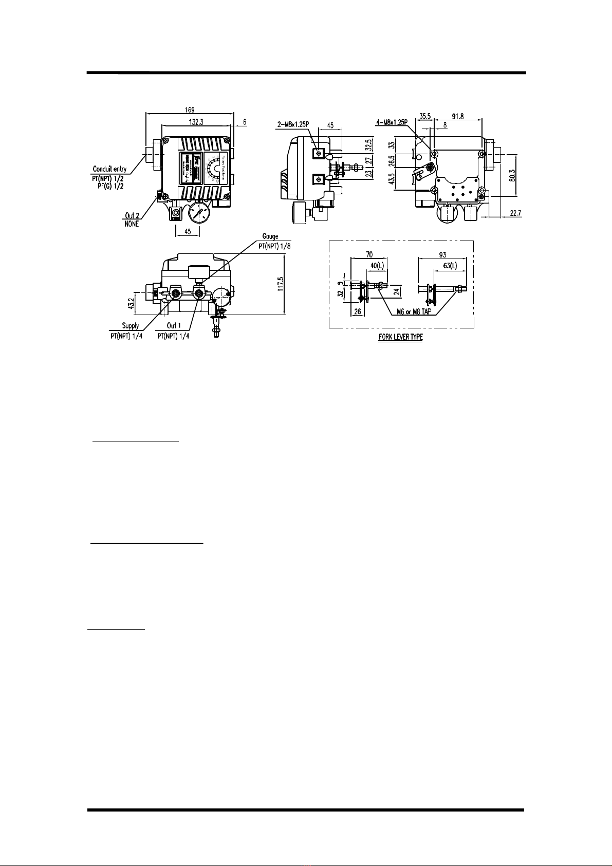
Air Connection PT(NPT) 1/4
Gauge Connection PT(NPT) 1/8
Conduit Entry PF 1/2 or G 1/2
Explosion Proof *3
Domestic: ExdmIIBT5, ExdmIICT5, ExiaIIBT6
ATEX: EExmdIIBT5, JIS : ExsdIIBT5
CSA : ExmdIIBT5, NEPSI : ExiaIICT6
Protection IP66
Ambient
Temperat
ure
Operating Standard:-20∼70℃,
Low: -40∼70℃High: -20∼120℃
Explosion -20~60℃(T5), -20~40℃(T6)
Linearity ±1.0% F.S
Hysteresis 1.0% F.S
Sensitivity ±0.2% F.S ±0.5% F.S
Repeatability ±0.5% F.S
Air Consumption 3LPM (Sup=1.4kgf/cm2,20psi)
Flow Capacity 80LPM (Sup=1.4kgf/cm2,20psi)
Material Aluminum Diecasting
Weight 2.7kg(6.1lb)
- 5-
Specification
*Tested under ambient temperature of 20℃, absolutepressureof 760mmHg, and humidityof 65%.
Please contact us formoredetailed specification.
*1: For 1/2 Split Control,it can be applied by adjustingzero andspan.
*2: For inquiryregarding strokes under 10mm or above 150mm,
* U-EPR has differenttypes of explosionproofcertificates. Please make sure to check explosionproof
grade.

Electro-Pneumatic Positioners
Parts and Assembly
- 6-
Dimensions
<
Explosion-prooftype U-EPR >

Electro-Pneumatic Positioners
<Intrinsically safe type U-EPR >
Installation
Safety Warning
When installing positioner, please ensure to read and follow safety instruction.
All input and supply pressure to valve, actuator, and other related devices must be turned
off.
Use bypass valve or other equipment to avoid entire system "shut down."
Make sure there is no remaining pressure in the actuator.
Tools for installation
①Hexagonal wrench
②Screw drivers (+) & (-)
③Spanners for hexagonal-head bolts
installation
U-EPR should be installed on rotary motion valve such as ball valve or butterfly valve
- 7-
Before installation, be sureto
using spring return type diaphragm or piston actuator. check
for following installation components.
①U-EPR main body
②Feedback lever and lever spring
③Flange nut
④4 pcs. of hexagon head bolts (M8 X 1.25P)
⑤4 pcs. of M8 platewasher

Electro-Pneumatic Positioners
Installation Steps
- 8-
<Figure 2: Using Fork TypeLever> <Figure 3: Using NAMUR Shaft>
Using Bracketsto Install
U-EPR is provided with standard bracket. This bracket contains three parts, and
brackets can be used for both fork type lever and NAMUR Shaft.
<Figure 4: Assembly Methodby stem height "H">
1) In general, the height of an actuator (H) is 20, 30, or 50mm. Please check using
acutator stem height and assemble bracket according to <Figure 4>.
Stem Height (H)
Actuator
<Figure 5: Measuring Stem Height(H)>

Electro-Pneumatic Positioners
2) Attach bracketed U-EPR to the actuator by using hexagon-headed and wrench bolts. Size
of the bracket hole is 6mm. When tightening bolts, use spring washer or
similar for firm attachment to the actuator, so U-EPR will not shake by vibration or any other
impact. The direction of bracket is different by the operating condition, but normally, the
positioner is installed as shown in <Figure 6>.
- 9-
<Figure 6>
3) Set rotation position of the actuator stem at zeropoint, "0%". For a single type of
actuator, it is easy to check zero point, because the actuator stem is positioned at zero point
when there is no supply pressure. If double acting actuator is used, check
actuator stem's rotation direction (clockwise or counter-clockwise) by supplying pressure.
4) Install the fork lever as shown in <Figure 7> after setting actuator stem at zero point. Check
the direction of the actuator stem - clockwise or counter-clockwise. Installation angle of the
fork lever should be 45 degrees based on the linear shaft. For NAMUR shaft, the angle does
not matter.
Counter-Clockwise Clockwise
<Figure 7>

Electro-Pneumatic Positioners
5) After setting fork lever position, lock nuts which are assembled on the bottom of the fork lever.
Make sure to set upper height of the fork lever between 6-11mm, which is lower than upper
bracket height. <Figure8>
6-11mm
Fork Lever Actuator
<Figure 8>
6) Attach YT-1000R to the bracket. Fix the clamping pin on the main shaft's center of U-EPR and
insert connection bar into the fork lever slot, so it can be locked to the fork lever spring. This
sets the alignment of the main shaft of U-EPR and center of the actuator stem.
Bad alignment of the main shaft and the actuatorstem lowers U-EPR
s durability, because too much force will be on the main shaft of U-EPR.
<Figure 9>
<Figure 9>
7) Tighten U-EPR base and the bracket with hexagon-headed bolts and plate washer. It is
recommended to tighten four bolts after checking U-EPR 's position. <Figure 10>
<Figure 10>
-10 -

Electro-Pneumatic Positioners
Connection
Connection- Piping
Note
To avoid entering moisture, oil, or dust into
selection of supply pressure compressor.
-11 -
the product, please carefully make
It is recommended to attach air filter regulator before supply port of U-EPR.
SupplyPressure Condition
①Dry air with at least 10℃lower than ambient temperature.
②Avoid from dusty air. Filter can only sort 5 micron or larger.
③Avoid any oil.
④Comply with ANSI/ISA-57.3 1975(R1981) or ISAS7.3-1975(R1981).
⑤Not to be used beyond the range of 1.4 - 7 kgf/㎠(140 - 700 kPA).
⑥Set air filter regulator's supplied pressure 10% higher than actuator's spring range
pressure.
Pipe Connection
①Make sure inside of pipe isemptied.
②Do not use pipeline that is squeezed or has hole.
③To maintain flow rate, use the pipeline that has more than 6mm inner diameter.
(10mm outer diameter)
④Do not use extremely long pipeline system. It may affect flow rate due to the friction
inside of the pipeline.
Piping Connection with Actuator
Singleacting actuator
U-EPR series single acting type is set to use OUT1 port. OUT1 port should be connected
with supply pressure port from actuator when using single acting type of spring return
actuator. <Figure 11>
<Figure 11> <Figure 12>

Electro-Pneumatic Positioners
Doubleacting actuator
For U-EPR series double acting type, when inputting current signal, supply pressure is out
from OUT1. Please refer to <Figure 12>
-12 -
<Figure 13: Cam adjustmentand piping connection>
Power Connection - Explosion-Proof Type
Connection - Connection Port
(1) Connection port size is PF1/2 or G1/2.
(2) Make sure that the fastener bolts is tightly fastened.
(3) Make sure to seal tightly on the connection port, and
there is no leak.
(4) When connecting explosion-proof type terminal,
the number of thread must be at least six and has to
be water-proof. <Figure 14>
<Figure 14>

Electro-Pneumatic Positioners
Connection - Cable Gland
①Use certified explosion proof products.
②End of cable must be crimpstyle terminal. Please refer to below table. <Figure 15>
-13 -
<Figure 15>
③Insert the terminal connection into terminal box and lock completely.
④Insert washer and rubber packing, and fasten the cable gland completely.
⑤Fasten the clamp, then Union Grouping andUnion Cover. <Figure 14>
Connection - Power
①Open terminal box cover.
②Locate the poles and connect them properly.
Make sure to fasten the connection.
③Close back the terminal box cover. <Figure
16>
<Figure 16>
Safety Warning
YT-1000R designedunder intrinsicallysafe proceduresand restriction.However,
intrinsicallysafe system can be damaged from electronic energiesfrom other
electronic devices.To avoidany system damages,pleaseread the following.
Differentiateintrinsicallysafe type circuitwithother types of circuit clearly.
Apply properprotectiondeviceto reduce frictions.
If possible, minimize theuseof inductance and capacitance. If they must be used,
set the devicesat lowerlevel than the maximum level.
Protect thewiresfrom damages.
Grounding must be done properly according to thefield's procedures.

Electro-Pneumatic Positioners
Connection - Ground
①Open positioner's body cover.
②Locate the poles and connect them
properly. <Figure 17>
-14 -
<Figure 17>
Adjustment
Adjustment - Zero Point
①Set supply signal at 4mA or 20mA and rotate
adjuster clockwise or counter-clockwise to adjust
actuator's initial point. When setting initial point, the
specification of valve and system must be taken
account. Please refer to <Figure 18> for
increase/decrease of the zero point.
<Figure 18>
②When single acting actuator with spring is used, please check if the pressure level which
is indicated on the positioner is same to the supplied pressure level.
Adjustment - Span
①After setting zero, supply 20mA or 4mA of
signal. Check the actuator's stroke. If the stroke
is too low, adjust the span towards '+' direction.
On the other hand, if the stoke point is too high,
adjust the span towards '-' direction. <Figure
19>
②Changing span point affects zero point setting.
So zero setting must be set again. After
setting zero point, confirm the span point. This
step must be repeated until both points are
properly set.
③After setting is completed, tighten Lock Screw. <Figure 19>
<Figure 19>

Electro-Pneumatic Positioners
Adjustment - A/M Switch (Auto/Manual)
①A/M switch adjusts the valve operation to
automatic or manual.
②When produced, U-EPR is set at "A(Automatic)".
If user prefers the positioner's setting as
"M(Manual)," the setting can be changed by
turning the switch
counter-clockwise. <Figure 20>
③If it is set as "M(Manual)", the air pressure will be
supplied to the actuator directly. Always
set back to "A(Automatic)" after setting change.
④If OUT2 in single acting actuator or double
acting actuator is used, A/M Switch will not operate. <Figure 20>
Adjustment - Seat Adjuster
①Seat Adjuster is set according to the customer's request before the positioner is
delivered. Please do not adjust the Seat Adjuster.
②Seat Adjuster is used for double acting actuator always and adjustedwhen the pressure
balance point must be changed. Please do not touch the Seat Adjuster, because it can
affect the positioner's performance. <Figure 21>
-15 -
<Figure 21>

Electro-Pneumatic Positioners
Adjustment - Orifice
①If the size of actuator is too small relative to the flow rate, positionercan have hunting.
In order to avoid hunting, orifice canbe used. There are three types of
the orifice.
Actuator Size Orifice Size Suffix Symbol
90 cm3 less ∅11
90 ~ 180 cm3∅22
180 cm3more none 3
-16 -
②Remove the o-ring from OUT1 and OUT2 port and insert appropriate orifice. After
inserting orifice, place back the o-ring. Make sure there is no substance entering into
port. <Figure 22>
③If hunting persists after inserting the orifice, please contact YTC or its appropriate agent.
<Figure 22>
Maintenance- Pilot Valve
Maintenance should be performed on Pilot Valve Relay at least once a year. When dissembling
the pilot valve relay, please do make sure not to loose o-ring or stabilizer spring. Please refer to
<Figure 23> for the instruction.
(1) Remove stopper bolts.
(2) Unlock the Auto/Manual Switch.
(3) Remove if there is any blocking within the port and orifice.
<Figure 23>

Electro-Pneumatic Positioners
TROUBLESHOOTING
▶Positionerdoesnot respond to theinput signal.
(4) Check supply pressure level. The lever must be at least 1.4 kgf/cm2. For
spring-return type of actuator, the supply pressure level has to be larger than the
spring's specification.
(5) Check if input signal is properly supplied to the positioner. The signal should be
4~20mA DC.
(6) Check if zero point or span point is properly set.
(7) Check if the positioner's nozzle has been blocked. Also, check if the pressure is
supplied to the positioner and the pressure is being exhausted through the nozzle. If the
nozzle has been block by any substances, please send the product for repair.
(8) Check if feedback lever has been installedproperly.
▶The pressure of OUT1 reachesexhausting pressure level and does not comeback
down.
(1) Check A/M Switch. If the switch has been damaged,replace the switch or pilot relay
valve.
(2) Check for a gap or damages between the nozzle and the flapper. If damaged,
please send the product to YTC forrepair.
▶The pressure is exhausted only by A/M Switch.
(1) Check if the positioner's nozzle has been blocked. Also, check if the pressure is
supplied to the positioner and the pressure is being exhaustedthrough the nozzle. If the
nozzle has been blocked by any substances, please send the product to YTC for repair.
▶Hunting occurs.
(1) Check if safetyspring has been displaced. (Next to Pilot relay valve)
(2) Check if the size of actuator is too small. If so, insert an orifice in order to reduce
the pressure flow rate.
(3) Check if there is any friction between the valve and the actuator. If so, increase
actuator's size or reduce the friction level.
▶Actuator only operatesby On/Off.
(1) Check actuator and positioner's acting type. Air pressure exhausts from
U-EPR 's OUT1 port as input signal level increases. Therefore, it is standard to connect
to OUT1 port when single actuator is used. Make sure the span adjustment is properly
set according to the valvesystem.
▶Linearityis too low.
(1) Check if positioner is properly positioned. Especially check if the feedback lever is parallel
to the ground at 50%point.
(2) Check if zero and span point have been properly adjusted. If either one of values is being
adjusted, another one must be re-adjusted as well.
(3) Check if supply air pressure level is stable fromthe regulator. If the level is
-17 -

Electro-Pneumatic Positioners
unstable, the regulator must be replaced.
▶Hysteresis is too low.
(1) In case of double acting actuator, check if seat adjustment has been properly
performed.Please contactYTC for any further inquiries regardingthe seat
adjustment.
(2) Backlash can occur when the feedback lever and lever spring are loosen. To avoid
backlashing, please adjust the lever spring.
(3) Check if the connection bar to the feedback lever is tightly fastened.
-18 -
Table of contents
Popular Valve Positioner manuals by other brands

Dresser
Dresser MOONEY FLOWGRID SLAM SHUT Installation, operation & maintenance manual

RTK
RTK RE 3442 Series Installation and operating instructions

Vector
Vector TCT-MZ quick start guide

Samson
Samson 3730 Series Mounting and operating instructions

Burkert
Burkert 8791 REV.2 operating instructions

M2 Antenna Systems
M2 Antenna Systems FGAE1000-D1-W-COS-A-N manual

MIEPL
MIEPL YTC YT-2600 Series product manual

tissin
tissin TS700 Series instruction manual

Parker
Parker Daedal 412LXR Series product manual

cascade corporation
cascade corporation 55K installation instructions

Bifold Orange
Bifold Orange EX200 Operation, installation, and maintenance manual

Burkert
Burkert 1067 instruction manual