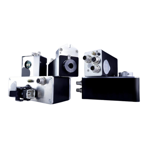
Westlock K20 User manual

WESTLOCK CONTROLS
280N MIDLAND AVENUE, STE.258, SADDLE BROOK, NJ 07663 TEL: 201-794-7650 FAX: 201-794-0913
www.westlockcontrols.com
12/20/2017 TECH-533/ D.W.O. 22902 Page 1 of 20
K20 Intrinsically Safe Valve Positioner
OPERATING MANUAL
IOM:
Tech-533
Revision: -
Prepared By:
A R Paolini
Date:
6/22/2017
Drafting Work Order: 22902
ECN: N/A
Reviewed By:
Tim Hennessey
Date:
12/20/2017
Approved By:
Jason Moorehead
Date:
12/20/2017
This IOM contains confidential information and is issued in confidence on the condition that it be returned on demand and not be copied,
reproduced, disclosed to others or used in manufacture of the subject matter thereof without the written consent of Westlock Controls

WESTLOCK CONTROLS
280N MIDLAND AVENUE, STE.258, SADDLE BROOK, NJ 07663 TEL: 201-794-7650 FAX: 201-794-0913
www.westlockcontrols.com
12/20/2017 TECH-533/ D.W.O. 22902 Page 2 of 20
Revision History
Revision
12/20/2017
Initial release
Westlock Controls Locations
USA
Phone: (201) 794-7650
Europe
Phone: +44-1892-516277
Asia
Phone: +65 676 858 00

WESTLOCK CONTROLS
280N MIDLAND AVENUE, STE.258, SADDLE BROOK, NJ 07663 TEL: 201-794-7650 FAX: 201-794-0913
www.westlockcontrols.com
12/20/2017 TECH-533/ D.W.O. 22902 Page 3 of 20
Table of Contents
1Introduction.................................................................................................................... 4
1.1 Product Certification................................................................................................ 4
1.2 Warnings ................................................................................................................. 4
1.3 Description .............................................................................................................. 5
1.4 Principles of Operation ............................................................................................ 5
1.5 Special Features....................................................................................................... 6
2Order Guide.................................................................................................................... 6
3Definitions...................................................................................................................... 8
4Installation ..................................................................................................................... 8
4.1 Mounting................................................................................................................. 8
4.2 Calibration............................................................................................................. 10
5Field Wiring .................................................................................................................. 10
6Maintenance and Repair............................................................................................... 16
7Appendix...................................................................................................................... 17

WESTLOCK CONTROLS
280N MIDLAND AVENUE, STE.258, SADDLE BROOK, NJ 07663 TEL: 201-794-7650 FAX: 201-794-0913
www.westlockcontrols.com
12/20/2017 TECH-533/ D.W.O. 22902 Page 4 of 20
1 Introduction
1.1 Product Certification
Enclosure Material
154155
17.70130633
ATEX
1725
SIRA
17ATEX2181X
IECEx
IECEx CSA 17.0012X
Resin/
Stainless Steel
Class I, Div. 1, Groups A,B,C & D, T4;
Class I, Zone 0, AEx/Exia IIC T4 Ga;
Type 4X, IP65
-40 to +85°C
II 1G
Ex ia IIC T4 Ga
Ex ia IIC T4 Ga
Aluminum
Class I, Div. 1, Groups A,B,C & D, T4;
Class II, Div. 1, Groups E,F & G; Class III;
Class I, Zone 0, AEx/Ex ia IIC T4 Ga;
Class II, Zone 21, AEx/Ex tb IIIC T87 Db;
Type 4X, IP65
-40 to +85°C
II 1G/II 2D
Ex ia IIC T4 Ga
Ex tb IIIC T87 Db
Ex ia IIC T4 Ga
Ex tb IIIC T87 Db
Model K20 is a 4 – 20 mA Intrinsically Safe Valve Position Controller.
Rated 30 V dc, 100 mA, 0.75 W max. Temperature Code T4, Ambient working temperature range
of –40 to +85OC, Type 4X / IP 65.
The unit must be installed as per the control drawing WD-12316 (see appendix A).
This unit may be equipped with either two 3-wire switches or two 2-wire inductive sensors.
1.2 Warnings
WARNING: The aluminum housing Model K20 Ex ia is at potential risk of ignition by impact or
friction therefore, care must be taken into account during installation to avoid this problem.
AVERTISSEMENT : Modèle K20 ia contient en aluminium et est à un risque d’inflammation par
choc ou frottement.
Il faut en compte lors de l’installation pour éviter ce problème.
Wires must be rated at least 105°C with minimum 0.25mm thickness shall be used for external
connections.
Fils doivent être évaluées au moins 105°C minimum 0,25 mm d’épaisseur doivent être utilisés
pour les connexions externes.
WARNING: POTENTIAL ELECTROSTATIC CHARGING HAZARD- Clean the equipment only with a
damp cloth to prevent static charge build-up on the resin enclosure or beacon.
AVERTISSEMENT : Potentiel électrostatique de charge dange - Clean l’équipement uniquement
avec un chiffon humide pour empêcher statique charger l’accumulation sur l’enveloppe de
résine ou la balise.
ATTENTION: Maximum supply pressure is 120 PSI. Supply air must be clean, dry, oil free
instrument air per ANSI / ISA-7.0.01- 1996 or BS ISO 8573-1:2010.

WESTLOCK CONTROLS
280N MIDLAND AVENUE, STE.258, SADDLE BROOK, NJ 07663 TEL: 201-794-7650 FAX: 201-794-0913
www.westlockcontrols.com
12/20/2017 TECH-533/ D.W.O. 22902 Page 5 of 20
1.3 Description
The K20 is a 4-20mA electro-pneumatic valve positioner/controller. Position measuring
is performed by off-set, shaft driven, state of the art Hall Effect Sensor.The positioner
comes standard with 4-20mA feedback transmitter. In addition there are options for
feedback limit switches, Mechanical, proximity & inductive proximity type.
1.4 Principles of Operation
The K20 utilizes two keys for auto calibration and two keys for settings. This controls
both Positioner and Position Transmitter with local LCD in conjunction with the
Diagnostic / Fault LED.
The K20 uses Hall Effect position sensing with ‘off axis’ detection to allow a through shaft
for the top mounted Westlock Beacon.
Arrow
Keys
Fault LED
Calibration
keys

WESTLOCK CONTROLS
280N MIDLAND AVENUE, STE.258, SADDLE BROOK, NJ 07663 TEL: 201-794-7650 FAX: 201-794-0913
www.westlockcontrols.com
12/20/2017 TECH-533/ D.W.O. 22902 Page 6 of 20
1.5 Special Features
Front panel
oLCD to show alphanumeric characters (8 digit 14 segment)
oDiagnostic / Fault - Red LED
Auto Calibration
Direct and reverse acting (set for low or high loop current closes valve)
Transmitter will output 4mA for valve closed, 20mA for valve open with current
Increasing linearly with opening percentage.
Two switch calibration for 4mA and 20mA without need to set loop currents
Low position calibration
High position calibration
Auto tuning automatically selects loop parameters for best operation
Allowed range of actuators in terms of open/close times
250ms to 2 – 10 minutes, upper limit can be adjusted via Long CAL
Manual tuning
oSet Drop Off on/off
oSet Gain, Zero and Span positions
oLCD displays loop current, valve position.
Integrated Transmitter
The transmitter operates from the same sensor input as the main unit, but is powered by
a separate loop. It shows the current position of the valve by sinking between 4mA and
20mA with 4mA being 0% open and 20mA being 100% open.
If the main section of the K20 fails and so ceases to provide position updates to the
Transmitter or the position sensor fails on the main section, so that the current valve
position is unknown, the Transmitter will put out a current of 3.5mA or 21.5mA
(selectable), to indicate this failure. This “fail” current will be put out within 200ms of the
actual failure. If the main unit detects an error >10% of position, the transmitter will
output fault current and the Fault LED starts blinking.
Open/close Limit Switches
These are optional SPDT Mechanical, SPDT Magnum or NAMUR Inductive proximity
sensors.

WESTLOCK CONTROLS
280N MIDLAND AVENUE, STE.258, SADDLE BROOK, NJ 07663 TEL: 201-794-7650 FAX: 201-794-0913
www.westlockcontrols.com
12/20/2017 TECH-533/ D.W.O. 22902 Page 7 of 20
2 Order Guide
K20
|
|S
|D
|N
| |
| | IS
|||
|||E
|||S
|||A
||||
||||H
||||L
||||V
|||||
|||||0
|||||1
||||||
||||||B
||||||C
||||||D
|||||||
|||||||0
|||||||B
|||||||I
|||||||T
|||||||
R
||||||||
||||||||B
|||||||||
|||||||||N
|||||||||B
|||||||||F
|||||||||S
||||||||||
VVVVVVVVVV
K20 NIS E H 0 C R B F
Magnum Proximity Switch Application Note:
For 24 VDC service below 1 watt, R (Rhodium Magnum switches) is recommended
For 24 VDC service above 1 watt, T (Tungsten Magnum switches) is recommended
*Consult Sales for multiple conduit offerings.
**
Mounting Pattern (M8 x 1.25 Outer Pattern) (M6 x 1 Inner Pattern)
*** Mounting Pattern (5/16 - 18 Outer Pattern) (M6 x 1 Inner Pattern - Metal Housing only)
Housing Material
Engineered Resin Enclosure (ClearCover w/Visible LCD)
316 Stainless Steel CF8M(Adder for 316SS Manifold also required)
(1) 3/4-14 NPT*** (Recommended with switch options)
(1)M25 x 1.5 ** (Recommendedwith switch options)
Anodized Aluminium
Stainless Steel (Required for 316SS Enclosure)
Aluminum Enclosure
Supply Pressure
STD flow Low Pressure (15 - 45 psi)
High Flow (40 - 120 psi,for larger actuators)
Manifold Material
STD flow High Pressure (40 - 120 psi)
= Model number: K20NISEH0CRBF
2 xSPDTMagnum Proximityswitches with Tungsten Contacts
2 xInductive Sensors P&FModel NJ2-V3-N
2 xSPDTMechanical Switches with Gold Plated Contacts
( Not Suitable for Class I,Div2 )
1/4" NPTw/ Stainless Steel Filter-Regulator
Assembly(Notavailable with High Flow option)
2 xSPDTMagnum Proximityswitches with Rhodium contacts
1/4" NPTw/Aluminum Filter-Regulator
Assembly(3/8"NPTwith High Flow option)
1/4" BSP (3/8" BSP with high flow option)
Conduit Entry *
Limit Switch Options
None
Position Transmitter Output
4-20mATransmitter
Pneumatic Connections
1/4" NPT (3/8" NPT with high flow option)
(1)M20 x 1.5 **
ELECTRO-PNEUMATIC POSITIONER
IntrinsicallySafe and Non-Incendive
KSeries Positioner (IntrinsicallySafe and Non-Incendive)
SEE DATASHEET FOR HAZARDOUS RATINGS OF BASE MODELS
Base Model
Electro-Pneumatic Positioner ( 4-20 mAInput )
Hazardous Area Certification
Shaft Output
Standard (Double-D with 1/4"Flats)
Direct mount to Keystone 79U orMRP Actuators
NAMUR

WESTLOCK CONTROLS
280N MIDLAND AVENUE, STE.258, SADDLE BROOK, NJ 07663 TEL: 201-794-7650 FAX: 201-794-0913
www.westlockcontrols.com
12/20/2017 TECH-533/ D.W.O. 22902 Page 8 of 20
3 Definitions
4 Installation
4.1 Mounting
Choice of Mounting:
Figure 1
Mounting for Shaft Output Options Standard and Namur
Actuator
Coupler
(Not required for Namur
option)
Bracket

WESTLOCK CONTROLS
280N MIDLAND AVENUE, STE.258, SADDLE BROOK, NJ 07663 TEL: 201-794-7650 FAX: 201-794-0913
www.westlockcontrols.com
12/20/2017 TECH-533/ D.W.O. 22902 Page 9 of 20
Figure 2
Mounting for Shaft Option Direct Mount to Keystone 79U or MRP Actuators
4.2 Pneumatic piping:
Single Acting Actuator (Spring Return):
For single acting actuators Outlet Port 2 is to be plugged. Outlet Port 1 is to be piped to the
actuator inlet port that acts against the spring. (Increasing signal causes pressure to increase in
Outlet Port 1 of the positioner).
Double Acting Actuator (Double Return):
For double acting actuators Outlet Port 2 is piped to drive the actuator towards the fail
Position. Outlet Port 1 is piped to drive the actuator away from the fail position.
(Increasing Signal causes pressure to increase in Outlet Port 1 of the positioner and pressure to
Decrease in Outlet Port 2 of the positioner
Figure 3 Standard Flow Manifold Figure 4High Flow Manifold
Actuator
Mod Mount
Bracket
(Included with D option)

WESTLOCK CONTROLS
280N MIDLAND AVENUE, STE.258, SADDLE BROOK, NJ 07663 TEL: 201-794-7650 FAX: 201-794-0913
www.westlockcontrols.com
12/20/2017 TECH-533/ D.W.O. 22902 Page 10 of 20
4.3 Calibration
There are 3 auto calibrate modes (all modes auto calibrate the Transmitter)
oAuto Calibration for 4mA to 20mA.
oCalibration for Low current calibration other than 4mA.
oCalibration for High current calibration other than 20mA.
4.3.1 Auto Calibration for 4mA to 20mA operation
This is a two Key auto calibration that defines 4mA for the valve being fully closed and
20mA for valve being fully open. The Transmitter Function is being automatically
calibrated during this procedure.
Time for the first move in calibration will be set at a maximum of 30 seconds for REG CAL
and all subsequent time outs are keyed off the time it takes to go from closed to open, to
create much shorter subsequent time outs for smaller valves. The initial 2 minute time
out can be lengthened in the Manual Calibration routine Long CAL.
Press SEL Key until the Display shows “AUTO CAL” then press Key.
Auto calibration will occur for 4mA low current and 20mA high current.
The display will show:
AUTO CAL
STARTED
LOW CAL The valve is closed and the closed position recorded.
HIGH CAL The valve is opened and the open position recorded.
GAIN The valves best gain setting is found.
CALIBRATION SUCCESS
XX % Percent valve opening for forward acting / closing for reverse acting.
4.3.2 Auto Calibration for Low current Calibration other than 4mA (Split Range)
The Low calibration refers to the input current value that drives the valve into the fail
position.
The Transmitter Function is being automatically calibrated during this procedure.
First follow the procedure for the Auto Calibration
Next set loop current to the desired value.
Press the SEL Key until the display shows “LO CAL” then press Key.
The calibration will adjust to the desired low current.

WESTLOCK CONTROLS
280N MIDLAND AVENUE, STE.258, SADDLE BROOK, NJ 07663 TEL: 201-794-7650 FAX: 201-794-0913
www.westlockcontrols.com
12/20/2017 TECH-533/ D.W.O. 22902 Page 11 of 20
4.3.3 Auto Calibration for High current Calibration other than 20mA (Split Range)
High calibration refers to the input current value that drives the valve into the Span
position.
The Transmitter Function is being automatically calibrated during this procedure.
First follow the procedure for the Auto Calibration
Next set loop current to the desired Span value.
Press the SEL Key until the display shows “HI CAL” then press Key.
The calibration will adjust to the desired high current.
4.4 Manual Calibration
This allows setting of all parameters.
Note - Adjustments take immediate effect.
All Manual Calibration Steps will timeout after 2 minutes, discarding any changes if no
key is pressed during that time.
At the end of any procedure, changes can be kept by saving the changes.
To Save the changes press and hold the Key until the display shows:
HOLD
TO SAVE
SAVED Changes made to this point are saved.
Or you can Exit without saving, this discards the changes that were entered.
To enter Manual Calibration, Press the SEL Key until MAN CAL is shown on the the display
will show FWGN xx.
Repeatedly pressing the SEL switch will cycle through what can be changed.
FWGN xx
RVGN xx
DR ENABL or DR DISAB based upon what is set
ZERO xx
SPAN xx
DIR ACTG or REV ACTG based upon what is set
TX FT LO or TX FT HI based upon what is set
REG CAL
RESTORE FACTORY DEFAULT

WESTLOCK CONTROLS
280N MIDLAND AVENUE, STE.258, SADDLE BROOK, NJ 07663 TEL: 201-794-7650 FAX: 201-794-0913
www.westlockcontrols.com
12/20/2017 TECH-533/ D.W.O. 22902 Page 12 of 20
4.4.1 Forward Gain (FWGN XX) is the gain applied when opening the valve.
oThe LCD shows “FWGN xx” where xx is the current gain.
oPressing the DOWN Key decreases the gain
oPressing the UP Key increases the gain
4.4.1 Reverse Gain (RVGN XX) is the gain applied when closing the valve.
The LCD shows “FWGN XX” press the CAL Key again and the LCD shows “RVGN XX”.
RVGN xx changes can now be made.
Pressing the DOWN Key decreases the gain
Pressing the UP Key increases the gain
4.4.2 Drop off (DR ENABL or DR DISAB)-Enables or Disables Drop off at end of travel
The LCD shows “RVGN XX” press the CAL Key again and the LCD shows either “DR ENABL
or DR DISAB” . DR ENABL or DR DISAB can now be selected.
Pressing the DOWN or UP Key toggles this setting.
4.4.3 Zero Position (ZERO XX)- Adjusts the electronic stop away from (increasing values) or
towards (decreasing values) from the physical closed position. 0 being nominally the
position of the hard stop zero and 100 being about 90 degrees away from it
The LCD shows “DR ENABL or DR DISAB” press the CAL Key again and the LCD shows
“ZERO xx”. ZERO XX changes can now be made.
Pressing UP Key increases the zero position of the valve away from the hard stop.
Pressing DOWN Key moves the zero position closer to the hard stop.
4.4.4 Span Position (SPAN XX) - Adjusts the electronic stop away from (increasing values)
or towards (decreasing values) from the physical open position. 0 being nominally
the position of the hard stop Span Zero and 100 about 15 degrees away from it
Pressing DOWN Key reduces the span position of the valve away from the hard stop
Pressing UP Key moves the span position closer to the hard stop.
4.4.5 Direct / Reverse Acting (DIR ACTG / REV ACTG)-Direct Acting means that the valve
opens with increasing loop current, Reverse Acting means that it closes with increasing
loop current. This function can be selected after the auto calibration is complete.
Pressing the DOWN or UP Key toggles this setting.
4.4.6 Transmitter Fault Current (TX FT LO or TX FT HI) - This specifies the Monitor Transmitter
Fault current as either LO 3.5mA or HI 21.5mA. This is always available but only effective
if the unit has a Transmitter.
The LCD shows “DIR ACTG or REV ACTG” press the SEL Key again and the LCD shows “TX
FT LO or TX FT HI”. TX FT LO or TX FT HI can now be selected.
Pressing the DOWN or UP Key toggles this setting.

WESTLOCK CONTROLS
280N MIDLAND AVENUE, STE.258, SADDLE BROOK, NJ 07663 TEL: 201-794-7650 FAX: 201-794-0913
www.westlockcontrols.com
12/20/2017 TECH-533/ D.W.O. 22902 Page 13 of 20
4.4.7 Calibration Timeout (REG CAL or LONG CAL): Time for the first move in calibration will
be set at a maximum of 30 seconds for REG CAL and all subsequent time outs are keyed
off the time it takes to go from closed to open, to create much shorter subsequent time
outs for smaller valves. The initial 2 minute time out can be lengthened in the Manual
Calibration routine Long CAL.
This should normally be left at REG CAL. If however the valve is likely to take more than
30 seconds to open or close, switching to LONG CAL allows 100 seconds.
The LCD shows “TX FT LO or TX FT HI” press the SEL Key again and the LCD shows “REG
CAL or LONG CAL”. REG CAL or LONG CAL can now be selected.
Pressing the DOWN or UP Key toggles this setting.
4.4.8 Saving or discarding changes:
At the end of any procedure, changes can be kept by saving the changes. To Save the
changes by pressing and holding the Key until the LCD shows:
HOLD
TO SAVE
SAVED Changes made to this point are saved.
Releasing after a shorter time will cause the changes to be discarded.
LCD will show “DISCRDED”
Or you can Exit without saving, this discards the changes that were entered.
All Manual Calibration Steps will timeout after 2 minutes, discarding any changes if no
Key is pressed during that time.
4.4.9 Cancelling Calibration
When the LCD displays “AUTO CAL” and you do not want to perform this operation. Do
nothing. Within 15 seconds the function displayed is canceled and the LCD display
reverts back to opening percentage “xx %”
If starting an Auto Calibration by mistake. Wait 5 seconds and press again. LCD
shows “CALIBRATION CANCELED”. The LCD display will revert to opening percentage
“xx %” after 20 seconds.
4.4.10 To reset to the Factory Default Settings
Press SEL Key until the LCD scrolls “Restore Factory Default”.
Press Down arrow until LCD reads “Hold Key”.
Press and hold Key.
LCD will scroll “Factory Default Success”
Factory default settings are now enabled.

WESTLOCK CONTROLS
280N MIDLAND AVENUE, STE.258, SADDLE BROOK, NJ 07663 TEL: 201-794-7650 FAX: 201-794-0913
www.westlockcontrols.com
12/20/2017 TECH-533/ D.W.O. 22902 Page 14 of 20
4.5 Setting the Cams.
To release the cover, loosen the cover retaining screws using a 4mm A/F Allen Key. Lift the cover and twist
approx. 45° and remove. See Figure 2 below.
Figure 5
To set switches, lift the bottom Touch Set cam and turn until the switch has activated and then release. The
spring will push the Touch Set cam back onto the splined shaft. See figure X.
To set switches, lift the bottom Touch Set cam and turn until the switch has activated and then release. The
spring will push the Touch Set cam back onto the splined shaft. See figure X.
Before stroking the actuator, please ensure that the process is safe to do so and that all hands are
kept away from the moving shaft / cams.
Stroke the actuator to the opposite end of travel. Set the top Touch Set cam by pushing down and turning
the Touch Set cam until the switch is activated. See figure X.
Before stroking the actuator, please ensure that the process is safe to do so and that all hands are
kept away from the moving shaft / cams.
Stroke the actuator from one end of travel to the other several times to check the switch operation.
If the switches require adjustment, repeat as required.
Figure 6
MAGNUM MECHANICAL NAMUR
TOP CAM
PUSH DOWN,
TURN &
RELEASE
BOTTOM CAM
LIFT UP, TURN
& RELEASE

WESTLOCK CONTROLS
280N MIDLAND AVENUE, STE.258, SADDLE BROOK, NJ 07663 TEL: 201-794-7650 FAX: 201-794-0913
www.westlockcontrols.com
12/20/2017 TECH-533/ D.W.O. 22902 Page 15 of 20
5 Field Wiring
Field Wiring Terminal Strip:
10) Blue wire Input (-) 4-20mA
9) Brown wire Input (+) 4-20mA
8) Yellow transmitter ( no polarity)
7) Yellow transmitter ( no polarity)
Terminal screw torque: 2 – 3 in. lb. (0.22 - 0.3 Nm)
Wires must be rated at least 105°C with minimum 0.25mm thickness shall be used for external
connections.
See Controlled Diagram (Appendix A - page 18)
Wiring Diagrams:
Figure 7 No Switch option Figure 8 SPDT mechanical switches
Figure 9SPDT Magnum proximity switch Figure 10 Inductive proximity sensors

WESTLOCK CONTROLS
280N MIDLAND AVENUE, STE.258, SADDLE BROOK, NJ 07663 TEL: 201-794-7650 FAX: 201-794-0913
www.westlockcontrols.com
12/20/2017 TECH-533/ D.W.O. 22902 Page 16 of 20
6 Maintenance and Repair
The positioner’s onboard filter should be replaced regularly or whenever it gets clogged.
See diagram below for location of the filter. Note: the following instructions are for
Standard Flow. For High Flow please contact the factory.
Important: The positioner’s onboard filter is not a substitute for normal instrument air
preparation. Supply air to the positioner should conform to ISA Standard S7.3 - Quality for
Instrument Air.
Important: The filter’s original color is chalk white. If the filter is discolored, its replacement
should be performed more often. A discolored filter may also indicate the need for an
evaluation of the air-supply quality. A filter/regulator with a 5 micron or better element,
just prior to the positioner, is therefore recommended.
Figure 11
MS10222
Filter

WESTLOCK CONTROLS
280N MIDLAND AVENUE, STE.258, SADDLE BROOK, NJ 07663 TEL: 201-794-7650 FAX: 201-794-0913
www.westlockcontrols.com
12/20/2017 TECH-533/ D.W.O. 22902 Page 17 of 20
7 Appendix
Appendix: A
Intrinsically Safe wiring:
Controlled Diagram

WESTLOCK CONTROLS
280N MIDLAND AVENUE, STE.258, SADDLE BROOK, NJ 07663 TEL: 201-794-7650 FAX: 201-794-0913
www.westlockcontrols.com
12/20/2017 TECH-533/ D.W.O. 22902 Page 18 of 20
Appendix: B
Trouble shooting guide for Calibration Error Messages
TRANSDUCER ERROR
When preforming an Auto Calibration if the LCD shows “TRANSDUCER ERROR” within 2 minutes.
The transducer is not connected to the K20.
UNABLE TO CLOSE
When preforming an Auto Calibration and within 2 minutes the LCD displays “UNABLE TO
CLOSE”. The air supply is not connected or turned on.
CURRENT OUT OF RANGE
Input current set too high for Low current Calibration.
When preforming an Auto Calibration for Low Current and within a few seconds the LCD
displays “CURRENTS OUT OF RANGE”. Set the loop current to the desired Low Current value.
Input current set too low for High current Calibration.
When preforming an Auto Calibration for High Current and within a few seconds the LCD
displays “CURRENTS OUT OF RANGE”. Set the loop current to the desired High Current value.

WESTLOCK CONTROLS
280N MIDLAND AVENUE, STE.258, SADDLE BROOK, NJ 07663 TEL: 201-794-7650 FAX: 201-794-0913
www.westlockcontrols.com
12/20/2017 TECH-533/ D.W.O. 22902 Page 19 of 20
Appendix: C
Dimensions:

WESTLOCK CONTROLS
280N MIDLAND AVENUE, STE.258, SADDLE BROOK, NJ 07663 TEL: 201-794-7650 FAX: 201-794-0913
www.westlockcontrols.com
12/20/2017 TECH-533/ D.W.O. 22902 Page 20 of 20
Appendix D:
Westlock K20 Quick Start Guide
-AUTO CALIBRATION INSTRUCTIONS-
PRESS AND RELEASE [SEL]. DISPLAY WILL SHOW 'AUTO CAL'. PRESS AUTO CAL WILL BEGIN WITH 4MA AS
LOW CURRENT AND 20MA AS HIGH CURRENT.
-SETTING LOW AND HIGH LOOP CURRENT-
-LOW CURRENT-
SET LOOP CURRENT TO IDLE VALUE. PRESS AND RELEASE [SEL] UNTIL 'LOW' SHOWS IN DISPLAY.
PRESS CALIBRATION WILL BEGIN.
-HIGH CURRENT-
SET LOOP CURRENT TO OPEN VALUE. PRESS AND RELEASE [SEL]UNTIL 'HIGH' SHOWS IN DISPLAY.
PRESS CALIBRATION WILL BEGIN.
-FORWARD GAIN-
PRESS AND RELEASE [SEL] UNTIL 'FWGN' SHOWS IN DISPLAY. ADJUST VALUE USING OR .
-REVERSE GAIN-
PRESS AND RELEASE [SEL] UNTIL ‘RVGN’ SHOWS IN DISPLAY. ADJUST VALUE USING OR .
-DROP OFF-
PRESS AND RELEASE [SEL] UNTIL 'DR ENABL' OR 'DR DISAB' SHOWS IN DISPLAY. PRESS OR TO
ENABLE/DISABLE DROP OFF.
-ZERO ADJUST-
PRESS AND RELEASE [SEL] UNTIL 'ZERO' SHOWS IN DISPLAY. PRESS OR TO ADJUST THESE VALUES.
-SPAN ADJUST-
PRESS AND RELEASE [SEL] UNTIL 'SPAN' SHOWS IN DISPLAY. PRESS OR TO ADJUST THESE VALUES.
-DIRECT OR REVERSE ACTING-
PRESS AND RELEASE [SEL] UNTIL 'DIR ACTG' OR 'REV ACTG' SHOWS IN THE DISPLAY. PRESS OR TO SELECT
ACTUATOR OPERATION.
-MONITOR TRANSMITTER FAULT CURRENT-
PRESS AND RELEASE [SEL] UNTIL 'TX FLT LO' OR 'TX FLT HI' SHOWS IN DISPLAY. PRESS OR TO SELECT 'LO'
(3.5mA) OR 'HI' (21.5mA).
-REGULAR OR LONG CALIBRATION TIME-
ACTUATORS WITH SLEW RATES BELOW 20 SEC. TO BE SET TO REGULAR CALIBRATION TIME.
ACTUATORS WITH SLEW RATES ABOVE 20 SEC TO BE SET TO LONG CALIBRATION TIME.
PRESS AND RELEASE [SEL] UNTIL 'REG CAL' OR 'LONG CAL' SHOWS IN DISPLAY. PRESS OR TO SELECT
CALIBRATION TIME.
-SAVING OR DISCARDING CHANGES-
PRESS AND HOLD UNTIL DISPLAY SHOWS 'SAVED'. RELEASING LESS THAN 5SECONDS DISCARD THE CHANGES
AND THE DISPLAY WILL SHOW 'DISCRDED'.
Table of contents
Other Westlock Valve Positioner manuals
Popular Valve Positioner manuals by other brands

Burkert
Burkert 8791 REV.2 operating instructions

Lincoln Electric
Lincoln Electric POSIMATIC PS30 Safety instruction for use and maintenance

ABB
ABB PositionMaster EDP300 Instruction

tissin
tissin TS600 Series instruction manual

EL-O-MATIC
EL-O-MATIC POSIFLEX F20 Installation and operation manual

Samson
Samson 3730 Series Mounting and operating instructions