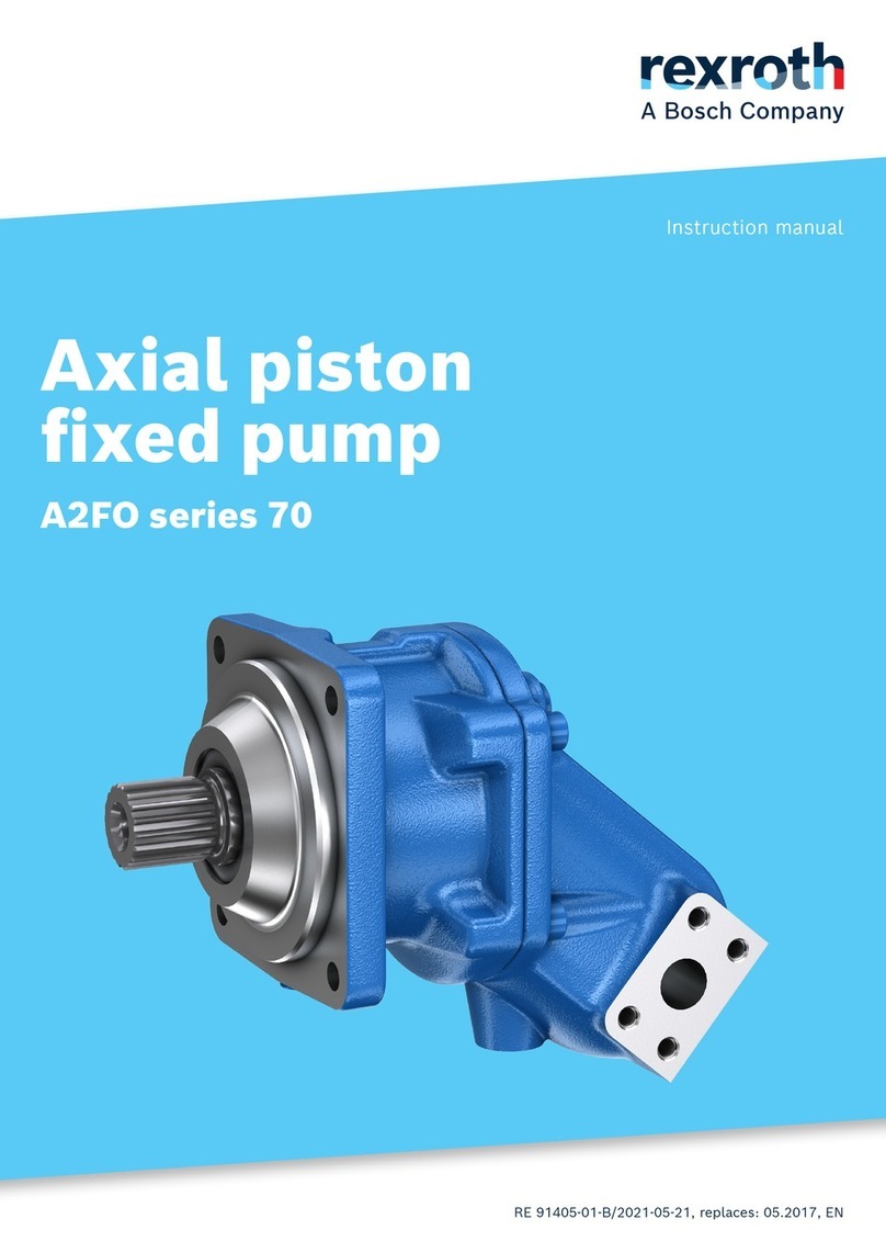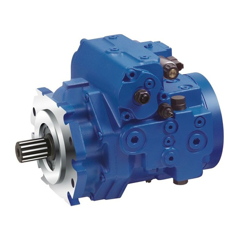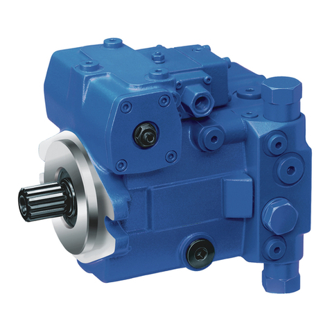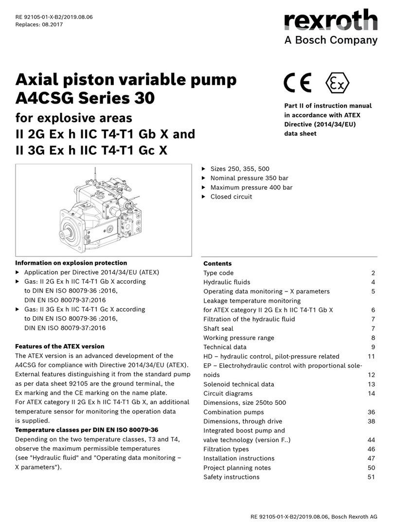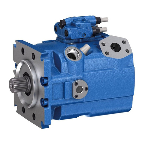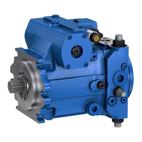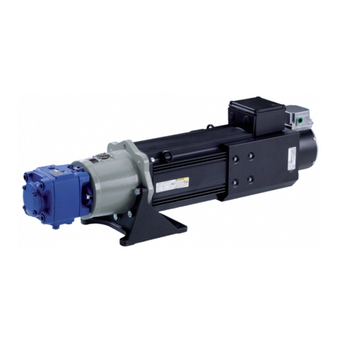
VPV Vane Pump 1
Table of Contents
Introduction 2
Benefits 2
Specifications 3
Ordering Guide 6
Performance Characteristics 9
Performance Characteristics - VPV 16 to 3000 PSI (210 Bar) 10
Performance Characteristics - VPV 25 to 3000 PSI (210 Bar) 12
Performance Characteristics - VPV 32 to 3000 PSI (210 Bar) 14
Performance Characteristics - VPV 45 to 3000 PSI (210 Bar) 16
Performance Characteristics - VPV 63 to 3000 PSI (210 Bar) 18
Performance Characteristics - VPV 80 to 3000 PSI (210 Bar) 20
Performance Characteristics - VPV 100 to 3000 PSI (210 Bar) 22
Performance Characteristics - VPV 130 to 3000 PSI (210 Bar) 24
Performance Characteristics - VPV 164 to 3000 PSI (210 Bar) 26
VPV 16, Single pump, S.A.E. ‘A’ flange, RH rotation, Installation Drawing 28
VPV 16, Single pump, Metric flange, RH rotation, Installation Drawing 29
VPV 25/32, Single pump, S.A.E. ‘B’ flange, RH rotation, Installation Drawing 30
VPV 25/32, Single pump, Metric flange, RH rotation, Installation Drawing 31
VPV 25/32, Single pump, S.A.E. ‘B’ flange, RH rotation, Installation Drawing 32
VPV 25/32, Single pump, S.A.E. ‘B’ flange, w/ solenoid 2-pressure compensator, Inst. Drw. 33
VPV 25/32, Single pump, S.A.E. ‘B’ flange, w/ NG6 pilot valve, Installation Drawing 34
VPV 45/63/80, Single pump, S.A.E. ‘C’ flange, RH rotation, Installation Drawing 35
VPV 45/63/80, Single pump, Metric flange, RH rotation, Installation Drawing 37
VPV 100/130/164, Single pump, S.A.E. ‘D’ flange, RH rotation, Installation Drawing 39
VPV 100/130/164, Single pump, Metric flange, RH rotation, Installation Drawing 41
VPV 16, Combination pump, S.A.E. ‘A’ flange, RH rotation, Installation Drawing 43
VPV 25/32, Combination pump, S.A.E. ‘B’ flange, RH rotation, Installation Drawing 44
VPV 32/16, Combination pump, S.A.E. ‘B’ flange, RH rotation, Installation Drawing 45
VPV 32/25, Combination pump, S.A.E. ‘F’ Gear pump, RH rotation, Installation Drawing 46
VPV 45/63/80 to VPV 16, S.A.E. & Metric Combination, Installation Drawing 47
VPV 45/63/80 to VPV 25/32, S.A.E. & Metric Combination, Installation Drawing 50
VPV 45/63/80 to an ‘F’ Gear pump, S.A.E. & Metric Combination, Installation Drawing 53
VPV 45/63/80 to an ‘G’ Gear pump, S.A.E. & Metric Combination, Installation Drawing 56
VPV 45/63/80 to VPV 45/63/80, S.A.E. & Metric Combination, Installation Drawing 58
VPV 100/130/164 to VPV 100/130/164 S.A.E. & Metric Combination, Installation Drawing 62
VPV 100/130/164 to VPV 16 S.A.E. & Metric Combination, Installation Drawing 64
VPV 100/130/164 to VPV 25/32 S.A.E. & Metric Combination, Installation Drawing 67
VPV 100/130/164 to VPV 45/63/80 S.A.E. & Metric Combination, Installation Drawing 70
VPV 100/130/164 to ‘F’ Gear pump, S.A.E. & Metric Combination, Installation Drawing 73
VPV Controls 77
Comparison of Sound Levels 79
Trouble Shooting 80
Adapter Kits for VPV Combinations Using P1 Pumps 81
Through Drive Horsepower Limitations 82
VPV Stroke Limiter Adjustment 83
2000 PSI Repair Parts 84
3000 PSI Repair Parts 90
Vane Tip Orientation 95
VPV Tool Kit 96
Reaction Characteristics and Shock Clipper Function 97

