manuals.online logo
Brands
  1. Home
  2. •
  3. Brands
  4. •
  5. BOSSCO
  6. •
  7. Music Pedal
  8. •
  9. BOSSCO Chorus CE-3 User manual

BOSSCO Chorus CE-3 User manual

PRECAUTIONS
•
When
the
CE-3
is
not
in
use
for
a
long
period,
remove
the
battery
to
prevent
the
trouble
caused
l)v
the
battery
look
age.
•
If
the
battery
voltage
drops,
effect
be¬
comes
inferior
or
no
sound
is
prod¬
uced.
To
prevent
that,
replace
the
bat¬
tery.
•
Be
sure
to
keep
the
battery
securely
connected
even
while
using
the
AC
Adaptor,
then
the
CE-3
will
continuerl
to
operate
even
if
the
AC
Adaptor
cord
comes
out
during
performance.
•
Unplug
the
cord
from
the
INPUT
jack
when
the
CE-3
is
not
in
use
to
avoid
wasting
the
battery.
Power
.
B
a
t
t
e
r
v
9V
(
1),
AC
Adaptor
(BOSS
ACA
series)
Power
Consumption
.
1
3
m
A
at
9V
Controls
.
R
A
FE
knob.
DEPTH
knob.
STEREO
MODE
switch
Others
.NORMAL/EF
FECT
selector
switch
(PEDAL
SWITCH),
Indicator
Jacks
.
I
N
P
U
T
jack.
OUTPUT
jacks
A
&
B,
AC
Adaptor
S/N
Ratio
.
o
vf;r
90
dB
(IMF
A)
Maximum
Output
Level
....
0
dB
rn
(
t
o
o
H?).
)0
dBm
(
i
kH?)
Input
Impedance
.
iMjz
(FET
input)
Output
Load
Impedance
.
.
.
over
lOku
Dimensions
.
70(W)
x
55(H)
x
125(D)
mm/
2-3/4(W)
X
2
1/4(H)
X
5''(D)
inches
Weight.
400q/i4
m
*
Specifications
are
subject
to
change
without
notice.
Products
of
Roland
Printed
in
Japan
Jul.
'87
E-3
C€-3
Chorus
INSTRUCTIONS
Adopting
the
stereo-out
system,
the
BOSS
effect
unit
CE-3
is
able
to
produce
exter-
mely
rich
chorus
sounds.
By
controlling
the
RATE
and
the
DEPTH
knobs
and
the
STEREO
MODE
switch,
you
can
obtain
wide
variations
of
the
chorus
sounds.
Moreover,
the
CE-3
is
designed
to
be
noise
free,
i.e.
the
S/N
ratio
is
more
than
90
dB
(IHF-A).
Also,
you
can
easily
see
wheather
the
effect
is
on
or
off
by
the
indicator
which
lights
up
when
the
CE-3
is
in
effect
mode.
•
Please
read
the
instructions
carefully
.
CAUTIONS
FOR
REPLACING
AND
HANDLING
BATTERY
REPLACING
BATTERY
USE
9-VOLT
BATTERY.
O
Loosen
the
screw
of
pedal
to
open
It
and
pull
battery
out.
©Replace
the
battery
with
a
fresh
one
and
put
it
into
position.
©Set
coil
spring
onto
the
projection
on
the
rear
of
the
pedal
and
shut
the
cover
(pedal).
Finally
insert
the
screw
into
the
pedal
guide
and
tighten
it.
At
this
time,
be
careful
not
to
catch
the
battery
strap
in
the
cover
or
coil
spring.
Doschelnigung
tlos
MorstnIInrt
/Itnporlfliits
Hicftnit
wird
liescheiiiigt.
(l.iR
dci/die/(Jas
CHOnuS
CE
3
in
Ut)ereinstimmut>g
rnil
den
Bestimnuingen
der
ArntsbI.
VIg
1046
/
1984
(link
entsiciit
lit.
Der
Deutsclien
Bundesposl
wwrde
das
Invcrkelirbringen
dieses
Cerates
ange/eigt
und
die
Deiechligung
zin
Uheiptidung
dei
Setir*
md
Einlialiiinq
del
Beslimmiingen
eingeraumt
Boland
Cotpornlion
Osaka
!
Japan
I
RADIO
AND
TELEVISION
INTERFERENCE
"Warning
This
oquirJ'r^oni
Ims
t>oori
vor
if
incf
to
coniplv
with
thn
limits
for
a
Class
B
corTipiiting
davico.
pursuant
to
Suhport
J,
of
Tort
15
of
rcC
ruins
Opnration
with
non
cor
11
f
ierl
or
non
verified
equip
rnent
is
likely
to
result
in
interference
to
radio
and
TV
reception,’
The
equipment
described
in
this
r^ionual
generates
and
uses
radio-frequency
energy
If
it
is
not
installed
and
used
properly,
that
is,
in
strict
accordance
with
our
instructions,
it
may
cause
interior
ence
with
radio
and
television
reception
This
equipment
has
been
tested
and
found
to
comply
with
the
limits
for
a
Class
B
cortiputing
device
in
nccordnnro
with
the
i|)Pr
1
f
u-n
t
m
ns
in
Sulitjnrt
J.
of
f’nr
t
If),
of
T
CC
ftules
I
hese
rules
are
designed
to
provide
reasonable
protection
against
such
a
interference
in
a
residential
installation.
However,
there
is
no
guarantee
that
the
interference
will
not
occur
in
a
particular
installation.
If
this
equipment
does
cause
interference
to
radio
or
television
reception,
whicfi
can
l>o
doterrTiinorf
by
turning
the
equipment
on
and
off.
the
user
is
encouraged
to
try
to
correct
the
interference
by
the
following
measure:
•
Disconrtnct
other
rlnvices
and
their
inpu
t
rou
tfru
t
rabies
one
at
a
tune
If
the
inter
fererico
stops,
it
IS
caused
by
either
the
other
device
or
its
I/O
cable.
These
devices
usually
require
Roland
designated
shielded
I/O
cables.
For
Roland
devices,
you
can
obtain
the
proper
shielded
cable
from
your
dealer
For
non
Roland
rievices,
contact
the
ntamifnclurer
or
dealer
for
assistance.
If
your
equipment
does
cause
interference
to
radio
or
television
reception,
you
can
try
to
correct
the
interference
by
using
one
or
more
of
the
following
measures:
•
Turn
the
TV
or
radio
antenna
until
the
interference
stops.
•
Move
the
equipment
to
one
side
or
the
other
of
the
TV
or
radio
•
Move
the
equipment
farther
away
from
the
T
V
or
radio.
•
Plug
the
equipment
into
an
outlet
that
is
on
a
different
circuit
than
the
TV
or
radio.
(That
is.
make
certain
the
equipment
and
the
radio
or
television
set
are
on
circuits
controlled
by
different
circuit
breakers
or
fuses.)
•
Consider
installirig
a
rooftop
television
antenna
with
coaxial
catrle
lead
in
tretween
the
antenna
arid
TV.
If
necessary,
you
should
consult
your
dealer
or
an
experiericed
radio/television
technician
for
additional
suggestions.
You
may
find
helpful
the
followirtg
booklet
prepared
by
the
Federal
Com¬
munications
Commission:
"How
to
Identify
and
Resolve
Radio
TV
In'erference
Problems"
This
booklet
is
available
from
the
US
Government
Printing
Office,
Washington.
DC.
20402,
Stock
No.
004
000
00345
4
OUTPUT
jacks
A
&
B
These
ore
output
jocks
to
connect
the
niTipli-
fior
to.
AC
Adaptor
jack
This
is
to
connect
the
AC
Adaptor
(BOSS
ACA
series)
to.
Pedal
Switch
This
Pedal
Switch
is
used
to
turn
the
effect
on
or
off.
•
Adopting
the
FET
switching
system,
this
Pedal
Switch
is
released
from
the
click
noise,
which
makes
even
more
successful
studio
recording
possible.
Indicator
If
you
press
the
Pedal,
this
Indicator
lights
up,
displaying
that
the
effect
is
on.
It
goes
out
in
pressing
it
again
showing
that
the
effect
is
off.
•
If
the
indicator
fails
to
light
or
become
dim¬
mer,
replace
the
battery
with
a
new
one.
Thumb
Screw
Loosen
this
screw
when
replacing
the
battery.
•
Do
not
remove
the
screw
from
the
Pedal.
OPERATION
Set
the
knobs
as
shown
left.
2
Press
the
Pedal
Switch
down,
and
the
Indicator
lights
up
displaying
that
the
effect
is
on.
It
goes
out
in
pressing
it
again
showing
that
the
effect
is
off.
If
the
Indicator
fails
to
light
up
or
becomes
dimmer,
replace
the
battery
with
a
new
one.
3
Adjust
the
rate
of
the
effect
by
using
the
RATE
knob.
4
Adjust
the
depth
of
the
effect
by
using
the
DEPTH
knob.
*
As
you
turn
the
RATE
knob
clock¬
wise,
the
depth
of
the
effect
will
grow
deeper.
5
Select
the
mode
you
like
with
the
STEREO
MODE
switch.
RATE
knob
This
ktiob
Is
to
control
the
rate
of
the
chorus
NAME
8c
FUNCTIONS
effect.
As
you
turn
it
clockwise,
the
rate
of
the
effect
will
be
quickntied.
AC
ADAPTOR
JACK
INDICATOR
DEPTH
^
STEREO
MODE
RATE
•-
OUTPUT
JACK
(B)
OUTPUT
JACK
(A)
-•
INPUT
JACK
PEDAL
SWITCH
.
THUMBSCREW
DEPTH
knob
This
knob
controls
the
depth
of
the
effect.
As
you
turn
it
clockwise,
the
depth
of
the
ef¬
fect
will
become
deeper.
STEftEO
MODE
switch
MODE
I.The
chorus
effect
is
obtain¬
ed
from
the
both
A
and
B
output
jacks.
"
If
using
only
orte
amplifier,
set
this
switch
to
MODE
I
(MONO),
and
connect
it
to
either
A
or
B
OU
IPUT
jack.
MODE
II
.
.
1
ho
soutrd
whoso
pitch
changes
alternately
will
bo
obtained
from
the
OUT¬
PUT
jack
A,
while
a
normal
sound
is
heard
from
the
OUTPUT
jack
B.
*
Connect
the
amplifiers
to
the
OUTPUT
jacks
A
and
B,
and
the
chorus
effect
is
ob¬
tained,
•
If
you
use
only
one
amplifier,
do
not
set
tfie
STEREO
MODE
switch
to
the
MODE
II
posi¬
tion.
Otherwise
the
chorus
effect
is
not
obtained.
INPUT
jack
This
is
the
input
jack
used
to
connect
the
mu¬
sical
instrument
such
as
a
guitar
to.
Important
Notes
•
Use
only
Hie
BOSS
AC
Adnplor
ACA
120,
220
or
2^0
(lepeiuliiM)
on
the
vollmie
sys
tf?tn
in
your
country.
,
,,
,
.
.
,
•
Do
not
use
the
CE-3
in
the
place
of
extreme
heat
or
huittidity,
or
where
it
may
be
ai
fected
by
dust.
,
,
v
oc
»
-tn
•
JUe
battery
(one
Dry
Battery,
9V)
will
last
for
20
to
50
hours
(manganese)
or
35
to
70
hours
(alkaline),
depending
on
the
conditions.
The
use
of
a
BOSS
ACA-Adaptor
and
alkaline
battery
is
recommended
for
a
longer
time
performance.
CONNECTIONS
AMPLIFIER
^
To
AC
Adaptor
jack
l^ovTnirQ
.,
iNfvr^-
GhorUs
.•C6-3
BOSS
CE-3
BOSS
AC
ADAPTOR
KEY
BOARD
WItnn
ihR
ornplillorj
otn
cotmnctocl
to
tho
OUT
TUI
locks
A
and
B,
the
chorus
sound
obtained
in
Mode
I
is
didetent
from
that
in
Mode
II.
Select
the
chorus
sound
you
like
by
citnnninq
lire
ntotlo.
Tho
cltnrus
sound
also
varies
dnnond
ing
on
tho
distance
ttciween
the
speakers.
Place
the
sitenk
s
where
you
can
obtain
the
(ovourite
chorus
sound.
irom
mat
in
iviooe
ii.
omcvi
me
jww..w
r
_
__—--
(^Rentember
to
disconnect
tlie
plug
from
tlie
INPUj
jack
whenjlte
CE-3
is
to
be
used
J

Other BOSSCO Music Pedal manuals

BOSSCO GL-100 User manual

BOSSCO

BOSSCO GL-100 User manual

BOSSCO BCB-60 User manual

BOSSCO

BOSSCO BCB-60 User manual

BOSSCO tremolo tr-2 User manual

BOSSCO

BOSSCO tremolo tr-2 User manual

BOSSCO BF-3 User manual

BOSSCO

BOSSCO BF-3 User manual
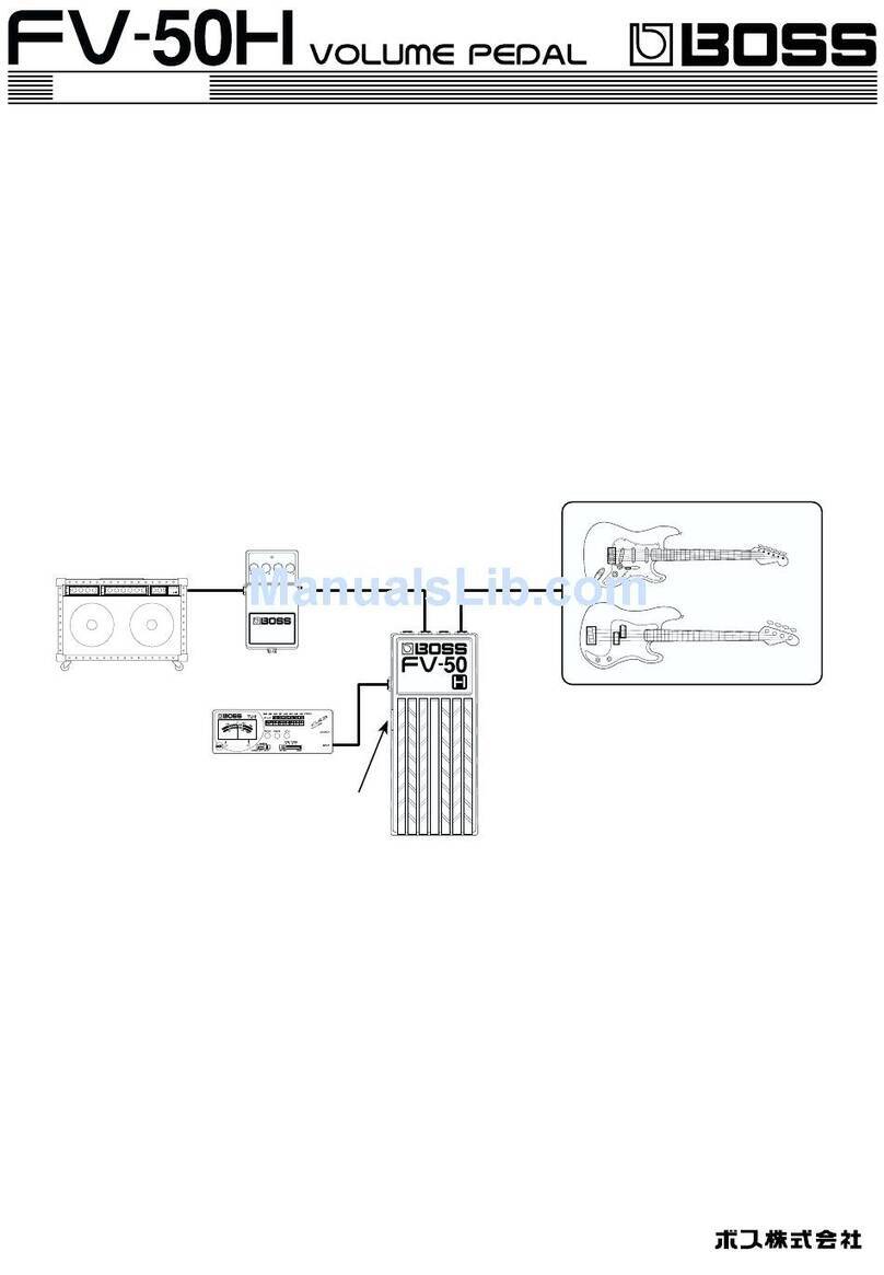
BOSSCO FV-50L User manual

BOSSCO

BOSSCO FV-50L User manual
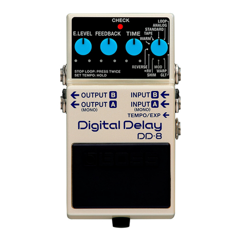
BOSSCO DD-8 User manual

BOSSCO

BOSSCO DD-8 User manual
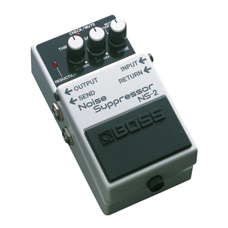
BOSSCO NS-2 Noise Suppressor User manual

BOSSCO

BOSSCO NS-2 Noise Suppressor User manual

BOSSCO ME-20 User manual

BOSSCO

BOSSCO ME-20 User manual

BOSSCO CE-2B Bass Chorus User manual

BOSSCO

BOSSCO CE-2B Bass Chorus User manual
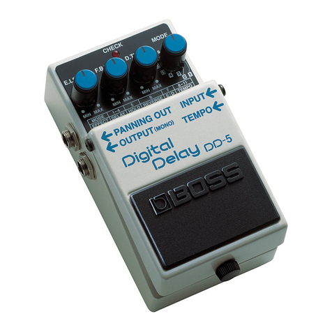
BOSSCO DD-5 Digital Delay User manual

BOSSCO

BOSSCO DD-5 Digital Delay User manual
BOSSCO TE-2 User manual

BOSSCO

BOSSCO TE-2 User manual

BOSSCO Drive Zone OD-20 User manual

BOSSCO

BOSSCO Drive Zone OD-20 User manual
BOSSCO DS-1 User manual

BOSSCO

BOSSCO DS-1 User manual

BOSSCO gt-8 Operating and maintenance manual
BOSSCO

BOSSCO gt-8 Operating and maintenance manual

BOSSCO BCB-60 User manual

BOSSCO

BOSSCO BCB-60 User manual
BOSSCO HF-2 User manual

BOSSCO

BOSSCO HF-2 User manual
BOSSCO RV-2 User manual

BOSSCO

BOSSCO RV-2 User manual
BOSSCO PW-2 Power Driver User manual

BOSSCO

BOSSCO PW-2 Power Driver User manual
BOSSCO AW-2 User manual

BOSSCO

BOSSCO AW-2 User manual

BOSSCO F1 Phaser User manual

BOSSCO

BOSSCO F1 Phaser User manual

BOSSCO BE-5B User manual

BOSSCO

BOSSCO BE-5B User manual

BOSSCO ME 6 User manual

BOSSCO

BOSSCO ME 6 User manual

BOSSCO ME-20 User manual

BOSSCO

BOSSCO ME-20 User manual

BOSSCO gt-8 User manual

BOSSCO

BOSSCO gt-8 User manual

Popular Music Pedal manuals by other brands

thomann Harley Benton MP-500 user manual

thomann

thomann Harley Benton MP-500 user manual

Red Panda BITMAP user manual

Red Panda

Red Panda BITMAP user manual

Rolls 962 owner's manual

Rolls

Rolls 962 owner's manual

Mooer Phaser Player owner's manual

Mooer

Mooer Phaser Player owner's manual

Mooer Micro Series owner's manual

Mooer

Mooer Micro Series owner's manual

Gig-fx VOD quick start guide

Gig-fx

Gig-fx VOD quick start guide

Origin Effects REVIVALDRIVE HOT ROD EDITION owner's manual

Origin Effects

Origin Effects REVIVALDRIVE HOT ROD EDITION owner's manual

GOD CITY INSTRUMENTS Decker Build guide

GOD CITY INSTRUMENTS

GOD CITY INSTRUMENTS Decker Build guide

Fender TRAPPER BASS DISTORTION manual

Fender

Fender TRAPPER BASS DISTORTION manual

MORLEY SLDW2 manual

MORLEY

MORLEY SLDW2 manual

Hughes & Kettner tubeman manual

Hughes & Kettner

Hughes & Kettner tubeman manual

Mooer Micro Series owner's manual

Mooer

Mooer Micro Series owner's manual

Dunlop MXR Sub Machine CSP210 manual

Dunlop

Dunlop MXR Sub Machine CSP210 manual

MORLEY SLST2 manual

MORLEY

MORLEY SLST2 manual

Behringer SUPER PHASE SHIFTER SP400 manual

Behringer

Behringer SUPER PHASE SHIFTER SP400 manual

Behringer Digital Multi-FX FX600 manual

Behringer

Behringer Digital Multi-FX FX600 manual

Philips ACC2310 user manual

Philips

Philips ACC2310 user manual

Dimavery EPPA-50 Preamp user manual

Dimavery

Dimavery EPPA-50 Preamp user manual

manuals.online logo
manuals.online logoBrands
  • About & Mission
  • Contact us
  • Privacy Policy
  • Terms and Conditions

Copyright 2025 Manuals.Online. All Rights Reserved.