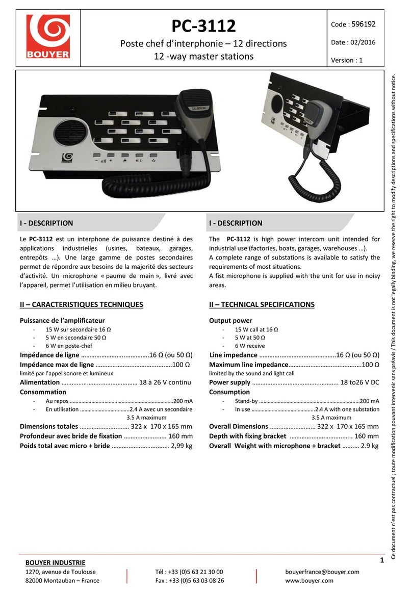
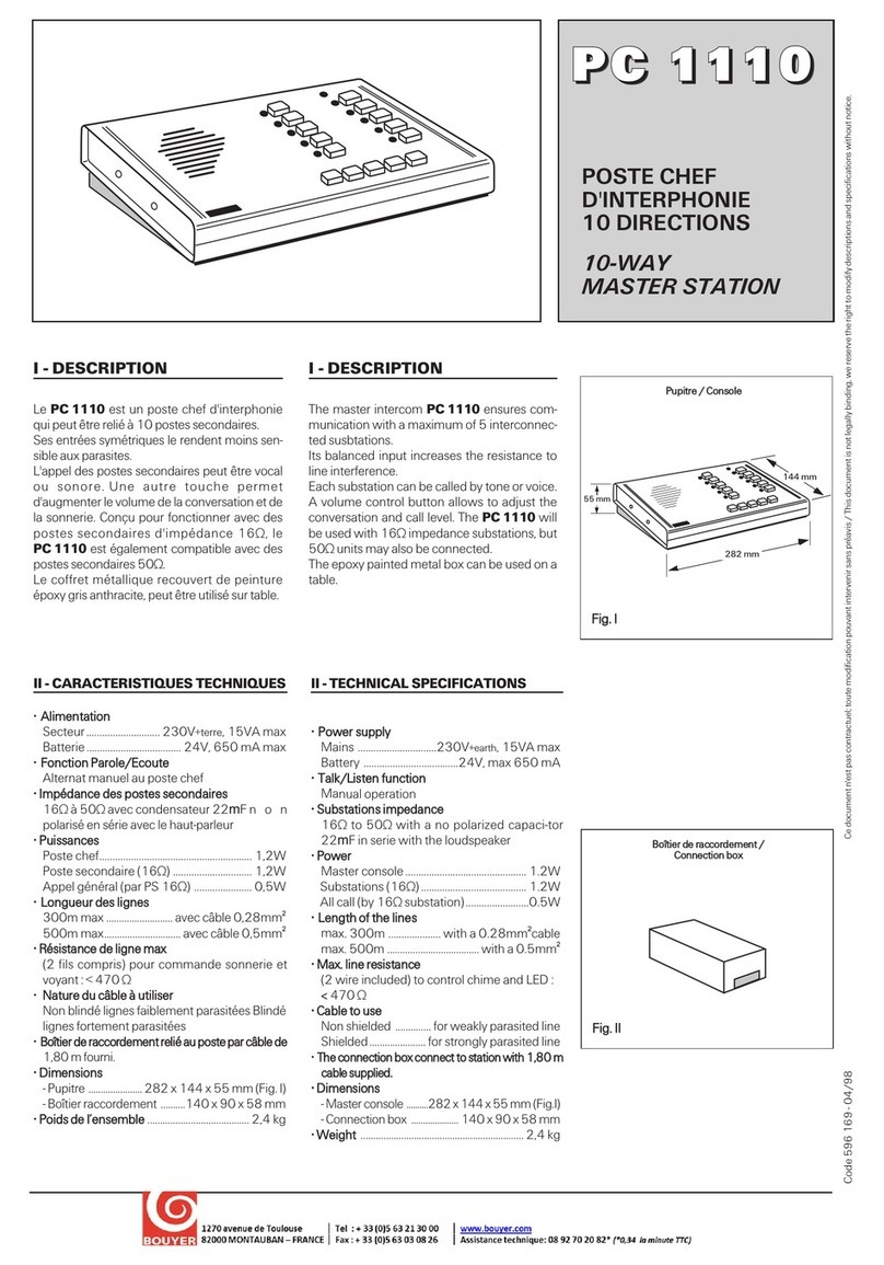
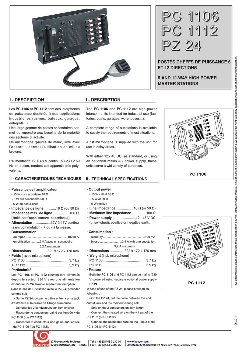
Bouyer PC-2112 User manual

PC-2112 / PC-2108 / PC-2104
Postes chefs d’interphonie : 12 / 8 / 4 directions
12 / 8 / 4 ways master stations
Code : 596191
Date : 02/2016
Version : 1
1
BOUYER INDUSTRIE
82000 Montauban –France Fax : +33 (0)5 63 03 08 26 www.bouyer.com
I - DESCRIPTION
I - DESCRIPTION
Les PC-2112, PC-2108, PC-2104 sont des postes-chefs
d’interphonie qui peuvent être reliés respectivement à 12, 8
et 4 postes secondaires.
L’appel des postes secondaires peut-être vocal ou sonore.
Une combinaison de touches permet d’augmenter le volume
de la conversation. Conçu pour fonctionner avec des postes
secondaires d’impédance 16Ω, ils sont également
compatibles avec des postes secondaires 50Ω.
Le coffret métallique recouvert de peinture époxy peut être
utilisé sur table (coller les pieds livrés dans l’emballage) ou
fixé verticalement sur un mur.
Masters intercom PC-2112, PC-2108, PC-2104 ensures
communication with respectively 12, 8, 4 interconnected
subsations.
Each substation can be called by tone or voice.
A volume control button combination allows to adjust the
conversation. They will be used with 16Ω impedance
substations, but 50Ω units may also be connected.
The epoxy painted metal box can be used on a table (Glue
the feet delivered in the package) or fixed on a wall.
II –CARACTERISTIQUES TECHNIQUES
II –TECHNICAL SPECIFICATIONS
Alimentation
Bloc secteur ………………………………………………….….24V, 2500 mA max
Fonction Parole / Ecoute
Alternat manuel au poste chef
Impédance des postes secondaires
16Ω à 50Ω avec condensateur 22mF non polarisé en série avec le
HP
Puissance
Poste chef ……………………………………………………………………………….1.2W
Poste secondaire (16Ω) …………………………………………………………..1.2W
Appel général (par PS 16Ω) …………………………………………………….0.5W
Longueur des lignes
300m max ……………………………………………avec câble blindé 0.28mm²
500m max ……………………………………………..avec câble blindé 0.5mm²
Résistance de ligne max
(2 fils compris) pour commande sonnerie et voyant < 470Ω
Nature du câble à utiliser
Paire Blindée
Boîtiers de raccordements relié au poste par câble 2m
Power supply
AC adapter……………………………………………….…….24V, 2500 mA max
Talk / Listen function
Manual operation
Substations impedance
16Ω to 50Ω with a no polarized capacitor 22mF in serie with the
loudspeaker
Power
Master console …………………………………………………………………..….1.2W
Substations (16Ω) ………………………………………………………………….1.2W
All call (by 16Ω substation) ……………………………………………..…….0.5W
Lenght of the lines
Max 300m ..……………………………………with a 0.28mm² shielded cable
Max 500m ………………………………………with a 0.5mm² shielded cable
Max line resistance
(2 wire icluded) to control chime and LED : < 470Ω
Cable to use
Shielded pair
Connection boxes connected to master with a 2m cable
Ce document n’est pas contractuel ; toute modification pouvant intervenir sans préavis / This document is not legally binding, we reserve the right to modify descriptions and specifications without notice.

PC-2112 / PC-2108 / PC-2104
Postes chefs d’interphonie : 12 / 8 / 4 directions
12 / 8 / 4 ways master stations
Code : 596191
Date : 02/2016
Version : 1
2
BOUYER INDUSTRIE
82000 Montauban –France Fax : +33 (0)5 63 03 08 26 www.bouyer.com
III - PRESENTATION
III - PRESENTATION
PUPITRE (Fig. I à IX)
① Voyant d’alimentation
②Voyants d’appel et de prise en ligne
③ Emplacement étiquettes d’identification ligne
④Boutons de prise de ligne
⑤Contrôle Volume -
⑥Contrôle Volume +
⑦Touche Sonnerie
⑧Touche Parole / Ecoute
⑨Touche Appel Général
⑩Touche Commande gâche
⑪Haut-parleur
⑫Jack alimentation 24V
⑬Ligne PS 1 à 4
⑭Ligne PS 5 à 8 (PC2108, PC2112)
⑮Ligne PS 9 à 12 (PC2112)
⑯Contact sec gâche électrique
CONSOLE (Fig. I to IX)
① Power supply indicator
②Call and line indicators
③ Place of identification line sticker
④ Line push-buttons
⑤Volume control -
⑥Volume control +
⑦Chime push-button
⑧Talk / Listen push-button
⑨All call push-button
⑩Control door release push-button
⑪Loudspeaker
⑫ Power supply 24V Jack
⑬ Substation 1 to 4
⑭ Substation 5 to 8 (PC2108, PC2112)
⑮ Substation 9 to 12 (PC2112)
⑯Control door switch
Dimensions
Pupitre ……………………………………………………………….260 x 160 x 51 mm
Boîtier raccordement ……………………………………………74 x 50 x 27mm
Poids …………………………………….……………………..……… 1.55 Kg
Dimensions
Master console …………………………………………..…….260 x 160 x 51 mm
Connection box ………………………………….……………..…74 x 50 x 27mm
Weight …………………………………….………………....……… 1.55 Kg
.
PUPITRE / CONSOLE
BOITIER DE RACCORDEMENT / CONNECTION BOX
240 mm
145 mm
50 mm

PC-2112 / PC-2108 / PC-2104
Postes chefs d’interphonie : 12 / 8 / 4 directions
12 / 8 / 4 ways master stations
Code : 596191
Date : 02/2016
Version : 1
3
BOUYER INDUSTRIE
82000 Montauban –France Fax : +33 (0)5 63 03 08 26 www.bouyer.com
Fig. I
1
2
3
4
5
6
7
8
9
10
11
12
Fig. III
12
13
14
15
16
Fig. II

PC-2112 / PC-2108 / PC-2104
Postes chefs d’interphonie : 12 / 8 / 4 directions
12 / 8 / 4 ways master stations
Code : 596191
Date : 02/2016
Version : 1
4
BOUYER INDUSTRIE
82000 Montauban –France Fax : +33 (0)5 63 03 08 26 www.bouyer.com
12
13
14
16
1
2
3
4
5
6
7
8
Fig. VI
Fig. V
Fig. IV

PC-2112 / PC-2108 / PC-2104
Postes chefs d’interphonie : 12 / 8 / 4 directions
12 / 8 / 4 ways master stations
Code : 596191
Date : 02/2016
Version : 1
5
BOUYER INDUSTRIE
82000 Montauban –France Fax : +33 (0)5 63 03 08 26 www.bouyer.com
1
2
3
4
Fig. IX
Fig. VIII
12
13
16
Fig. VII

PC-2112 / PC-2108 / PC-2104
Postes chefs d’interphonie : 12 / 8 / 4 directions
12 / 8 / 4 ways master stations
Code : 596191
Date : 02/2016
Version : 1
6
BOUYER INDUSTRIE
82000 Montauban –France Fax : +33 (0)5 63 03 08 26 www.bouyer.com
BOITIER DE RACCORDEMENT (Fig. X)
Pour établir les connexions avec les postes secondaires,
des boitiers de raccordement sont nécessaires (fig. X).
Connecter chaque cordon RJ45 ① aux prises ⑬, ⑭
(PC-2112 et PC-2108) et ⑮(PC-2112) du pupitre.
Connecter les câbles de lignes au bornier ②
conformément à l’ordre indiqué fig. X, et relier chaque
blindage aux borniers ③.
①Cordon de liaison RJ45 blindé vers pupitre
②Bornier de branchement des lignes secondaires
③Plot de branchement des blindages de lignes PS
④Fixation des cordons PS
CONNECTION BOX (Fig. X)
To establish connections with substations, it is necessary
to use three connexion boxes (fig. IV). Connect every RJ45
cable ① to the console connectors ⑬, ⑭(PC-2112 and
PC-2108) and ⑮(PC2112). Connect substations cables
to the terminal block ② according to the order specified
fig. X, and connect every shield to terminal block ③.
①RJ45 shielded connection cable to console
②Connection line terminals
③Shielded line terminals
④substation cable fixing
1
2
3
4
Fig. X

PC-2112 / PC-2108 / PC-2104
Postes chefs d’interphonie : 12 / 8 / 4 directions
12 / 8 / 4 ways master stations
Code : 596191
Date : 02/2016
Version : 1
7
BOUYER INDUSTRIE
82000 Montauban –France Fax : +33 (0)5 63 03 08 26 www.bouyer.com
IV - INSTALLATION
IV - INSTALLATION
ATTENTION
L’appareil ne doit pas être exposé aux chutes
d’eau et aux éclaboussures.
Avant toute intervention dans l’appareil, déconnecter le
câble d’alimentation.
Le pupitre peut être utilisé sur une table (coller les pieds
livrés dans l’emballage) ou fixé verticalement au moyen
des trous situés à l’arrière du coffret (décoller les pieds).
Les boîtiers de raccordement seront fixés à proximité
compte tenu de la longueur des cordons de liaison (2m)
et de l’arrivée des lignes des postes secondaires. Utiliser
les 2 trous de fixation ④(Fig. X).
ATTENTION
Les boîtiers de raccordement ne doivent pas être installés
en position verticale avec l’ouverture d’entrées
lignes vers le haut.
Raccorder le poste secondaire au bornier avec
du câble 2 conducteurs blindé. Relier les blindages au
bornier ③(Fig. IV).
Attacher les fils aux trous à l’aide de colliers anti
bloquants.
Replacer le capot de protection.
Le PC-2112 est alimenté par bloc adaptateur secteur/24V,
relié à la prise jack d’alimentation ⑫(Fig. II).
ATTENTION
The unit is neither water –nor splash proof.
Before any manipulation, disconnect the mains
cable.
PC-2104 can be used on a table table (Glue the feet
delivered in the package) or fixed on the wall thaks to the
holes on the back of the box (unstick the rubber feet).
Connection box will be nearly setted because of the
lenght of the connection cables (2m), and of the arrival of
substations lines. Use the 2 holes of setting ④ (Fig. X).
ATTENTION
The connection boxes cannot been installed in vertical
position with the line input to the upper side.
Connect substations on with 2 conductors
shielded cable. Connect the shield to the terminal ③
(Fig. IV).
Bind cable to the holes with the autolockable rings.
Put the protection cover.
PC-is supplied by a 24V AC/DC adapter, connected to ⑫
jack power connector (Fig. II).

PC-2112 / PC-2108 / PC-2104
Postes chefs d’interphonie : 12 / 8 / 4 directions
12 / 8 / 4 ways master stations
Code : 596191
Date : 02/2016
Version : 1
8
BOUYER INDUSTRIE
82000 Montauban –France Fax : +33 (0)5 63 03 08 26 www.bouyer.com
V - UTILISATION
V –USE
En position d’attente, toutes les touches sont relevées et
les voyants bleus éteints. Le voyant vert est allumé.
POUR APPELER UN POSTE SECONDAIRE
Enfoncer la touche de ligne correspondante ④.
Le voyant ② s’allume.
Dans le cas d’un appel par sonnerie, appuyer
simultanément sur les touches ⑧et ⑦.
Ensuite appuyer sur la touche ⑧pour parler et la
relâcher pour écouter.
Dans le cas d’un appel vocal, appuyer sur la touche ⑧
pour parler et la relâcher pour écouter.
En fin de conversation, relâcher la touche ④.
Le voyant ② s’éteint.
APPEL GENERAL
Pour parler aux postes secondaires en même temps,
appuyer sur la touche ⑨.
Pour faire un appel sonnerie vers les postes secondaires,
appuyer simultanément les touches ⑨et ⑦.
Pour isoler d’un appel général un ou plusieurs postes
secondaires, appuyer la ou les touches correspondant à
ces postes (voyants allumés) avant d’appuyer sur la
touche ⑨. Après l’appel général, relâcher la ou les
touches secondaires (voyants éteints).
LORSQU’UN POSTE SECONDAIRE APPELLE
La sonnerie fonctionne durant la pression de la touche
d’appel au poste secondaire.
Le voyant correspondant ② s’allume et reste allumé
pour mémoriser l’appel.
Enfoncer la touche ligne correspondante ④.
Le voyant reste allumé.
Appuyer sur la touche ⑧pour parler et relâcher pour
écouter.
En fin de conversation, relâcher la touche ④.
Le voyant ② s’éteint.
COMMANDE GÂCHE
Appuyer sur la touche ⑩pour commander la gâche.
In stand by position, all the push-buttons are unlatched,
and the blue LED is switched. Green LED is on.
TO CALL A SUBSTATION
Press the line push-button ④.
LED ② switches ON.
To make a call by chime, push simultaneously push-
buttons ⑧and ⑦.
Then, press push-button ⑧to talk and unlatch to listen
To make a call by speech, press push-button ⑧ to talk
and unlatch to listen.
At the end of the conversation, unlatch the push-button
④. LED ② switches off.
ALL CALL
To be in communication with the substations at the same
time (all call mode) press button ⑨.
To make a call with chime to the substations, press
simultaneoulsy button ⑨and ⑦.
To exclude from an all call on or several sustations, press
the dedicated button (LEDS ON), before pressing button
⑨. When the call is finished, unlatch these buttons
(LEDS OFF).
WHEN A SUBSTATIONS IS CALLING
Chime works during pressing the call push-button of the
substation.
Corresponding LED ② switches on and stays on to
memorize the call.
Press the corresponding line push-button ④.
LED stays ON.
Press the push-button ⑧to talk and unlatch to listen.
At the end of the conversation, unlatch the push-button
④.
LED ② switches off.
DOOR LOCK CONTROL
Press the push-button ⑩to control the electric door
lock.

PC-2112 / PC-2108 / PC-2104
Postes chefs d’interphonie : 12 / 8 / 4 directions
12 / 8 / 4 ways master stations
Code : 596191
Date : 02/2016
Version : 1
9
BOUYER INDUSTRIE
82000 Montauban –France Fax : +33 (0)5 63 03 08 26 www.bouyer.com
VOLUMES
Les boutons ⑤et ⑥ (Fig. I, Fig. IV, Fig. VII) permettent
d’ajuster les volumes de la conversation et de la sonnerie.
Un appui sur la touche ⑥ augmente le volume d’écoute
d’un pas, un appui sur la touche ⑤ diminue le volume
d’écoute d’un pas. Il y a au total 64 pas de réglage.
Un appui sur la touche ⑥ tout en maintenant la touche
Parole/Ecoute ⑧augmente le volume de parole d’un
pas. Un appui sur la touche ⑤tout en maintenant la
touche Parole/Ecoute ⑧diminue le volume d’écoute
d’un pas.
Un appui sur la touche ⑥tout en maintenant appuyée la
touche Sonnerie ⑦augmente le volume de sonnerie
d’un pas, un appui sur la touche ⑤ tout en maintenant
appuyée la touche Sonnerie ⑦diminue le volume
d’écoute d’un pas (en cas d’appel d’un poste secondaire,
la sonnerie se coupe sur l’une de ces deux actions).
Un appui simultané sur les touches ⑤ et ⑥ augmente
le volume de 10 dB (Parole, Ecoute et Sonnerie).
VOLUMES
Push buttons ⑤and ⑥(Fig. I, Fig. IV, Fig. VII) allow the
volume control of the conversation and of the chime.
Pressing button ⑥increases Listen volume by one step.
Pressing button ⑤decreases Listen volume by one step.
The number of adjustments is 64 steps.
Pressing button ⑥ while keeping the Talk/Listen button
⑧ pressed increases Talk volume by one step. Pressing
button ⑤ while keeping the Talk/Listen button ⑧
pressed decreases Talk volume by one step.
Pressing button ⑥ while keeping the Chime button ⑦
pressed increases Chime volume by one step. Pressing
button ⑤ while keeping the the Chime button ⑦
pressed decreases Chime volume by one step (In case of
call of a substation, the bell cuts itself on one of these
two actions).
Pressing simultaneously buttons ⑤ and ⑥ increase by
10 dB the volume (Talking, listening and Chime)
VI -RECOMMANDATIONS
VI - RECOMMANDATIONS
RISQUE DE CHOCS ELECTRIQUES - NE PAS
OUVRIR
Pour éviter les risques de chocs électriques,
ne pas enlever le couvercle.
Aucun entretien de pièces intérieures par
l'usager, confier l'entretien au personnel qualifié.
Pour éviter les risques d'incendie ou
d'électrocution, n'exposez pas cet article à la
pluie ou à l'humidité.
En fin de vie du produit, s’il est installé sur le
territoire français (DOM-TOM inclus), veuillez
contacter BOUYER pour organiser sa destruction
conformément à la directive DEEE. Dans le cas
contraire, veuillez appliquer la règlementation
locale du pays d’installation du produit.
RISK OF ELECTRICAL SHOCK –DO NOT REMOVE
COVER
To reduce the risk of electrical shock, do not
remove cover. No user serviceable parts inside.
Refer servicing to qualified service personnel.
The unit is neither water –nor splash proof.
This product is subject to European regulation
2002/96/CE (also called W.E.E.E).
Please contact your local dealer for destruction in
end of life.
This manual suits for next models
2
Table of contents
Other Bouyer Control System manuals
Popular Control System manuals by other brands
ETC
ETC Rover user guide
Pure Processing
Pure Processing PureClear Instructions for use
Roger
Roger MCT80M operating manual
Carrier
Carrier PRO-DIALOG PLUS 50AZ Installation, operation and maintenance instructions
McCue
McCue BOL-WALKWAY installation instructions
Trane
Trane Tracer Concierge installation instructions
