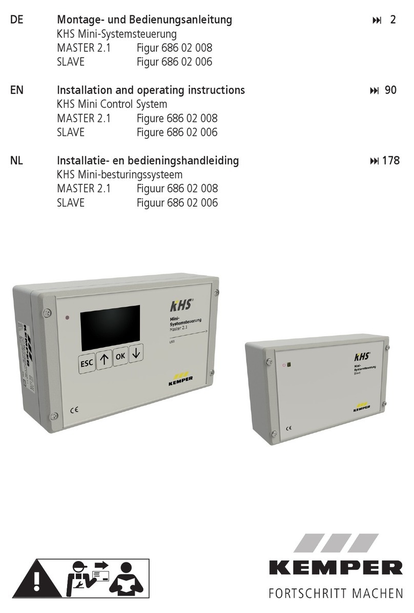
Kemper KHS Mini Control System MASTER 2.0 User manual

Installation and Operating instructions
KEMPER KHS Mini Control System
KHS Mini Control System MASTER 2.0 Figure 686 02 008
KHS Mini Control System SLAVE Figure 686 02 006

K410068602008-00 / 09.2018 2
TABLE OF CONTENTS
INFORMATION .......................................................................................3
1.1 Precautions ................................................................................................. 3
1.2 Important advice to the operator ................................................................... 3
1.3 Technical Data............................................................................................. 4
1.4 Scope of delivery | Accessories...................................................................... 5
INSTALLATION.......................................................................................6
2.1 Wall mounting ............................................................................................. 6
2.2 Electrical installation .................................................................................... 7
2.3 Bus system overview ..................................................................................11
COMMISSIONING .................................................................................14
3.1 Menu navigation .........................................................................................14
3.1.2.1 System settings ........................................................................................16
3.1.2.2 CAN bus setup ..........................................................................................18
3.1.2.3 Device settings..........................................................................................19
3.1.2.4 Operating modes .......................................................................................23
3.1.2.5 Logbook ...................................................................................................27
3.1.2.6 Change Program........................................................................................27
3.1.2.7 Valve manual mode ...................................................................................28
ACKNOWLEDGE ERROR.........................................................................30
USB INTERFACE....................................................................................30
WEB BROWSER.....................................................................................31
6.1 Basic menu operation and functions ..............................................................31
6.2 System settings..........................................................................................33
6.3 Device settings...........................................................................................35
6.4 Operating modes ........................................................................................50
6.5 Overview ...................................................................................................60
6.6 Current values............................................................................................61
6.7 Data transfer..............................................................................................62
6.8 E-Mail administration ..................................................................................67
ERROR DESCRIPTION AND ERROR HANDLING .....................................69
ACCESSORIES | SPARE PARTS..............................................................71
KHS CABLE LIST ...................................................................................73
APPENDIX ............................................................................................74
10.1 Valve technologies ......................................................................................74
10.2 Overview for system commissioning..............................................................76

K410068602008-00 / 09.2018 3
INFORMATION
For installation, maintenance and operation
Installation and operation
Read the manual and follow the instructions
before installation!
Installation and maintenance must be carried
out by qualified plumbers.
Provide the manual to the plant operator and
keep on hand for further reference!
Make sure that the installation location is
frost-proof and not prone to flooding.
Priority must be given to the national
standards and provisions on sanitary
installations and accident prevention.
Warranty
No warranty in case of:
- Non-compliance with the manual.
- Damage due to incorrect installation.
- Unauthorised modification of the product.
Use
Thanks to the MASTER/SLAVE technology,
KHS Mini Control System can be used to
implement specific water exchanging
measures to maintain drinking water
hygiene. For each individual water
exchange group, time or temperature-
controlled water exchange can be
configured individually or according to a
specified water volume.
Only skilled professional personnel are
permitted to operate electrical systems in
accordance with DIN EN 50110-1.
Do not use the device for other purposes
than described above in non-freezing
interiors. Any other uses constitute misuse.
Warnings used in the manual:
Warning!
Highlights risks that may result
in injury, material damage or
contamination of drinking
water.
Note!
Highlights risks that may result
in damage to the plant or
dysfunction.
▪The reliability of the supplied unit is
only ensured when used as intended.
Never exceed the limits stated in this
documentation under any circum-
stances
▪During assembly and maintenance,
make sure that the control is not
switched on.
▪Use only original/approved spare parts
otherwise no warranty claims will be
recognized.
▪Be sure to comply to local regulations
on waste recycling and disposal.

K410068602008-00 / 09.2018 4
Technical Data
Operating voltage
230V, AC, 50 / 60Hz
Power input for the unit
10 W
Relay flushing valve output
230 V, 2 A
Relay alarm output
max. 230 V, 2 A
CAN bus subscribers
max. 62
Logbook entries
max. 50,000
Datalogging entries
max. 12 million
Ambient temperature range
0 °C to + 50 °C
Degree of protection
IP 54
Dimensions
200 x 130 x 60 [mm]
Integrated user interface (display + 4 keys)
▪Settings
▪Configuration
▪System overview
▪Data transfer
Network interface for web-based user
interface
▪Settings
▪Configuration
▪System overview
▪Data transfer
▪E-mail management (fault message)
USB interface for USB mass storage
▪Firmware update
▪Web server update
▪Reading out the flushing log
▪Reading out the logbook
▪Reading the configuration in and out
Language menu
▪German
▪English
▪Dutch
Operating modes
Time controlled water exchange
Temperature controlled water exchange
Volume controlled water exchange
Routine
Datalogging
Backup
External switch function
▪Change program
▪System lock / Maintenance operation

K410068602008-00 / 09.2018 5
Art.-No.
H1
[mm]
L1
[mm]
T1
[mm]
6860200800
120
200
58
Fig.
686 04
686 05
688 00
628 0G
138 4G
685 15
689 06 001
689 06 002

K410068602008-00 / 09.2018 6
Installation
Allow only certified electricians to assemble and install electrical equipment.
Danger of fatal electric shock.
Rigid leads must form a loop for wiring so that there is no pressure on the
terminals and the housing closes without resistance.
Ill. 1 Illustration of the mounting holes for wall installation
Disturbance
space
Please pay attention to the disturbance space when installing the Control
System.
Left-hand side: Serial number of the KHS Mini Control System
Right-hand side: USB slot

K410068602008-00 / 09.2018 7

K410068602008-00 / 09.2018 8
2.2.1 Connection of the components
Terminal
characters
Meaning
1
Flushing valve –Switching output 230V
2
L (+)
Flushing valve –Voltage output 230V
3
N (-)
Flushing valve –N
4
L (+)
Power supply –L1 230V
5
N (-)
Power supply –N
6
SW IN
External input - 230V (MASTER only)
7
PE
Protective earth conductor –PE
8
H
A CAN bus –High
9
L
A CAN bus –Low
10
GND
A CAN bus –Ground
11
H
B CAN bus –High
12
L
B CAN bus –Low
13
GND
B CAN bus –Ground
14
+ 5V
Flow measurement valve –Voltage output 5V
15
FLOW
Flow measurement valve –Flow input
17
GND
Flow measurement valve –Ground
18
Input 1 Pt1000
19
Input 1 Pt1000
20
Input 2 Pt1000
21
Input 2 Pt1000
22
IN
Free drain / water sensor (conductors interchangeable)
23
IN
Free drain / water sensor (conductors interchangeable)
24
Alarm relay –External voltage input
25
Monitoring of ext. voltage = Fault
26
Monitoring of ext. voltage = Operation
24
25
26
1
2
3
4
5
6
7
8
9
10
11
12
13
14
15
17
18
19
8
20
21
22
23

K410068602008-00 / 09.2018 9
KHS isolating valve + spring reset (Fig. 686 05)
KHS isolating valve (Fig. 686 04)
KHS CONTROL-PLUS (Fig. 138 4G)
[4] →bn (BN) = L
[5] →bu (BU) = N
[7] →ye/gn (YE/GN) = PE
L N PE
230V 230V +/- 10% AC 50/60Hz
Back-up fuse max. 16A
[6] →bn (BN) = L
Switch
230V 230V +/- 10% AC 50/60Hz
Back-up fuse max. 16A
[1] →bn (BN)
[2]
[3] →bu (BU)
bn bu
[1] →bn (BN)
[2] →bl (BK)
[3] →bu (BU)
bn bl bu
[14] →bn (BN)
Pt 1000 (optional) [15] →bu (BU)
[17] →bl (BK)
[18]
bn bu bl gy wh [19] →gy (GY) = Pt 1000 (optional)
[20] →wh (WH) = Pt 1000 (optional)
[21]
If the temperature is measured
using the CONTROL-PLUS, the
jumper on the board must be
changed from 4-wire to 2-wire.

K410068602008-00 / 09.2018 10
KHS temperature measurement valve
(Fig. 628)
KHS Free Drain (Fig. 688 00)
Water sensor for leaks (Fig. 620 00)
Potential-free alarm relay
[22] →ws (WH)
[23] →br (BN)
ws br
In the as-delivered state, a
cable bridge is plugged
between Terminals 22 and
23. This must be removed
before connecting the KHS
Free Drain.
[22] →wh (WH)
[23] →bn (BN)
wh bn
In the as-delivered state, a cable
bridge is plugged between
Terminals 22 and 23. This must
be removed before connecting the
KHS water sensor.
[24] →230V (2A) / 24V
[25] →OUT (fault)
[26] →OUT (operation)
230V (2A)
24V
Monitoring example: Faults and
mains voltage failures are reported
with external voltage to the
network warning lamp, the
warning horn or to the BMS.
ws
rt
BMS
Warning lamp
Signal horn

K410068602008-00 / 09.2018 11
2.3.1 CAN bus cable
Bus cables for the wiring of CAN bus systems (controller area network) in accordance with
ISO 11898 must be used for bus systems with 120 Ω nominal impedance. Only when such
cables are used can a high level of data transfer security be guaranteed.
Recommended properties for the CAN bus cable
Cable type
CAN bus cable
Conductor material
Kupfer
Conductor cross-section and number of
wires
Cross-section Length
1 x 2 x 0,34 mm²
1 x 2 x 0,50 mm²
1 x 2 x 0,75 mm²
300 m
500 m
1000 m
Shielding
Braiding of tinned copper wires
Impedance at f ≥1Hz
120 Ω ±15 %
2.3.2 CAN-Bus-Anschluss
Components
Designation
Number
of subscribers
per component
Max. number of
components per
-MASTER-
Control System SLAVE
1
62
KHS HS2 Hygiene
flushing box with one
connection
+
Can bus connection set
1
60
KHS HS2 Hygiene
flushing box with two
connections
+
Can bus connection set
2
30
The KHS Mini Control System has two
integrated CAN bus connections with
which up to 62 CAN bus participants can
be addressed. A maximum of 31 bus
subscribers can be connected to each
CAN bus connection.
max. 31 CAN
bus subscribers
max. 1000 m
(in total)
max. 31 CAN bus
subscribers
max. 1000m (in
total)
CAN bus
Connection B
CAN bus
Connection A
2
1

K410068602008-00 / 09.2018 12
KHS HS2
KHS HS2
KHS HS2
2.3.3 CAN bus subscriber arrangement
2.3.4 CAN bus cable connection
Wrong topology! Only line
topology allowed!
RIGHT
RIGHT
WRONG
Device 1
Device 2
CAN bus cable 1
CAN bus cable 2

K410068602008-00 / 09.2018 13
2.3.5 Terminal resistor
The 120 Ω terminal resistor may only be installed in the last control component of a CAN bus
cable. The MASTER does not require a terminal resistor.
2.3.6 Connection of terminal resistor
All KHS Mini Controls
-SLAVE- are supplied with a
120 Ω terminal resistor.
For non-terminal SLAVE
controls, the resistor must
be removed!
A
l
l
e
K
H
S
M
i
n
i
S
t
e
u
e
r
u
n
g
e
n
-
S
L
A
V
E
-
w
e
r
d
e

K410068602008-00 / 09.2018 14
Commissioning
Before commissioning, make sure the
connections have been made properly and
professionally and that the system is
properly protected. The pertinent
regulations (EN, VDE, etc.) and the
regulations of the local energy utility must
be complied with. After finishing the wall
installation and the electrical installation,
apply the mains voltage of 230V.
Allow only certified electricians to assemble and install electrical equipment.
Danger of fatal electric shock.
To simplify configuration and to guarantee correct installation, fill in the
system commissioning overview of the KHS Mini Control System (see supply
pressure, Chapter 10.2) before making the settings.
It is mandatory to fill in the form to be able to take advantage of the
optional factory support.
All menus have a "rolling" structure, i.e.,
pressing the "↓key" on the last menu item
jumps back to the first menu item.
Keys
Description
Esc
Exit the menu / switch between overview and main menu
Roll backwards
OK
Confirm key
Roll forwards
The menu navigation of the KHS Mini Control System –MASTER 2.0–is divided in two types of
windows.
Window types
Description
General plan
The "General plan" window is used only for visualising the current
states. Viewing possible without password.
Main menu
Preset parameters can be viewed, changed and saved. Viewing not
possible without password.
14

K410068602008-00 / 09.2018 15
3.1.1 General plan
The following illustrations explain the symbols of the "General
plan" menu interface of the KHS Mini Control System -MASTER
2.0-.
Symbol
Meaning
MAS
Overview -Master-
SLXX
Overview -SLAVE- with the number XX
HSXX
Overview KHS HS2 with the number XX
KHS VAV maximum flow isolating ball valve with servo drive created
KHS VAV maximum flow isolating ball valve opened
CAN bus of the Control System active
Fault detected
Leakage monitoring of Control System active
Flow sensor created (symbol flashes: flow control is active)
Symbol flashes: Time control activated
Temperature sensor created (symbol flashes: temperature control is
active)
P1 / P2
Activated program for the program switchover
1/8
Sheet 1 of 8
Detailed overview
*: A frame appears around the entry of the first
controller on the selected sheet (see 1). Pressing the
OK key once more opens the "Detailed overview" (see
2) of the selected control. Alternatively, press the ↑or
↓key to select another controller. The following table
describes the possible content of the detailed views.
Symbol
Meaning
Safety device
Safety valve closed or open
Temperature
Current value of the connected temperature sensor
Flow
Current value of the connected volume flow sensor
Volume
Volume of the last or current water exchange
Flushing duration
Volume of the forthcoming or current water exchange
SNo:
Serial number of the selected Control System
1x „OK“ Selects control (frame*)
2x "OK" Changes into detailed overview
2
1

K410068602008-00 / 09.2018 16
3.1.2 Main menu
Main menu item
Function
System settings
Basic system settings (language; time; etc.)
CAN bus setup
Assignment of the Control System to the CAN bus
network
Device settings
Assignment of the actuators and sensors
Operating modes
Setting the operating modes for each water exchange
group
Logbook
Access to the event log
Program switchover
Settings for the program switchover
Manual valve operation
Specific manual operation of certain valves
Network setup
Settings for integration into an existing network
3.1.2.1 System settings
Language
Time
Date
S/W automatic
Alarm buzzer

K410068602008-00 / 09.2018 17
Key press signal
Display contrast
Display illumination
Password
To protect the controller from unauthorised
external influences, a password can be
configured. If a password has been stored,
the password will be queried before every
setting.
Factory settings
Reboot the MASTER
All previous confi-
gurations will be lost!
The password "0000"
is the factory default
setting.

K410068602008-00 / 09.2018 18
3.1.2.2 CAN bus setup
Before device settings can be made, the
Control System or KHS HS2 hygiene
flushing boxes, which are connected to
the -MASTER 2.0- by the CAN bus
cable, must be added to the CAN bus
network using the menu item "CAN Bus
Setup". The serial numbers of
connected devices are automatically
listed, and are assigned to a SLAVE in
the system.
Adding devices
Term
Meaning
SL XXXXXX
KHS Mini Control System -SLAVE- including serial number
HS XXXXXX V1 / V2
KHS HS2 hygiene flushing box including serial number
HS XXXXXX V1 / V2
Valve of the KHS HS2 hygiene flushing box (V2 = left; V1 =
right)
Deactivated
No device is added to the selected SLAVE
Serial number
Serial number KHS Mini Control System -SLAVE-
Serial number KHS HS2 Hygiene flushing box
Even if the KHS HS2
has two valves, it
only has one serial
number.
Ser.Nr.: XXXXXX
S/N: XXXXXX

K410068602008-00 / 09.2018 19
Main view
When all the devices have been added,
they are displayed in the main view, as
shown below. The individual devices can
then be configured in Device settings.
3.1.2.3 Device settings
In the "Device settings" submenu, the
individual Control System are logically
assigned to the integrated actuators
and sensors. The valve control type is
also determined.
Control type
Description
B valve
Terminal flushing valve, with several A valves hydraulically
preconnected.
A valve
Flushing valve which switches the water exchange for one line.
C valve
Terminal flushing valve for one line.
Safety device
Valve which protects a distribution line.
Only
measurement
Slave for the acquisition and long-term monitoring of sensor
values.
Configuration of the B Valve
Device selection Control type
Valve
See Miscellaneous settings
Check to see if the antenna icon can always be
seen and if the LEDs light up green on all KHS
Mini Control System. Only then has a proper
connection been established.
When using A/B valve technology, always make sure that the B valve is
configured first. A valves can then be assigned to the B valve. The assignment
of the A valves is shown in the following. For information on valve technology,
please see Chapter 10.1.

K410068602008-00 / 09.2018 20
See Miscellaneous settings
Configuration of the A Valve
Device selection Control type
B valve
See Miscellaneous settings
Configuration of the C Valve
Device selection Control type
Valve
See Miscellaneous settings
Configuration of the safety device
Device selction Control type
Valve
You are recommended not to link more than 5 A valves to one B valve.
This manual suits for next models
1
Table of contents
Other Kemper Control System manuals