2.4 Marine installation, recommendations
No oil cooler manufacturer can guarantee that their products will have an
indenite life and for this reason, we suggest that the cooling system is
designed to minimise any damage caused by a leaking oil cooler. This can be
achieved as follows:
1. The oil pressure should be higher than the sea water pressure, so that in
the event of a leak occurring, the oil will not be contaminated.
2. When the hydraulic system is not being used, the coolers should be
isolated from sea water pressure.
3. The sea water outlet pipe from the cooler should have a free run to waste.
4. Stainless steel sea water pipes and ttings should not be used adjacent to
the oil cooler.
2
6
5. Important note for marine applications: during commisioning, shutdown
and standby periods, if the oil cooler has not been used over 4-6 day
period, it should be drained, cleaned and kept dry. Where this procedure is
not possible, drain the stagnant water and rell the oil cooler with clean
sea or fresh water, which should be replaced with oxygenated sea water
every 2-3 days to avoid further decomposition.
2.5 Orifice Plates
If the sea water supply is taken from a ship’s main, it is important to ensure that
the recommended ow cannot be exceeded.
This will normally mean that an orice plate must be tted in the pipework at
least 1m before the oil cooler, with the orice size calculated to ensure that the
maximum sea water ow rate cannot be exceeded.
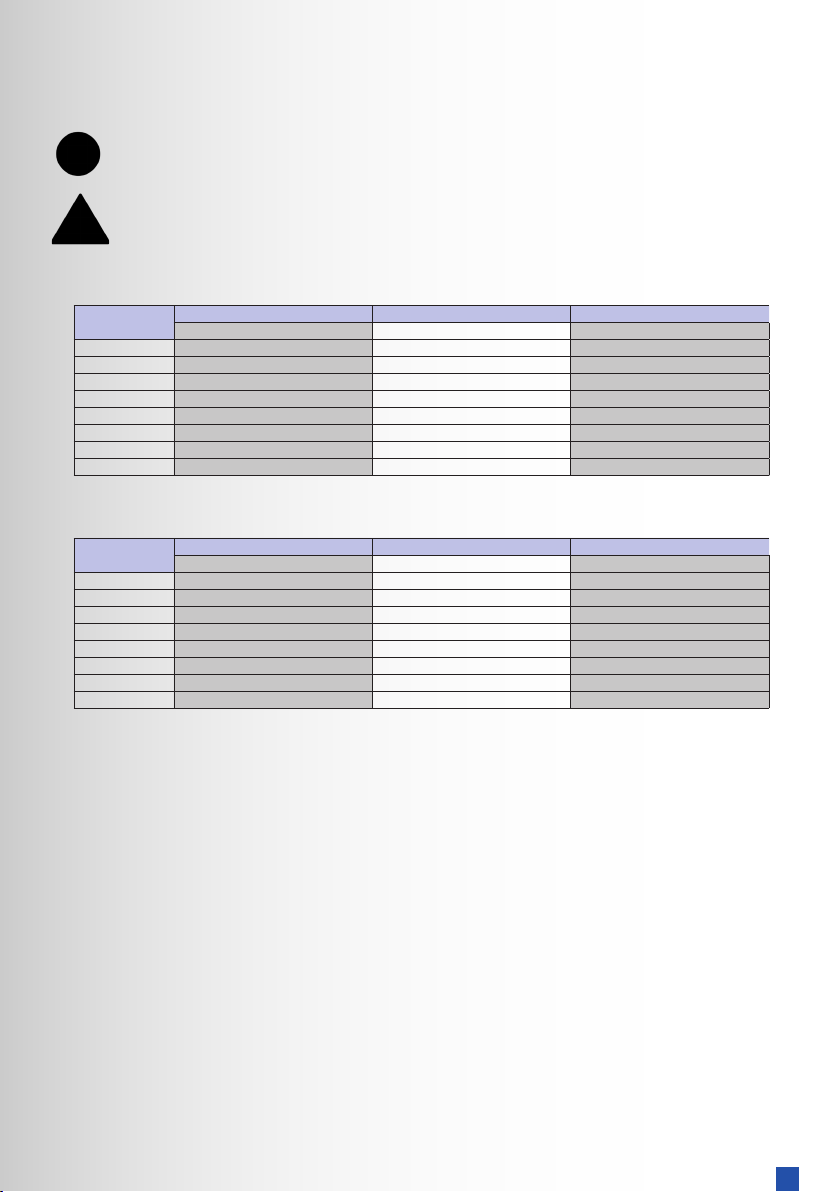
The correct orice diameter can be determined from the table below.
Oil Cooler
Series
Max. Sea water
ow I/min
1 bar 2 bar 3 bar 4 bar 5 bar 6 bar 7 bar 8 bar 9 bar 10 bar
EC 50 11 9.5 8.5 8 7.5 7.2 6.8 6.7 6.5 6.3
FC 80 14 12 11 10 9.5 9 8.7 8.4 8.2 8
FG 110 17 14 13 12 11 10 10 9.8 9.6 9.3
GL 200 23 19 17 16 15 14 14 13 13 13
GK 300 28 23 21 19 18 17 17 16 16 15
JK 400 32 27 24 22 21 20 20 19 18 18
PK 500 41 34 31 28 27 26 25 24 23 23
RK 900 48 40 36 34 32 30 29 28 27 26
2.6 Composite end cover water pipe installation
For marine versions supplied with composite end covers, it is recommended
that a bonded seal is used in conjunction with the tting and tightened to the
appropriate torque gure given below to ensure sucient sealing.
The following tables gives maximum ow rates for either single two or three pass
conguration, using either sea water or fresh water cooling.
Orice diameter in mm for max. sea water ow
Three Pass Bowman
Oil Coolers
Size Torque (Nm)
EC range (3/4” BSP) 10
FC range (1” BSP) 15
FG range (1 ¼” BSP) 20
GL range (1 ½” BSP) 25