Boyo VTL275HDL User manual

130528-1
VTL275HDL
VTL405HDL
VTL375HDL
VTL425HDL

• Installation and wiring of this product require specialist skill and experience.
To assure your safety, please request a specialist technician to install the unit.
• Make sure to ground the unit to a negative 12V DC power supply.
• When the product gets dirty, wipe dry with a silicon cloth or soft cloth. If it is seriously
stained, remove stain with a cloth moistened with a neutral cleaner and then wipe the
cleaner away. Do not use a hard cloth and/or a volatile substance such as lacquer
thinner or alcohol, scratches, deformation, degradation and/or damage may result.
• When a lens component gets dirty, wipe gently with a soft cloth moistened with water.
Do not rub with a dry cloth to prevent scratching the lens.
Caution:
1. Be careful that people are not exposed to the product as they generate heat over a
long period of time when LED is powered on.
Exposing a part of your hand close to the heat from the product may cause a burn.
2. Do not see the LED light directly,it may cause a blindness.
3. The colored guide lines on the display screen indicate vehicle width and approximate
distances to objects with reference to the vehicle body line.
4. There are some areas where the system will not show objects.
5. The distance between objects viewed on the display screen may differ from the
actual distance.
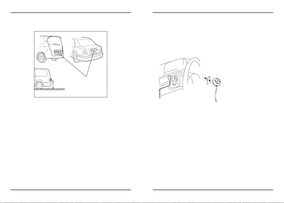
6. Install so that it does not obstruct the rear field of view.
7. Do not perform installation in rain or fog.
8. When humidity is high, dry the surface to which the unit is to be attached before
installing.
9. Do not apply water to the unit.
10. Do not expose the unit to rain.
11. Do not subject the camera to unnecessary force.
To prevent damage to the product, take the following precautions:
2 3
Before Use/ Installation Procedure
WARNING
Care and maintenance
CAUTION
• This product is a rear view camera for checking the view at the rear of a car.
• This product is designed to supplement the driver’s rear view, but the camera images
do not show all dangers and obstacles.
Be sure to look behind you when reversing to confi rm the view.
• This product features a wide-angle lens, so the near view is wide and the far view is
narrow, which may create a false sense of distance. Be sure to look behind you when
reversing to confi rm the view.
• Do not wash your car with an automatic car wash or high-pressure water as it may
result in water entering the camera or the camera falling off.
- If the rear view camera comes loose while you are driving it may cause an accident.
• Before fi nally installing the unit, connect the wiring temporarily, making sure it is all
connected up properly, and the unit and the system work.
• Do not mount this unit near the heater outlet, where it would be aff ected by heat, or
near the doors, where rainwater might splash onto it. (Never install in locations such as
the above because of the danger of malfunction due to high temperatures.)
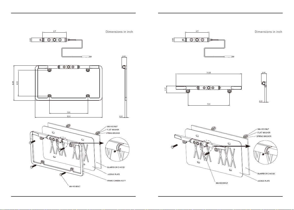
• Before drilling any mounting holes always check behind where you want to drill the
holes. Do not drill into the gas line, brake line, electrical wiring or other important parts.
NOTE

4 5
1. Package
Camera x1 manual x1 M6 Hex bolt x4
Spring washer x4 Plate washer x4 M6 Hex nut x4
1.5Ø L-Wrench x1 Adaptor cable x1
23ft Extension cable x1 Warranty card x1 Registration card x1
Table of contents
1. Package ------------------------------------------------------------ 5
2. Recommended Installation Position --------------------- 6~7
3.Wire Connections ------------------------------------------------- 8
4. Camera Setting ---------------------------------------------------9
5. How to use remote controller ----------------------------10~11
6. Dimension(inch)-------------------------------------------- 12~13
7. Specification------------------------------------------------------14
Rear View Camera
INSTRUCTION MANUAL
Please read this manual carefully before installation and operation of the product.
* Model
□ VTL275HDL
□ VTL375HDL
□ VTL405HDL
□ VTL425HDL
This limited warranty is given to the end-user or the retail purchaser (referred to this warranty as
“Original Purchaser”) that it will be free from defects in material and workmanship for a period of one year
from the date of the purchase of the new product (excluding accessory items such as power cords, cradle,
memory card, adaptor and cables).
A copy of the original proof of purchase and this warranty card with RMA number given by Vision
Tech America, Inc. is required to receive warranty service. In the unlikely event that the new product
should fail due to defect in material or workmanship, Vision Tech America, Inc. will repair or replace the
entire product, where each party will be responsible for one-way shipping.
This limited warranty does not cover any physical damage to this product, damage caused by improper
installation; improper use; misuse; neglect; repair of cracked, scratched, broken or modified cosmetics; or
parts that have been altered or removed; damages done by another device used with this product resulting
from use of non Vision - brand parts. This warranty is VOID if you purchased this product as used, floor
model sample, or refurbished; if the product has been altered or modified in any way (including but not
limited to attempted repair without authorization from Vision - Vision Tech America, Inc. and/or
alteration/removal of the serial number). This limited warranty does not cover the vehicle of any damages
or liabilities in which this product is installed or being installed. This product does not guarantee avoidance
of vehicle collision or accident.
If you think your product is eligible for warranty service, report to Vision Tech America, Inc. at
Model Number:
Serial Number:
Date of Purchase:
Purchased Store Name:
RMA Number:
Name:
Your address:
City:
State: Zip
Country:
3M double face paster x1
Remote controller x1

6 7
2. Recommended Installation Position
2-1 Examples of correct camera installation
2. Recommended Installation Position
2-2 Installing the Switch Unit
• Recommended Installation height : 3.25ft
1. Decide the camera installation position.
2. Clean the camera installation surface.
Using a commercially available cleaner, wipe dirt, moisture and oil away from the
surface on which the camera is to be attached.
3. Mount the camera on the license plate.
4. Fix the camera temporarily with screw.
5. Complete all of the required connections.
6. Display the camera video.
Some video monitors may switch automatically to the external video input function.
For details, read the instruction manual for your video monitor.
7. Change the shift lever to the R (Reverse) range to view the image of the rear of the
vehicle.
Before viewing the camera, apply the parking brake and chock the wheels so that the
vehicle will not move. Otherwise, an unexpected accident may result.
8. Adjust the camera angle so that the rear part of the vehicle or the rear bumper is
visible at the bottom of the monitor screen.
When adjusting the camera angle, be careful not to stretch the camera cord.
9. After adjusting the camera angle, tighten the retaining screws firmly.
Inspect the retaining screws at times. If they are loose, tighten them firmly.
10.Perform the operations in “Camera Setting”.
If an adjustment is not possible in the currently available range, change the camera
position before retrying.
11.Fix the camera firmly in position.
1. Clean the switch unit installation surface.
Using a commercially available cleaner, wipe dirt, moisture and oil away from the
surface on which the switch unit is to be attached.
2. Attach double-side adhesive tape on the bottom of the switch unit and then attach
it in an easy-to-operate position, for example near the dashboard on the driver seat
side.
Installation position

8 9
4-2. Preparation Before Camera Setting
The switch unit can be used to switch the image display mode, view/hide the guideline
display and adjust the camera.
1. Stop the vehicle.
In a parking space with white lines and tire stoppers, park the vehicle in the center of
the white line frame.
2. Advance the vehicle.
• Move the vehicle forward until the entire parking space can be viewed in the camera
image.
• Be sure to apply the parking brake and push the brake pedal so that the vehicle is
completely stationary. Perform the setting in a place that will not cause nuisance to
other people.
3. Wire Connections 4. Camera Setting
4-1. Switch Unit Operation
Video cord
1
2
POWER (Red + )
(Black - )

10 11
5. How to use remote controller 5. How to use remote controller
(LDC On) : Factory default.
STEP1.(Split view left / right) ==> Press SET STEP2.(LDC + RIGHT view) ==> Press SET
STEP3.(H-2Partition On) ==> Press SET
STEP4.(LDC+Top view On) ==> Press SET
STEP5.(Mirror On / Off): Factory Default or ==> Press LEFT
STEP6.(Parking line On / Off) ==> Press RIGHT
STEP8.(ACCE On / Off) ==> Press UP
STEP7.(LED On / Off) ==> Press DOWN

12 13
6. Dimension(inch) 6. Dimension(inch)

14 15
7. Specification
PLG
Day & Night Only COLOR
1.2mm Board Lens(192˚D)
Resolution More than 1000TV
S/N Ratio
Effective Pixels
720(H) x 480(V)
50dB(AGC OFF)
Min.Illumination
0.2Lux at F1.2(LED Off), 0Lux at F1.2(LED On)
V-REV(Mirror)
Split View left/right ON / OFF
H-2Partition
ON / OFF
LDC+TOP VIEW
ON / OFF
ON / OFF
ON / OFF
LED Control ON / OFF
Gain Control AUTO
DNR
Smear effect 0.005%
Gamma correction r=0.45
Power source
Model
AWB(2,000˚K ~ 10,500˚K)
VTL275HDL,VTL375HDL,VTL405HDL,VTL425HDL
1280(H) x 960(V)
20,000 hours
Storage Temperature/Humidity
ON
DC12V(Tolerence : 9VDC-16VDC
70mA(LED Off), 580mA(LED On)
Shutter Speed AUTO(1/30 ~ 1/30,000)
SENSOR
Image sensor 1/3 progressive scan CMOS
Total Pixel
Scanning system Progressive scan
ON / OFFACCE
LENS
MTBF
-20℃to +60℃/ Under 90% Non-condensing
LDC
Default ON
Operation Temperature/Humidity
-10
℃
to +50
℃
/ Under 90% Non-condensing
IRIS Control AUTO
White Balance
* Specifications are subject to change without prior notice for improvement.
MEMO

16 17
MEMO MEMO

18 19
MEMO MEMO

20 21
MEMO MEMO
Other manuals for VTL275HDL
1
This manual suits for next models
3
Table of contents
Other Boyo Dashcam manuals